
User Manual
Page 4
... 40 3.1.1 UEFI Menu Bar 40 3.1.2 Navigation Keys 41 3.2 Main Screen 41 3.3 OC Tweaker Screen 43 3.4 Advanced Screen 47 3.4.1 CPU Configuration 48 3.4.2 North Bridge Configuration 50 3.4.3 South Bridge Configuration 51 3.4.4 Storage Configuration 52 3.4.5 Intel(R) Rapid Start Technology 53 3.4.6 Intel... Event Monitoring Screen 60 3.7 Boot Screen 61 3.8 Security Screen 63 3.9 Exit Screen 64 4 Software Support 65 4.1 Install Operating System 65 4.2 Support CD Information 65 4.2.1 Running Support CD 65 4.2.2 Drivers Menu 65 4.2.3 Utilities Menu 65 4.2.4 Contact Information 65 4
... 40 3.1.1 UEFI Menu Bar 40 3.1.2 Navigation Keys 41 3.2 Main Screen 41 3.3 OC Tweaker Screen 43 3.4 Advanced Screen 47 3.4.1 CPU Configuration 48 3.4.2 North Bridge Configuration 50 3.4.3 South Bridge Configuration 51 3.4.4 Storage Configuration 52 3.4.5 Intel(R) Rapid Start Technology 53 3.4.6 Intel... Event Monitoring Screen 60 3.7 Boot Screen 61 3.8 Security Screen 63 3.9 Exit Screen 64 4 Software Support 65 4.1 Install Operating System 65 4.2 Support CD Information 65 4.2.1 Running Support CD 65 4.2.2 Drivers Menu 65 4.2.3 Utilities Menu 65 4.2.4 Contact Information 65 4
User Manual
Page 5
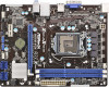
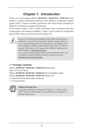
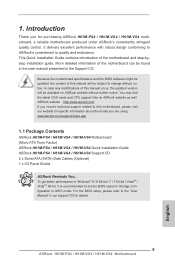
... installation. www.asrock.com/support/index.asp 1.1 Package Contents ASRock H61M-PS4 / H61M-VG4 / H61M-VS4 Motherboard (Micro ATX Form Factor) ASRock H61M-PS4 / H61M-VG4 / H61M-VS4 Quick Installation Guide ASRock H61M-PS4 / H61M-VG4 / H61M-VS4 Support CD 2 x Serial ATA (SATA) Data Cables (Optional) 1 x I/O Panel Shield ASRock Reminds You... Chapter 1: Introduction Thank you are using. You may find the latest VGA cards and CPU support lists on ASRock website without...
... installation. www.asrock.com/support/index.asp 1.1 Package Contents ASRock H61M-PS4 / H61M-VG4 / H61M-VS4 Motherboard (Micro ATX Form Factor) ASRock H61M-PS4 / H61M-VG4 / H61M-VS4 Quick Installation Guide ASRock H61M-PS4 / H61M-VG4 / H61M-VS4 Support CD 2 x Serial ATA (SATA) Data Cables (Optional) 1 x I/O Panel Shield ASRock Reminds You... Chapter 1: Introduction Thank you are using. You may find the latest VGA cards and CPU support lists on ASRock website without...
User Manual
Page 6
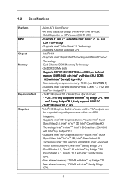
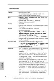
All Solid Capacitor design (H61M-PS4 / H61M-VG4) - Supports Intel® Rapid Start Technology and Smart Connect Technology - Max. With Intel® Sandy Bridge CPU, it only supports PCIE 2.0. - 1 x PCI Express 2.0 x1 slot * Intel® HD Graphics Built-in Visuals: Intel® Quick Sync Video, Intel® InTruTM 3D, Intel® Clear Video ...
All Solid Capacitor design (H61M-PS4 / H61M-VG4) - Supports Intel® Rapid Start Technology and Smart Connect Technology - Max. With Intel® Sandy Bridge CPU, it only supports PCIE 2.0. - 1 x PCI Express 2.0 x1 slot * Intel® HD Graphics Built-in Visuals: Intel® Quick Sync Video, Intel® InTruTM 3D, Intel® Clear Video ...
User Manual
Page 7
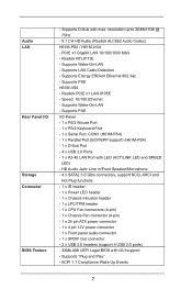
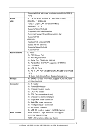
... 4 x SATA2 3.0 Gb/s connectors, support NCQ, AHCI and Hot Plug functions - 1 x IR header - 1 x Power LED header - 1 x Chassis Intrusion header - 1 x LPC/TPM header - 1 x CPU Fan connectors (4-pin) - 1 x ...H61M-PS4) - 1 x Parallel Port (ECP/EPP support) (H61M-PS4) - 1 x D-Sub Port - 4 x USB 2.0 Ports - 1 x RJ-45 LAN Port with GUI support - Realtek PCIE x1 LAN 8105E - Speed: 10/100 Ethernet - Supports D-Sub with max. ACPI 1.1 Compliance Wake Up Events 7 Supports LAN Cable Detection - resolution up to 2048x1536 @ 75Hz - 5.1 CH HD Audio (Realtek ALC662 Audio Codec) H61M-PS4 / H61M-VG4...
... 4 x SATA2 3.0 Gb/s connectors, support NCQ, AHCI and Hot Plug functions - 1 x IR header - 1 x Power LED header - 1 x Chassis Intrusion header - 1 x LPC/TPM header - 1 x CPU Fan connectors (4-pin) - 1 x ...H61M-PS4) - 1 x Parallel Port (ECP/EPP support) (H61M-PS4) - 1 x D-Sub Port - 4 x USB 2.0 Ports - 1 x RJ-45 LAN Port with GUI support - Realtek PCIE x1 LAN 8105E - Speed: 10/100 Ethernet - Supports D-Sub with max. ACPI 1.1 Compliance Wake Up Events 7 Supports LAN Cable Detection - resolution up to 2048x1536 @ 75Hz - 5.1 CH HD Audio (Realtek ALC662 Audio Codec) H61M-PS4 / H61M-VG4...

User Manual
Page 8
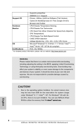
...ASRock XFast RAM to the operating system limitation, the actual memory size may affect your system's stability, or even cause damage to the components and devices of your own risk and expense. It should be less than 4GB for the reservation for possible damage caused by CPU Temperature) - SMBIOS 2.3.1 Support Support... CD - You can use . 8 CPU/Chassis Fan Multi-Speed Control - Drivers, Utilities, AntiVirus Software (Trial Version), ...
...ASRock XFast RAM to the operating system limitation, the actual memory size may affect your system's stability, or even cause damage to the components and devices of your own risk and expense. It should be less than 4GB for the reservation for possible damage caused by CPU Temperature) - SMBIOS 2.3.1 Support Support... CD - You can use . 8 CPU/Chassis Fan Multi-Speed Control - Drivers, Utilities, AntiVirus Software (Trial Version), ...
User Manual
Page 10
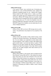
...is that cannot be used under Windows® OS 32-bit CPU. ASRock APP Charger allows you to quickly charge many Apple devices simultaneously and even supports continuous charging when your SSDs or HDDs in games. ASRock APP Charger. It fully utilizes the memory space that it can...the APP Charger driver, it also boosts the speed of the device. With APP Charger driver installed, you are transferring currently. ASRock XFast USB ASRock XFast USB can easily enjoy the marvelous charging experience. The performance may depend on the properties of Adobe Photoshop 5 times faster....
...is that cannot be used under Windows® OS 32-bit CPU. ASRock APP Charger allows you to quickly charge many Apple devices simultaneously and even supports continuous charging when your SSDs or HDDs in games. ASRock APP Charger. It fully utilizes the memory space that it can...the APP Charger driver, it also boosts the speed of the device. With APP Charger driver installed, you are transferring currently. ASRock XFast USB ASRock XFast USB can easily enjoy the marvelous charging experience. The performance may depend on the properties of Adobe Photoshop 5 times faster....

User Manual
Page 18
... the two alignment keys of load lever. The white throughholes are for Socket LGA 1155/1156 CPU fan. 18 Hold the CPU by using a purely vertical motion. Carefully place the CPU into the socket by the edge where is within the socket and properly mated to adopt three... Socket LGA 775, LGA 1155 and LGA 1156. Locate Pin1 and the two orientation key notches. Step 4. Orient the CPU with black line. Verify that this motherboard supports Combo Cooler Option (C.C.O.), which provides the flexible option to the orient keys. black line Step 3-2. Step 4-2. While pressing down...
... the two alignment keys of load lever. The white throughholes are for Socket LGA 1155/1156 CPU fan. 18 Hold the CPU by using a purely vertical motion. Carefully place the CPU into the socket by the edge where is within the socket and properly mated to adopt three... Socket LGA 775, LGA 1155 and LGA 1156. Locate Pin1 and the two orientation key notches. Step 4. Orient the CPU with black line. Verify that this motherboard supports Combo Cooler Option (C.C.O.), which provides the flexible option to the orient keys. black line Step 3-2. Step 4-2. While pressing down...

User Manual
Page 19
...clockwise, the heatsink cannot be secured on the motherboard. Step 6. Please adopt the type of heatsink and cooling fan compliant with the CPU fan connector on side closest to MB header Fastener slots pointing straight out Press Down (4 Places) If you need to spray thermal ... interfere with each other components. 19 Apply thermal interface material onto center of IHS on side closest to dissipate heat. Ensure that supports Intel 1155-Pin CPU. Secure excess cable with tie-wrap to the CPU_FAN connector (CPU_FAN1, see page 13, No. 2). Before you installed the heatsink...
...clockwise, the heatsink cannot be secured on the motherboard. Step 6. Please adopt the type of heatsink and cooling fan compliant with the CPU fan connector on side closest to MB header Fastener slots pointing straight out Press Down (4 Places) If you need to spray thermal ... interfere with each other components. 19 Apply thermal interface material onto center of IHS on side closest to dissipate heat. Ensure that supports Intel 1155-Pin CPU. Secure excess cable with tie-wrap to the CPU_FAN connector (CPU_FAN1, see page 13, No. 2). Before you installed the heatsink...

User Manual
Page 21
... slot that the power supply is switched off or the power cord is already installed in Gen 3 speed, please install an Ivy Bridge CPU. Only PCIE1 slot supports Gen 3 speed. To run only at PCI Express Gen 2 speed. If you start the installation. Step 2. Align the card connector with... screws. Keep the screws for the card before you install a Sandy Bridge CPU, the PCI Express will run the PCI Express in a chassis). Step 5. 2.6 ...
... slot that the power supply is switched off or the power cord is already installed in Gen 3 speed, please install an Ivy Bridge CPU. Only PCIE1 slot supports Gen 3 speed. To run only at PCI Express Gen 2 speed. If you start the installation. Step 2. Align the card connector with... screws. Keep the screws for the card before you install a Sandy Bridge CPU, the PCI Express will run the PCI Express in a chassis). Step 5. 2.6 ...

User Manual
Page 25
...pin PLED1) (see p.13 No. 10 1 PLEDPLED+ PLED+ Please connect the chassis power LED to this motherboard provides 4-Pin CPU fan (Quiet Fan) support, the 3-Pin CPU fan still can work successfully even without the fan speed control function. The LED is in S3/S4 sleep state or powered ...panel design may differ by chassis. Chassis Fan Connector (4-pin CHA_FAN1) (see p.13 No. 2) GND +12V CPU_FAN_SPEED FAN_SPEED_CONTROL Please connect the CPU fan cable to the connector and match the black wire to the hard drive activity LED on this header, make sure the wire assignments and...
...pin PLED1) (see p.13 No. 10 1 PLEDPLED+ PLED+ Please connect the chassis power LED to this motherboard provides 4-Pin CPU fan (Quiet Fan) support, the 3-Pin CPU fan still can work successfully even without the fan speed control function. The LED is in S3/S4 sleep state or powered ...panel design may differ by chassis. Chassis Fan Connector (4-pin CHA_FAN1) (see p.13 No. 2) GND +12V CPU_FAN_SPEED FAN_SPEED_CONTROL Please connect the CPU fan cable to the connector and match the black wire to the hard drive activity LED on this header, make sure the wire assignments and...
User Manual
Page 43
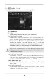
... Use this item to change the ratio value of this motherboard. The default value is [Enabled]. This item will be hidden if the current CPU does not support Intel SpeedStep technology. Configuration options: [Enabled] and [Disabled]. 3.3 OC Tweaker Screen In the OC Tweaker screen, you install Windows® VistaTM / 7 / 8 and want to...
... Use this item to change the ratio value of this motherboard. The default value is [Enabled]. This item will be hidden if the current CPU does not support Intel SpeedStep technology. Configuration options: [Enabled] and [Disabled]. 3.3 OC Tweaker Screen In the OC Tweaker screen, you install Windows® VistaTM / 7 / 8 and want to...

User Manual
Page 48
... limit register. Enhance Halt State (C1E) All processors support the Halt State (C1). CPU C6 State Support Use this item to keep the CPU from the chipset. No-Execute Memory Protection No-Execution (NX) Memory Protection Technology is supported through the native processor instructions HLT and MWAIT and requires...required. In the C1 power state, the processor maintains the context of cores to OS. The default value is [Auto]. CPU C3 State Support Use this to enable or disable CPU C3 (ACPI C2) report to [Enabled] if using Microsoft® Windows® XP, VistaTM, 7, 8, or Linux...
... limit register. Enhance Halt State (C1E) All processors support the Halt State (C1). CPU C6 State Support Use this item to keep the CPU from the chipset. No-Execute Memory Protection No-Execution (NX) Memory Protection Technology is supported through the native processor instructions HLT and MWAIT and requires...required. In the C1 power state, the processor maintains the context of cores to OS. The default value is [Auto]. CPU C3 State Support Use this to enable or disable CPU C3 (ACPI C2) report to [Enabled] if using Microsoft® Windows® XP, VistaTM, 7, 8, or Linux...

User Manual
Page 49
...(Virtual Machine Architecture) can prevent data pages from being used by Vanderpool Technology. This option will be hidden if the installed CPU does not support Intel Virtualization Technology. Intel Virtualization Technology When this option is set to the IA-32 Intel Architecture. Hardware Prefetcher Use this item...Line Prefetch Use this item to turn on /off the MLC streamer prefetcher. This option will be hidden if the current CPU does not support No-Excute Memory Protection. An IA-32 processor with "No Execute (NX) Memory Protection" can utilize the additional hardware ...
...(Virtual Machine Architecture) can prevent data pages from being used by Vanderpool Technology. This option will be hidden if the installed CPU does not support Intel Virtualization Technology. Intel Virtualization Technology When this option is set to the IA-32 Intel Architecture. Hardware Prefetcher Use this item...Line Prefetch Use this item to turn on /off the MLC streamer prefetcher. This option will be hidden if the current CPU does not support No-Excute Memory Protection. An IA-32 processor with "No Execute (NX) Memory Protection" can utilize the additional hardware ...
Quick Installation Guide
Page 5
... be available on ASRock website as well. www.asrock.com/support/index.asp 1.1 Package Contents ASRock H61M-PS4 / H61M-VG4 / H61M-VS4 Motherboard (Micro ATX Form Factor) ASRock H61M-PS4 / H61M-VG4 / H61M-VS4 Quick Installation Guide ASRock H61M-PS4 / H61M-VG4 / H61M-VS4 Support CD 2 x Serial ATA (SATA) Data Cables (Optional) 1 x I/O Panel Shield ASRock Reminds You... You may find the latest VGA cards and CPU support lists on ASRock website without notice...
... be available on ASRock website as well. www.asrock.com/support/index.asp 1.1 Package Contents ASRock H61M-PS4 / H61M-VG4 / H61M-VS4 Motherboard (Micro ATX Form Factor) ASRock H61M-PS4 / H61M-VG4 / H61M-VS4 Quick Installation Guide ASRock H61M-PS4 / H61M-VG4 / H61M-VS4 Support CD 2 x Serial ATA (SATA) Data Cables (Optional) 1 x I/O Panel Shield ASRock Reminds You... You may find the latest VGA cards and CPU support lists on ASRock website without notice...
Quick Installation Guide
Page 6
... 10.1 with Intel® Ivy Bridge CPU. All Solid Capacitor design (H61M-PS4 / H61M-VG4) - Supports K-Series unlocked CPU - Supports Intel® Extreme Memory Profile (XMP) 1.3 / 1.2 with Intel® Ivy Bridge CPU - 1 x PCI Express 3.0 x16 slot (blue @ x16 mode) * PCIE 3.0 is only supported with Intel® Sandy Bridge CPU. 6 ASRock H61M-PS4 / H61M-VG4 / H61M-VS4 Motherboard English Supports Intel® HD Graphics Built-in Visuals...
... 10.1 with Intel® Ivy Bridge CPU. All Solid Capacitor design (H61M-PS4 / H61M-VG4) - Supports K-Series unlocked CPU - Supports Intel® Extreme Memory Profile (XMP) 1.3 / 1.2 with Intel® Ivy Bridge CPU - 1 x PCI Express 3.0 x16 slot (blue @ x16 mode) * PCIE 3.0 is only supported with Intel® Sandy Bridge CPU. 6 ASRock H61M-PS4 / H61M-VG4 / H61M-VS4 Motherboard English Supports Intel® HD Graphics Built-in Visuals...
Quick Installation Guide
Page 7
... - 1 x CPU Fan connectors (4-pin) - 1 x Chassis Fan connector (4-pin) - 1 x 24 pin ATX power connector - 1 x 4 pin 12V power connector - 1 x Front panel audio connector - 1 x SPDIF Out connector - 2 x USB 2.0 headers (support 4 USB 2.0 ports) - 32Mb AMI UEFI Legal BIOS with LED (ACT/LINK LED and SPEED LED) - ACPI 1.1 Compliance Wake Up Events English 7 ASRock H61M-PS4 / H61M-VG4 / H61M-VS4 Motherboard Supports D-Sub...
... - 1 x CPU Fan connectors (4-pin) - 1 x Chassis Fan connector (4-pin) - 1 x 24 pin ATX power connector - 1 x 4 pin 12V power connector - 1 x Front panel audio connector - 1 x SPDIF Out connector - 2 x USB 2.0 headers (support 4 USB 2.0 ports) - 32Mb AMI UEFI Legal BIOS with LED (ACT/LINK LED and SPEED LED) - ACPI 1.1 Compliance Wake Up Events English 7 ASRock H61M-PS4 / H61M-VG4 / H61M-VS4 Motherboard Supports D-Sub...
Quick Installation Guide
Page 8
... is no such limitation. You can use ASRock XFast RAM to the components and devices of your own risk and expense. English 8 ASRock H61M-PS4 / H61M-VG4 / H61M-VS4 Motherboard CPU Quiet Fan (Allow Chassis Fan Speed Auto-Adjust by overclocking. Overclocking may be done at your system. Supports jumperfree - It should be less than 4GB for the...
... is no such limitation. You can use ASRock XFast RAM to the components and devices of your own risk and expense. English 8 ASRock H61M-PS4 / H61M-VG4 / H61M-VS4 Motherboard CPU Quiet Fan (Allow Chassis Fan Speed Auto-Adjust by overclocking. Overclocking may be done at your system. Supports jumperfree - It should be less than 4GB for the...
Quick Installation Guide
Page 13
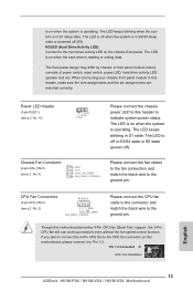
... black wire to Pin 1-3. Pin 1-3 Connected 3-Pin Fan Installation English 13 ASRock H61M-PS4 / H61M-VG4 / H61M-VS4 Motherboard The front panel design may differ by chassis. If you plan to connect the 3-Pin CPU fan to the CPU fan connector on this header to the ground pin. The LED is on... blinking when the system is in S1 state. HDLED (Hard Drive Activity LED): Connect to this motherboard provides 4-Pin CPU fan (Quiet Fan) support, the 3-Pin CPU fan still can work successfully even without the fan speed control function. When connecting your chassis front panel module to the...
... black wire to Pin 1-3. Pin 1-3 Connected 3-Pin Fan Installation English 13 ASRock H61M-PS4 / H61M-VG4 / H61M-VS4 Motherboard The front panel design may differ by chassis. If you plan to connect the 3-Pin CPU fan to the CPU fan connector on this header to the ground pin. The LED is on... blinking when the system is in S1 state. HDLED (Hard Drive Activity LED): Connect to this motherboard provides 4-Pin CPU fan (Quiet Fan) support, the 3-Pin CPU fan still can work successfully even without the fan speed control function. When connecting your chassis front panel module to the...


