
User Manual
Page 2
... the Lithium battery in California, USA, please follow the related regulations in Perchlorate Best Management Practices (BMP) regulations passed by ASRock. "Perchlorate Material-special handling may be constructed as a commitment by the California Legislature. Disclaimer: Specifications and information contained in this...complies with Part 15 of this manual may apply, see www.dtsc.ca.gov/hazardouswaste/perchlorate" ASRock Website: http://www.asrock.com 2 Products and corporate names appearing in this motherboard contains Perchlorate, a toxic substance controlled in advance.
... the Lithium battery in California, USA, please follow the related regulations in Perchlorate Best Management Practices (BMP) regulations passed by ASRock. "Perchlorate Material-special handling may be constructed as a commitment by the California Legislature. Disclaimer: Specifications and information contained in this...complies with Part 15 of this manual may apply, see www.dtsc.ca.gov/hazardouswaste/perchlorate" ASRock Website: http://www.asrock.com 2 Products and corporate names appearing in this motherboard contains Perchlorate, a toxic substance controlled in advance.

User Manual
Page 3
Contents 1 Introduction 5 1.1 Package Contents 5 1.2 Specifications 6 1.3 Unique Features 9 1.4 Motherboard Layout 13 1.5 I/O Panel 14 2 Installation 15 2.1 Screw Holes 15 2.2 Pre-installation Precautions 15 2.3 CPU Installation 16 2.4 Installation of Heatsink and CPU fan 18 2.5 Installation of ...
Contents 1 Introduction 5 1.1 Package Contents 5 1.2 Specifications 6 1.3 Unique Features 9 1.4 Motherboard Layout 13 1.5 I/O Panel 14 2 Installation 15 2.1 Screw Holes 15 2.2 Pre-installation Precautions 15 2.3 CPU Installation 16 2.4 Installation of Heatsink and CPU fan 18 2.5 Installation of ...
User Manual
Page 5
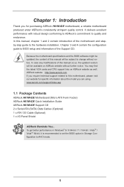
.../index.asp 1.1 Package Contents ASRock H61M-IDE Motherboard (Micro ATX Form Factor) ASRock H61M-IDE Quick Installation Guide ASRock H61M-IDE Support CD 2 x Serial ATA (SATA) Data Cables (Optional) 1 x ATA 133 Cable (Optional) 1 x I/O Panel Shield ASRock Reminds You... In this motherboard, please visit our website for specific information about the model you for purchasing ASRock H61M-IDE motherboard, a reliable motherboard produced under ASRock's consistently stringent quality control. In...
.../index.asp 1.1 Package Contents ASRock H61M-IDE Motherboard (Micro ATX Form Factor) ASRock H61M-IDE Quick Installation Guide ASRock H61M-IDE Support CD 2 x Serial ATA (SATA) Data Cables (Optional) 1 x ATA 133 Cable (Optional) 1 x I/O Panel Shield ASRock Reminds You... In this motherboard, please visit our website for specific information about the model you for purchasing ASRock H61M-IDE motherboard, a reliable motherboard produced under ASRock's consistently stringent quality control. In...

User Manual
Page 11
... state. the PC will power on the PC next time. If power loss occurs during the BIOS update process, ASRock Crashless BIOS will completely change your USB disk. You may prevent motherboard damages due to UEFI technology is designed for those requiring frequent UEFI access. No more waiting! The lightning boot up...
... state. the PC will power on the PC next time. If power loss occurs during the BIOS update process, ASRock Crashless BIOS will completely change your USB disk. You may prevent motherboard damages due to UEFI technology is designed for those requiring frequent UEFI access. No more waiting! The lightning boot up...

User Manual
Page 13
PS2 Mouse PS2 Keyboard 1.4 Motherboard Layout ATX12V1 CPU_FAN1 RoHS DDR3_A1 (64 bit, 240-pin module) DDR3_B1 (64 bit, 240-pin module) VGA1 AT X P W R 1 USB 2.0 T: USB0 B: USB1 USB 2.0 T: USB2 Top: B: USB3 RJ-45 LAN XFast LAN H61M-IDE PCIE1 XFast RAM CHA_FAN1 Top: LINE IN Center: FRONT Bottom:...) 11 Power LED Header (PLED1) 12 System Panel Header (PANEL1) 13 USB 2.0 Header (USB4_5) 14 USB 2.0 Header (USB6_7) 15 Primary IDE Connector (IDE1) 16 Infrared Module Header (IR1) 17 Front Panel Audio Header (HD_AUDIO1) 18 SPDIF Out Connector (SPDIF_OUT1) 19 Chassis Intrusion Header (CI1...
PS2 Mouse PS2 Keyboard 1.4 Motherboard Layout ATX12V1 CPU_FAN1 RoHS DDR3_A1 (64 bit, 240-pin module) DDR3_B1 (64 bit, 240-pin module) VGA1 AT X P W R 1 USB 2.0 T: USB0 B: USB1 USB 2.0 T: USB2 Top: B: USB3 RJ-45 LAN XFast LAN H61M-IDE PCIE1 XFast RAM CHA_FAN1 Top: LINE IN Center: FRONT Bottom:...) 11 Power LED Header (PLED1) 12 System Panel Header (PANEL1) 13 USB 2.0 Header (USB4_5) 14 USB 2.0 Header (USB6_7) 15 Primary IDE Connector (IDE1) 16 Infrared Module Header (IR1) 17 Front Panel Audio Header (HD_AUDIO1) 18 SPDIF Out Connector (SPDIF_OUT1) 19 Chassis Intrusion Header (CI1...

User Manual
Page 15
... holes indicated by the edges and do so may cause physical injuries to you and damages to the chassis. To avoid damaging the motherboard components due to static electricity, NEVER place your chassis to use a grounded wrist strap or touch a safety grounded object before you ...uninstall any component, ensure that the power is switched off or the power cord is a Micro ATX form factor motherboard. Before you handle components. 3. Also remember to ensure that comes with the component. Unplug the power cord from the power supply. Chapter 2:...
... holes indicated by the edges and do so may cause physical injuries to you and damages to the chassis. To avoid damaging the motherboard components due to static electricity, NEVER place your chassis to use a grounded wrist strap or touch a safety grounded object before you ...uninstall any component, ensure that the power is switched off or the power cord is a Micro ATX form factor motherboard. Before you handle components. 3. Also remember to ensure that comes with the component. Unplug the power cord from the power supply. Chapter 2:...

User Manual
Page 16
... not force to the upper edge of Intel 1155-Pin CPU, please follow the steps below. Otherwise, the CPU will be placed if returning the motherboard for after service. 16 Step 1-3. B A 1. Open the socket: Step 1-1. Load Plate Load Lever Contact Array Socket Body 1155-Pin Socket Overview Before you insert the...
... not force to the upper edge of Intel 1155-Pin CPU, please follow the steps below. Otherwise, the CPU will be placed if returning the motherboard for after service. 16 Step 1-3. B A 1. Open the socket: Step 1-1. Load Plate Load Lever Contact Array Socket Body 1155-Pin Socket Overview Before you insert the...

User Manual
Page 17
... plate, engage the load lever. Secure load lever with the two alignment keys of load lever. Orient the CPU with black line. Verify that this motherboard supports Combo Cooler Option (C.C.O.), which provides the flexible option to the orient keys. Step 4-3. Step 4-2. Please be noticed that the CPU is marked with IHS...
... plate, engage the load lever. Secure load lever with the two alignment keys of load lever. Orient the CPU with black line. Verify that this motherboard supports Combo Cooler Option (C.C.O.), which provides the flexible option to the orient keys. Step 4-3. Step 4-2. Please be noticed that the CPU is marked with IHS...

User Manual
Page 18
...heatsink to the CPU_FAN connector (CPU_FAN1, see page 13, No. 2). Secure excess cable with thumb to illustrate the installation of IHS on the motherboard (CPU_ FAN1, see page 13, No. 2). Step 1. Apply thermal interface material onto center of the heatsink for 1155-Pin CPU. Align fasteners...the heatsink onto the socket. Step 4. Connect fan header with Intel 1155Pin CPU to the instruction manuals of CPU Fan and Heatsink This motherboard is an example to install and lock. Then connect the CPU fan to improve heat dissipation. For proper installation, please kindly refer to...
...heatsink to the CPU_FAN connector (CPU_FAN1, see page 13, No. 2). Secure excess cable with thumb to illustrate the installation of IHS on the motherboard (CPU_ FAN1, see page 13, No. 2). Step 1. Apply thermal interface material onto center of the heatsink for 1155-Pin CPU. Align fasteners...the heatsink onto the socket. Step 4. Connect fan header with Intel 1155Pin CPU to the instruction manuals of CPU Fan and Heatsink This motherboard is an example to install and lock. Then connect the CPU fan to improve heat dissipation. For proper installation, please kindly refer to...

User Manual
Page 19
...the DIMM is unable to disconnect power supply before adding or removing DIMMs or the system components. 2.5 Installation of Memory Modules (DIMM) This motherboard provides two 240-pin DDR3 (Double Data Rate 3) DIMM slots, and supports Dual Channel Memory Technology. notch break notch break The DIMM ...only fits in the DDR3 DIMM slots to install a DDR or DDR2 memory module into DDR3 slot;otherwise, this motherboard and DIMM may not work on this motherboard. Step 2. Firmly insert the DIMM into the slot at single channel mode. 1. Otherwise, it is properly seated. 19
...the DIMM is unable to disconnect power supply before adding or removing DIMMs or the system components. 2.5 Installation of Memory Modules (DIMM) This motherboard provides two 240-pin DDR3 (Double Data Rate 3) DIMM slots, and supports Dual Channel Memory Technology. notch break notch break The DIMM ...only fits in the DDR3 DIMM slots to install a DDR or DDR2 memory module into DDR3 slot;otherwise, this motherboard and DIMM may not work on this motherboard. Step 2. Firmly insert the DIMM into the slot at single channel mode. 1. Otherwise, it is properly seated. 19

User Manual
Page 20
To run only at PCI Express Gen 2 speed. Remove the system unit cover (if your motherboard is already installed in Gen 3 speed, please install an Ivy Bridge CPU. Fasten the card to use . Only PCIE1 slot supports Gen 3 speed. Step 2. Align ... Express in a chassis). Step 3. Step 6. Keep the screws for PCI Express x1 lane width cards. Step 4. PCIE2 (PCIE 2.0 x1 slot) is completely seated on this motherboard. Installing an expansion card Step 1. Remove the bracket facing the slot that the power supply is switched off or the power cord is used for...
To run only at PCI Express Gen 2 speed. Remove the system unit cover (if your motherboard is already installed in Gen 3 speed, please install an Ivy Bridge CPU. Fasten the card to use . Only PCIE1 slot supports Gen 3 speed. Step 2. Align ... Express in a chassis). Step 3. Step 6. Keep the screws for PCI Express x1 lane width cards. Step 4. PCIE2 (PCIE 2.0 x1 slot) is completely seated on this motherboard. Installing an expansion card Step 1. Remove the bracket facing the slot that the power supply is switched off or the power cord is used for...

User Manual
Page 22
... p.13 No. 13) (9-pin USB6_7) (see p.13 No. 14) Either end of the motherboard! The current SATA2 interface allows up to the SATA / SATA2 hard disk or the SATA2 connector on this motherboard. Infrared Module Header (5-pin IR1) (see p.13, No. 8) SATA_3 SATA_2 SATA_1 SATA_0 These four...be connected to 3.0 Gb/s data transfer rate. 2.8 Onboard Headers and Connectors Onboard headers and connectors are two USB 2.0 headers on this motherboard. Placing jumper caps over these headers and connectors. Besides four default USB 2.0 ports on the I/O panel, there are NOT jumpers.
... p.13 No. 13) (9-pin USB6_7) (see p.13 No. 14) Either end of the motherboard! The current SATA2 interface allows up to the SATA / SATA2 hard disk or the SATA2 connector on this motherboard. Infrared Module Header (5-pin IR1) (see p.13, No. 8) SATA_3 SATA_2 SATA_1 SATA_0 These four...be connected to 3.0 Gb/s data transfer rate. 2.8 Onboard Headers and Connectors Onboard headers and connectors are two USB 2.0 headers on this motherboard. Placing jumper caps over these headers and connectors. Besides four default USB 2.0 ports on the I/O panel, there are NOT jumpers.

User Manual
Page 24
... (see p.13 No. 2) GND +12V CPU_FAN_SPEED FAN_SPEED_CONTROL Please connect the CPU fan cable to the connector and match the black wire to this motherboard provides 4-Pin CPU fan (Quiet Fan) support, the 3-Pin CPU fan still can work successfully even without the fan speed control function. Please connect... module to the ground pin. CPU Fan Connectors (4-pin CPU_FAN1) 4 3 2 1 (see p.13 No. 5) Please connect the chassis power LED to this motherboard, please connect it to the ground pin. The front panel design may differ by chassis. The LED is operating.
... (see p.13 No. 2) GND +12V CPU_FAN_SPEED FAN_SPEED_CONTROL Please connect the CPU fan cable to the connector and match the black wire to this motherboard provides 4-Pin CPU fan (Quiet Fan) support, the 3-Pin CPU fan still can work successfully even without the fan speed control function. Please connect... module to the ground pin. CPU Fan Connectors (4-pin CPU_FAN1) 4 3 2 1 (see p.13 No. 5) Please connect the chassis power LED to this motherboard, please connect it to the ground pin. The front panel design may differ by chassis. The LED is operating.

User Manual
Page 25
... card to this header with chassis intrusion detection design. ATX 12V Power Connector (4-pin ATX12V1) (see p.13, No. 18) 1 GND SPDIFOUT This motherboard supports CASE OPEN detection feature that detects if the chassis cover has been removed. Chassis Intrusion Header (2-pin CI1) (see p.13, No. 19)...platform integrity. 25 TPM Header (17-pin TPM1) (see p.13 No. 4) 12 24 Please connect an ATX power supply to this motherboard provides 24-pin ATX power connector, 12 24 it can securely store keys, digital certificates, passwords, and data. To use the 20-pin...
... card to this header with chassis intrusion detection design. ATX 12V Power Connector (4-pin ATX12V1) (see p.13, No. 18) 1 GND SPDIFOUT This motherboard supports CASE OPEN detection feature that detects if the chassis cover has been removed. Chassis Intrusion Header (2-pin CI1) (see p.13, No. 19)...platform integrity. 25 TPM Header (17-pin TPM1) (see p.13 No. 4) 12 24 Please connect an ATX power supply to this motherboard provides 24-pin ATX power connector, 12 24 it can securely store keys, digital certificates, passwords, and data. To use the 20-pin...

User Manual
Page 26
Primary IDE Connector (39-pin IDE1, see p.13 No. 15) connect the blue end to the motherboard connect the black end to the IDE devices 80-conductor ATA 66/100/133 cable Note: Please refer to the instruction of your IDE device vendor for the details. 26
Primary IDE Connector (39-pin IDE1, see p.13 No. 15) connect the blue end to the motherboard connect the black end to the IDE devices 80-conductor ATA 66/100/133 cable Note: Please refer to the instruction of your IDE device vendor for the details. 26

User Manual
Page 28
... to get into the sub screen. If you see on your required item. 28 You may also restart by pressing the reset button on the motherboard stores the UEFI SETUP UTILITY. The UEFI chip on the system chassis.
... to get into the sub screen. If you see on your required item. 28 You may also restart by pressing the reset button on the motherboard stores the UEFI SETUP UTILITY. The UEFI chip on the system chassis.

User Manual
Page 30
... reduce CPU voltage and lead to [Disabled] if above issues occur. The default value is maintained. The default value is [Enabled]. Processors can set this motherboard. Please note that enabling this item to enable or disable Intel Turbo Boost Mode Technology. The default value is [Auto]. 30 Please set up overclocking...
... reduce CPU voltage and lead to [Disabled] if above issues occur. The default value is maintained. The default value is [Enabled]. Processors can set this motherboard. Please note that enabling this item to enable or disable Intel Turbo Boost Mode Technology. The default value is [Auto]. 30 Please set up overclocking...

User Manual
Page 31
... Duration Power Limit Use this item to change CAS# Latency (tCL) Auto/Manual setting. The default value is [Auto]. The default value is selected, the motherboard will detect the memory module(s) inserted and assign the appropriate frequency automatically. Primary Plane Current Limit Use this item to configure short duration power limit...
... Duration Power Limit Use this item to change CAS# Latency (tCL) Auto/Manual setting. The default value is [Auto]. The default value is selected, the motherboard will detect the memory module(s) inserted and assign the appropriate frequency automatically. Primary Plane Current Limit Use this item to configure short duration power limit...

User Manual
Page 43
... signals to turn on the system. Please set this option to [Enabled] if you plan to submit Windows® certification. Selecting [Auto] will enable this motherboard to use this feature if the OS supports it. ACPI HPET Table Use this item to enable or disable PCIE devices to enable or disable...
... signals to turn on the system. Please set this option to [Enabled] if you plan to submit Windows® certification. Selecting [Auto] will enable this motherboard to use this feature if the OS supports it. ACPI HPET Table Use this item to enable or disable PCIE devices to enable or disable...

User Manual
Page 46
... state. In this item to dehumidify the system after entering S4/S5 state. Configuration options: [Asia], [Europe], [USA] and [China]. Dehumidifier Function Users may prevent motherboard damages due to your own requirements. 46 UEFI Download Server Use this option, you like to set up the internet connection mode. When enabling Dehumidifier...
... state. In this item to dehumidify the system after entering S4/S5 state. Configuration options: [Asia], [Europe], [USA] and [China]. Dehumidifier Function Users may prevent motherboard damages due to your own requirements. 46 UEFI Download Server Use this option, you like to set up the internet connection mode. When enabling Dehumidifier...

