
User Manual
Page 3
... and Connectors 22 2.9 Driver Installation Guide 27 3 UEFI SETUP UTILITY 28 3.1 Introduction 28 3.1.1 UEFI Menu Bar 28 3.1.2 Navigation Keys 29 3.2 Main Screen 29 3.3 OC Tweaker Screen 30 3.4 Advanced Screen 34 3.4.1 CPU Configuration 35 3.4.2 North Bridge Configuration 37 3.4.3 South Bridge Configuration 38 3.4.4 Storage Configuration 39 3.4.5 Intel(R) Rapid Start Technology 40 3.4.6 Intel(R) Smart Connect Technology 41 3.4.7 Super IO Configuration 42 3.4.8 ACPI Configuration 43 3.4.9 USB Configuration 44 3.5 Tool 45 3.6 Hardware Health Event Monitoring Screen 47 3.7 Boot...
... and Connectors 22 2.9 Driver Installation Guide 27 3 UEFI SETUP UTILITY 28 3.1 Introduction 28 3.1.1 UEFI Menu Bar 28 3.1.2 Navigation Keys 29 3.2 Main Screen 29 3.3 OC Tweaker Screen 30 3.4 Advanced Screen 34 3.4.1 CPU Configuration 35 3.4.2 North Bridge Configuration 37 3.4.3 South Bridge Configuration 38 3.4.4 Storage Configuration 39 3.4.5 Intel(R) Rapid Start Technology 40 3.4.6 Intel(R) Smart Connect Technology 41 3.4.7 Super IO Configuration 42 3.4.8 ACPI Configuration 43 3.4.9 USB Configuration 44 3.5 Tool 45 3.6 Hardware Health Event Monitoring Screen 47 3.7 Boot...
User Manual
Page 5
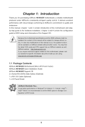
... updated version will be available on ASRock website as well. Because the motherboard specifications and the BIOS software might be updated, the content of the Support CD. In case any modifications of the motherboard and stepby-step guide to AHCI mode. 5 ASRock website http://www.asrock.com If you are using. www.asrock.com/support/index.asp 1.1 Package Contents ASRock H61M-IDE Motherboard (Micro ATX Form Factor) ASRock H61M-IDE Quick Installation Guide ASRock H61M-IDE Support CD 2 x Serial ATA (SATA) Data Cables (Optional) 1 x ATA 133 Cable (Optional) 1 x I/O Panel Shield ASRock...
... updated version will be available on ASRock website as well. Because the motherboard specifications and the BIOS software might be updated, the content of the Support CD. In case any modifications of the motherboard and stepby-step guide to AHCI mode. 5 ASRock website http://www.asrock.com If you are using. www.asrock.com/support/index.asp 1.1 Package Contents ASRock H61M-IDE Motherboard (Micro ATX Form Factor) ASRock H61M-IDE Quick Installation Guide ASRock H61M-IDE Support CD 2 x Serial ATA (SATA) Data Cables (Optional) 1 x ATA 133 Cable (Optional) 1 x I/O Panel Shield ASRock...

User Manual
Page 6
... Start Technology and Smart Connect Technology - capacity of system memory: 16GB (see CAUTION 1) - Pixel Shader 4.1, DirectX 10.1 with Intel® Ivy Bridge CPU. Max. shared memory 1760MB with Intel® Sandy Bridge CPU. - Micro ATX Form Factor - Supports Intel® Extreme Memory Profile (XMP) 1.3 / 1.2 with Intel® Ivy Bridge CPU - 1 x PCI Express 3.0 x16 Slot (Blue @ x16 mode) * PCIE 3.0 is only supported with Intel® Sandy Bridge CPU - Supports Intel® HD Graphics Built...
... Start Technology and Smart Connect Technology - capacity of system memory: 16GB (see CAUTION 1) - Pixel Shader 4.1, DirectX 10.1 with Intel® Ivy Bridge CPU. Max. shared memory 1760MB with Intel® Sandy Bridge CPU. - Micro ATX Form Factor - Supports Intel® Extreme Memory Profile (XMP) 1.3 / 1.2 with Intel® Ivy Bridge CPU - 1 x PCI Express 3.0 x16 Slot (Blue @ x16 mode) * PCIE 3.0 is only supported with Intel® Sandy Bridge CPU - Supports Intel® HD Graphics Built...

User Manual
Page 7
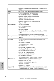
...Supports Wake-On-LAN - Supports Energy Efficient Ethernet 802.3az - HD Audio Jacks: Line in/Front Speaker/Microphone - 4 x SATA2 3.0 Gb/s Connectors, support NCQ, AHCI and Hot Plug - 1 x ATA133 IDE Connector (Supports 2 x IDE devices) - 1 x IR Header - 1 x Power LED Header - 1 x Chassis Intrusion Header - 1 x TPM Header - 1 x CPU Fan Connectors (4-pin) - 1 x Chassis Fan Connector (4-pin) - 1 x 24 pin ATX Power Connector - 1 x 4 pin 12V Power Connector - 1 x Front Panel Audio Connector - 1 x SPDIF Out Connector - 2 x USB 2.0 Headers (Support 4 USB 2.0 ports) - 32Mb AMI UEFI Legal BIOS with LED...
...Supports Wake-On-LAN - Supports Energy Efficient Ethernet 802.3az - HD Audio Jacks: Line in/Front Speaker/Microphone - 4 x SATA2 3.0 Gb/s Connectors, support NCQ, AHCI and Hot Plug - 1 x ATA133 IDE Connector (Supports 2 x IDE devices) - 1 x IR Header - 1 x Power LED Header - 1 x Chassis Intrusion Header - 1 x TPM Header - 1 x CPU Fan Connectors (4-pin) - 1 x Chassis Fan Connector (4-pin) - 1 x 24 pin ATX Power Connector - 1 x 4 pin 12V Power Connector - 1 x Front Panel Audio Connector - 1 x SPDIF Out Connector - 2 x USB 2.0 Headers (Support 4 USB 2.0 ports) - 32Mb AMI UEFI Legal BIOS with LED...

User Manual
Page 9
... save the new BIOS file to your USB flash drive, floppy disk or hard drive, then you can press the key during the shutdown and startup process, Instant Boot allows you can update your Windows® desktop in a few clicks without entering operating systems first like MSDOS or Windows®. It leverages the S3 and S4 ACPI features which includes Hardware Monitor, Fan Control and XFast RAM. ASRock Instant Flash ASRock Instant Flash is an...
... save the new BIOS file to your USB flash drive, floppy disk or hard drive, then you can press the key during the shutdown and startup process, Instant Boot allows you can update your Windows® desktop in a few clicks without entering operating systems first like MSDOS or Windows®. It leverages the S3 and S4 ACPI features which includes Hardware Monitor, Fan Control and XFast RAM. ASRock Instant Flash ASRock Instant Flash is an...

User Manual
Page 13
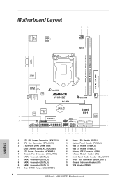
... USB 2.0 T: USB2 Top: B: USB3 RJ-45 LAN XFast LAN H61M-IDE PCIE1 XFast RAM CHA_FAN1 Top: LINE IN Center: FRONT Bottom: MIC IN AUDIO CODEC Super I/O CMOS BATTERY HD_AUDIO1 CI1 1 1 1 SPDIF_OUT1 IR1 TPM1 1 1 IDE1 PCIE2 USB4_5 1 USB6_7 1 CLRCMOS1 1 PLED1 1 PLED PWRBTN 1 HDLED RESET PANEL1 Intel H61 SATA_3 SATA_1 32Mb BIOS SATA_2 SATA_0 1 ATX 12V Power Connector (ATX12V1) 2 CPU Fan Connector (CPU_FAN1) 3 2 x 240-pin DDR3 DIMM Slots (Dual Channel: DDR3_A1, DDR3_B1) 4 ATX Power Connector (ATXPWR1) 5 Chassis Fan Connector...
... USB 2.0 T: USB2 Top: B: USB3 RJ-45 LAN XFast LAN H61M-IDE PCIE1 XFast RAM CHA_FAN1 Top: LINE IN Center: FRONT Bottom: MIC IN AUDIO CODEC Super I/O CMOS BATTERY HD_AUDIO1 CI1 1 1 1 SPDIF_OUT1 IR1 TPM1 1 1 IDE1 PCIE2 USB4_5 1 USB6_7 1 CLRCMOS1 1 PLED1 1 PLED PWRBTN 1 HDLED RESET PANEL1 Intel H61 SATA_3 SATA_1 32Mb BIOS SATA_2 SATA_0 1 ATX 12V Power Connector (ATX12V1) 2 CPU Fan Connector (CPU_FAN1) 3 2 x 240-pin DDR3 DIMM Slots (Dual Channel: DDR3_A1, DDR3_B1) 4 ATX Power Connector (ATXPWR1) 5 Chassis Fan Connector...

User Manual
Page 25
... can still work if you adopt a traditional 20-pin ATX power supply. This feature requires a chassis with a cable. Please connect the SPDIF_OUT connector of a HDMI VGA card to this header with chassis intrusion detection design. Chassis Intrusion Header (2-pin CI1) (see p.13, No. 19) 1 GND Signal SPDIF Out Connector (2-pin SPDIF_OUT1) (see p.13, No. 18) 1 GND SPDIFOUT This motherboard supports CASE OPEN detection feature that detects if the chassis cover has been removed. ATX 12V Power Connector (4-pin ATX12V1...
... can still work if you adopt a traditional 20-pin ATX power supply. This feature requires a chassis with a cable. Please connect the SPDIF_OUT connector of a HDMI VGA card to this header with chassis intrusion detection design. Chassis Intrusion Header (2-pin CI1) (see p.13, No. 19) 1 GND Signal SPDIF Out Connector (2-pin SPDIF_OUT1) (see p.13, No. 18) 1 GND SPDIFOUT This motherboard supports CASE OPEN detection feature that detects if the chassis cover has been removed. ATX 12V Power Connector (4-pin ATX12V1...

User Manual
Page 28
... the reset button on . Please press or during the Power-On-Self-Test (POST) to enter the UEFI SETUP UTILITY, otherwise, POST will continue with the following selections: Main To set up the system time/date information OC Tweaker To set up overclocking features Advanced To set up the advanced UEFI features Tool Useful tools H/W Monitor To display current hardware status Boot To set up the default system device to locate and load the...
... the reset button on . Please press or during the Power-On-Self-Test (POST) to enter the UEFI SETUP UTILITY, otherwise, POST will continue with the following selections: Main To set up the system time/date information OC Tweaker To set up overclocking features Advanced To set up the advanced UEFI features Tool Useful tools H/W Monitor To display current hardware status Boot To set up the default system device to locate and load the...

User Manual
Page 35
... the installed CPU does not support Hyper-Threading technology. No-Execute Memory Protection No-Execution (NX) Memory Protection Technology is supported through the native processor instructions HLT and MWAIT and requires no hardware support from overheating. CPU Thermal Throttling You may select [Enabled] to enable CPU internal thermal control mechanism to [Enabled] if using Microsoft® Windows® XP, VistaTM, 7, 8, or Linux kernel version 2.4.18 or higher. The default value is [Auto]. The default...
... the installed CPU does not support Hyper-Threading technology. No-Execute Memory Protection No-Execution (NX) Memory Protection Technology is supported through the native processor instructions HLT and MWAIT and requires no hardware support from overheating. CPU Thermal Throttling You may select [Enabled] to enable CPU internal thermal control mechanism to [Enabled] if using Microsoft® Windows® XP, VistaTM, 7, 8, or Linux kernel version 2.4.18 or higher. The default value is [Auto]. The default...

User Manual
Page 37
... PCIE1 Link Speed. Share Memory This allows you to set onboard VGA share memory feature. If you to enable or disable Intel® VT-d technology (Intel® Virtualization Technology for Directed I/O). The default value is [Auto]. Render Standby Use this to enable or disable IGPU Multi-Moniter. The default value of this option. The default value is [Disabled]. The default value is [Auto]. IGPU Multi-Moniter This allows you install the PCI Express card under Windows®...
... PCIE1 Link Speed. Share Memory This allows you to set onboard VGA share memory feature. If you to enable or disable Intel® VT-d technology (Intel® Virtualization Technology for Directed I/O). The default value is [Auto]. Render Standby Use this to enable or disable IGPU Multi-Moniter. The default value of this option. The default value is [Disabled]. The default value is [Auto]. IGPU Multi-Moniter This allows you install the PCI Express card under Windows®...

User Manual
Page 44
... default value is recommended to select [Disabled] to enter OS. [UEFI Setup Only] - USB devices are four configuration options: [Enabled], [Auto], [Disabled] and [UEFI Setup Only]. CSM Please disable CSM when you have USB compatibility issue, it is [Enabled]. If you enable Fast Boot option. Legacy USB Support Use this item to below descriptions for the details of USB 2.0 controller. Please refer to enable or disable the use under UEFI setup and Windows / Linux OS. 44 Enables support for USB devices. There are allowed to use only under legacy...
... default value is recommended to select [Disabled] to enter OS. [UEFI Setup Only] - USB devices are four configuration options: [Enabled], [Auto], [Disabled] and [UEFI Setup Only]. CSM Please disable CSM when you have USB compatibility issue, it is [Enabled]. If you enable Fast Boot option. Legacy USB Support Use this item to below descriptions for the details of USB 2.0 controller. Please refer to enable or disable the use under UEFI setup and Windows / Linux OS. 44 Enables support for USB devices. There are allowed to use only under legacy...

User Manual
Page 47
... to enable or disable case open has been detected. Case Open Feature This allows you to set the Chassis fan speed. Chassis Fan Setting This allows you to monitor the status of the hardware on your system, including the parameters of previous chassis intrusion status. 47 Configuration options: [Full On] and [Automatic Mode]. 3.6 Hardware Health Event Monitoring Screen In this option to keep or clear the record of the CPU temperature, motherboard temperature, CPU fan speed, chassis fan speed, and...
... to enable or disable case open has been detected. Case Open Feature This allows you to set the Chassis fan speed. Chassis Fan Setting This allows you to monitor the status of the hardware on your system, including the parameters of previous chassis intrusion status. 47 Configuration options: [Full On] and [Automatic Mode]. 3.6 Hardware Health Event Monitoring Screen In this option to keep or clear the record of the CPU temperature, motherboard temperature, CPU fan speed, chassis fan speed, and...

User Manual
Page 52
... available devices drivers if the system detects installed devices. If the Main Menu did not appear automatically, locate and double click on a specific item then follow the installation wizard to know more information. 4.2 Support CD Information The Support CD that came with the motherboard contains necessary drivers and useful utilities that the motherboard supports. Click on the file "ASRSETUP.EXE" from the BIN folder in your CD-ROM drive. or...
... available devices drivers if the system detects installed devices. If the Main Menu did not appear automatically, locate and double click on a specific item then follow the installation wizard to know more information. 4.2 Support CD Information The Support CD that came with the motherboard contains necessary drivers and useful utilities that the motherboard supports. Click on the file "ASRSETUP.EXE" from the BIN folder in your CD-ROM drive. or...
Quick Installation Guide
Page 2
... Slots (Dual Channel: DDR3_A1, DDR3_B1) 4 ATX Power Connector (ATXPWR1) 5 Chassis Fan Connector (CHA_FAN1) 6 SATA2 Connector (SATA_1) 7 SATA2 Connector (SATA_0) 8 SATA2 Connector (SATA_3) 9 SATA2 Connector (SATA_2) 10 Clear CMOS Jumper (CLRCMOS1) 11 Power LED Header (PLED1) 12 System Panel Header (PANEL1) 13 USB 2.0 Header (USB4_5) 14 USB 2.0 Header (USB6_7) 15 Primary IDE Connector (IDE1) 16 Infrared Module Header (IR1) 17 Front Panel Audio Header (HD_AUDIO1) 18 SPDIF Out Connector (SPDIF_OUT1) 19 Chassis Intrusion Header (CI1) 20 TPM Header (TPM1) 2 ASRock H61M-IDE Motherboard English
... Slots (Dual Channel: DDR3_A1, DDR3_B1) 4 ATX Power Connector (ATXPWR1) 5 Chassis Fan Connector (CHA_FAN1) 6 SATA2 Connector (SATA_1) 7 SATA2 Connector (SATA_0) 8 SATA2 Connector (SATA_3) 9 SATA2 Connector (SATA_2) 10 Clear CMOS Jumper (CLRCMOS1) 11 Power LED Header (PLED1) 12 System Panel Header (PANEL1) 13 USB 2.0 Header (USB4_5) 14 USB 2.0 Header (USB6_7) 15 Primary IDE Connector (IDE1) 16 Infrared Module Header (IR1) 17 Front Panel Audio Header (HD_AUDIO1) 18 SPDIF Out Connector (SPDIF_OUT1) 19 Chassis Intrusion Header (CI1) 20 TPM Header (TPM1) 2 ASRock H61M-IDE Motherboard English

Quick Installation Guide
Page 4
... Storage Configuration to change without further notice. In case any modifications of this motherboard, please visit our website for purchasing ASRock H61M-IDE motherboard, a reliable motherboard produced under ASRock's consistently stringent quality control. You may find the latest VGA cards and CPU support lists on ASRock website without notice. ASRock website http://www.asrock.com If you are using. Because the motherboard specifications and the BIOS software might be updated, the content of this manual occur, the updated version...
... Storage Configuration to change without further notice. In case any modifications of this motherboard, please visit our website for purchasing ASRock H61M-IDE motherboard, a reliable motherboard produced under ASRock's consistently stringent quality control. You may find the latest VGA cards and CPU support lists on ASRock website without notice. ASRock website http://www.asrock.com If you are using. Because the motherboard specifications and the BIOS software might be updated, the content of this manual occur, the updated version...

Quick Installation Guide
Page 5
... Bridge CPU. Dual Channel DDR3 Memory Technology - 2 x DDR3 DIMM Slots - With Intel® Sandy Bridge CPU, it only supports PCIE 2.0. - 1 x PCI Express 2.0 x1 Slot * Intel® HD Graphics Built-in Visuals: Intel® Quick Sync Video, Intel® InTruTM 3D, Intel® Clear Video HD Technology, Intel® HD Graphics 2000/3000, Intel® Advanced Vector Extensions (AVX) with Intel® Ivy Bridge CPU - English 5 ASRock H61M-IDE Motherboard Supports Intel® Turbo Boost 2.0 Technology - Max. Supports...
... Bridge CPU. Dual Channel DDR3 Memory Technology - 2 x DDR3 DIMM Slots - With Intel® Sandy Bridge CPU, it only supports PCIE 2.0. - 1 x PCI Express 2.0 x1 Slot * Intel® HD Graphics Built-in Visuals: Intel® Quick Sync Video, Intel® InTruTM 3D, Intel® Clear Video HD Technology, Intel® HD Graphics 2000/3000, Intel® Advanced Vector Extensions (AVX) with Intel® Ivy Bridge CPU - English 5 ASRock H61M-IDE Motherboard Supports Intel® Turbo Boost 2.0 Technology - Max. Supports...
Quick Installation Guide
Page 6
... H61M-IDE Motherboard Supports Wake-On-LAN - resolution up events - HD Audio Jacks: Line in/Front Speaker/Microphone - 4 x SATA2 3.0 Gb/s Connectors, support NCQ, AHCI and Hot Plug - 1 x ATA133 IDE Connector (Supports 2 x IDE devices) - 1 x IR Header - 1 x Power LED Header - 1 x Chassis Intrusion Header - 1 x TPM Header - 1 x CPU Fan Connectors (4-pin) - 1 x Chassis Fan Connector (4-pin) - 1 x 24 pin ATX Power Connector - 1 x 4 pin 12V Power Connector - 1 x Front Panel Audio Connector - 1 x SPDIF Out Connector - 2 x USB 2.0 Headers (Support 4 USB 2.0 ports) - 32Mb AMI UEFI Legal BIOS...
... H61M-IDE Motherboard Supports Wake-On-LAN - resolution up events - HD Audio Jacks: Line in/Front Speaker/Microphone - 4 x SATA2 3.0 Gb/s Connectors, support NCQ, AHCI and Hot Plug - 1 x ATA133 IDE Connector (Supports 2 x IDE devices) - 1 x IR Header - 1 x Power LED Header - 1 x Chassis Intrusion Header - 1 x TPM Header - 1 x CPU Fan Connectors (4-pin) - 1 x Chassis Fan Connector (4-pin) - 1 x 24 pin ATX Power Connector - 1 x 4 pin 12V Power Connector - 1 x Front Panel Audio Connector - 1 x SPDIF Out Connector - 2 x USB 2.0 Headers (Support 4 USB 2.0 ports) - 32Mb AMI UEFI Legal BIOS...

Quick Installation Guide
Page 9
... CMOS battery is removed. However, please do the clear-CMOS action. Please be noted that the password, date, time and user default profile will be detected. English 9 ASRock H61M-IDE Motherboard If you update the BIOS. After waiting for 5 seconds. 1.4 Jumpers Setup The illustration shows how jumpers are "Short" when jumper cap is placed on CLRCMOS1 for 15 seconds, use a jumper cap to short pin2 and pin3 on these 2 pins. The illustration shows a 3-pin jumper...
... CMOS battery is removed. However, please do the clear-CMOS action. Please be noted that the password, date, time and user default profile will be detected. English 9 ASRock H61M-IDE Motherboard If you update the BIOS. After waiting for 5 seconds. 1.4 Jumpers Setup The illustration shows how jumpers are "Short" when jumper cap is placed on CLRCMOS1 for 15 seconds, use a jumper cap to short pin2 and pin3 on these 2 pins. The illustration shows a 3-pin jumper...

Quick Installation Guide
Page 13
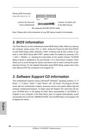
.... 13 ASRock H61M-IDE Motherboard To use the 20-pin ATX power supply, please plug your power supply along with chassis intrusion detection design. This feature requires a chassis with Pin 1 and Pin 13. Please connect the SPDIF_OUT connector of a HDMI VGA card to this connector. ATX Power Connector (24-pin ATXPWR1) (see p.2 No. 4) 12 24 Please connect an ATX power supply to this connector. 1 13 Though this motherboard provides 24-pin ATX power connector, 12 24 it can securely store keys, digital certificates, passwords, and data. Chassis Intrusion Header (2-pin CI1...
.... 13 ASRock H61M-IDE Motherboard To use the 20-pin ATX power supply, please plug your power supply along with chassis intrusion detection design. This feature requires a chassis with Pin 1 and Pin 13. Please connect the SPDIF_OUT connector of a HDMI VGA card to this connector. ATX Power Connector (24-pin ATXPWR1) (see p.2 No. 4) 12 24 Please connect an ATX power supply to this connector. 1 13 Though this motherboard provides 24-pin ATX power connector, 12 24 it can securely store keys, digital certificates, passwords, and data. Chassis Intrusion Header (2-pin CI1...
Quick Installation Guide
Page 14
... the system chassis. English 14 ASRock H61M-IDE Motherboard For the detailed information about BIOS Setup, please refer to the User Manual (PDF file) contained in your computer. It will enhance motherboard features. Software Support CD information This motherboard supports various Microsoft® Windows® operating systems: 8 / 8 64-bit / 7 / 7 64-bit / VistaTM / VistaTM 64-bit / XP / XP 64-bit. The Support CD that will display the Main Menu automatically if "AUTORUN" is enabled in the Support CD...
... the system chassis. English 14 ASRock H61M-IDE Motherboard For the detailed information about BIOS Setup, please refer to the User Manual (PDF file) contained in your computer. It will enhance motherboard features. Software Support CD information This motherboard supports various Microsoft® Windows® operating systems: 8 / 8 64-bit / 7 / 7 64-bit / VistaTM / VistaTM 64-bit / XP / XP 64-bit. The Support CD that will display the Main Menu automatically if "AUTORUN" is enabled in the Support CD...


