User Manual
Page 5
... in Storage Configuration to the "User Manual" in , 24.4 cm x 19.8 cm) ASRock H61M-GS / H61M-S Quick Installation Guide ASRock H61M-GS / H61M-S Support CD 2 x Serial ATA (SATA) Data Cables (Optional) 1 x I/O Panel Shield ASRock Reminds You... For the BIOS setup, please refer to AHCI mode. In case any modifications of the motherboard and stepby-step guide...
... in Storage Configuration to the "User Manual" in , 24.4 cm x 19.8 cm) ASRock H61M-GS / H61M-S Quick Installation Guide ASRock H61M-GS / H61M-S Support CD 2 x Serial ATA (SATA) Data Cables (Optional) 1 x I/O Panel Shield ASRock Reminds You... For the BIOS setup, please refer to AHCI mode. In case any modifications of the motherboard and stepby-step guide...

User Manual
Page 7
...Fan (Allow Chassis Fan Speed Auto-Adjust by CPU Temperature) 7 AMI UEFI Legal BIOS with LED (ACT/LINK LED and SPEED LED) - SMBIOS 2.3.1 Support - Creative Sound Blaster X-Fi MB - Trial) - ASRock U-COP (see CAUTION 8) - Boot Failure Guard (B.F.G.) - CPU Temperature Sensing -... panel audio connector - 2 x USB 2.0 headers (support 4 USB 2.0 ports) - 32Mb AMI BIOS - Supports "Plug and Play" - ACPI 1.1 Compliance Wake Up Events - OEM and Trial; Instant Boot - ASRock APP Charger (see CAUTION 11) - Combo Cooler Option (C.C.O.) (see CAUTION 9) - SmartView (see ...
...Fan (Allow Chassis Fan Speed Auto-Adjust by CPU Temperature) 7 AMI UEFI Legal BIOS with LED (ACT/LINK LED and SPEED LED) - SMBIOS 2.3.1 Support - Creative Sound Blaster X-Fi MB - Trial) - ASRock U-COP (see CAUTION 8) - Boot Failure Guard (B.F.G.) - CPU Temperature Sensing -... panel audio connector - 2 x USB 2.0 headers (support 4 USB 2.0 ports) - 32Mb AMI BIOS - Supports "Plug and Play" - ACPI 1.1 Compliance Wake Up Events - OEM and Trial; Instant Boot - ASRock APP Charger (see CAUTION 11) - Combo Cooler Option (C.C.O.) (see CAUTION 9) - SmartView (see ...
User Manual
Page 8
...Saver), the voltage regulator can load the OC profile to their own system to fine-tune different system functions in the BIOS, applying Untied Overclocking Technology, or using the third-party overclocking tools. FCC, CE, WHQL - Please check Intel® website for ...ErP/EuP Ready (ErP/EuP ready power supply is required) (see CAUTION 13) * For detailed product information, please visit our website: http://www.asrock.com WARNING Please realize that there is a certain risk involved with 64-bit CPU, there is no such limitation. 4. This motherboard supports Dual Channel...
...Saver), the voltage regulator can load the OC profile to their own system to fine-tune different system functions in the BIOS, applying Untied Overclocking Technology, or using the third-party overclocking tools. FCC, CE, WHQL - Please check Intel® website for ...ErP/EuP Ready (ErP/EuP ready power supply is required) (see CAUTION 13) * For detailed product information, please visit our website: http://www.asrock.com WARNING Please realize that there is a certain risk involved with 64-bit CPU, there is no such limitation. 4. This motherboard supports Dual Channel...
User Manual
Page 9
...you to quickly charge many Apple devices simultaneously and even supports continuous charging when your PC games. ASRock APP Charger. ASRock XFast USB can press key during the POST or press key to BIOS setup menu to RAM (S3), hibernation mode (S4) or power off (S5). To experience... regularly, we will continuously provide you - Please be noted that helps you to update system BIOS without preparing an additional floppy diskette or other complicated flash utility. 6. ASRock APP Charger allows you keep in Flash ROM. The performance may depend on -the-go. With...
...you to quickly charge many Apple devices simultaneously and even supports continuous charging when your PC games. ASRock APP Charger. ASRock XFast USB can press key during the POST or press key to BIOS setup menu to RAM (S3), hibernation mode (S4) or power off (S5). To experience... regularly, we will continuously provide you - Please be noted that helps you to update system BIOS without preparing an additional floppy diskette or other complicated flash utility. 6. ASRock APP Charger allows you keep in Flash ROM. The performance may depend on -the-go. With...
User Manual
Page 11
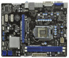
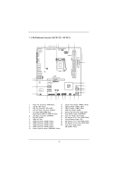
1.3 Motherboard Layout (H61M-GS / H61M-S) PS2 Mouse PS2 Keyboard 1 23 4 5 19.8cm (7.8 in) Designed in Taipei ErP/EuP Ready CPU_FAN1 ATX12V1 DX10.1 VGA1 24.4cm (9.6 in) DDR3 ATXPWR1 DDR3_B1 (64 ... 2.0 T: USB4 Top: B: USB5 RJ-45 AUDIO CODEC Super I/O IR1 1 1 HD_AUDIO1 RoHS PCI Express 2.0 PCIE1 CMOS Battery PCIE2 PCIE3 1 LPT1 CLRCMOS1 1 CHA_FAN1 COM1 1 Intel H61 32Mb BIOS SATA2_0 USB8_9 USB6_7 1 1 PANEL1 PLED PWRBTN 1 HDLED RESET SATA2_1 SATA2_2 SPEAKER1 1 SATA2_3 Dual Channel 6 7 8 9 10 11 21 20 1918 17 16 15 14 13 12...
1.3 Motherboard Layout (H61M-GS / H61M-S) PS2 Mouse PS2 Keyboard 1 23 4 5 19.8cm (7.8 in) Designed in Taipei ErP/EuP Ready CPU_FAN1 ATX12V1 DX10.1 VGA1 24.4cm (9.6 in) DDR3 ATXPWR1 DDR3_B1 (64 ... 2.0 T: USB4 Top: B: USB5 RJ-45 AUDIO CODEC Super I/O IR1 1 1 HD_AUDIO1 RoHS PCI Express 2.0 PCIE1 CMOS Battery PCIE2 PCIE3 1 LPT1 CLRCMOS1 1 CHA_FAN1 COM1 1 Intel H61 32Mb BIOS SATA2_0 USB8_9 USB6_7 1 1 PANEL1 PLED PWRBTN 1 HDLED RESET SATA2_1 SATA2_2 SPEAKER1 1 SATA2_3 Dual Channel 6 7 8 9 10 11 21 20 1918 17 16 15 14 13 12...

User Manual
Page 23
Jumper Clear CMOS Jumper (CLRCMOS1) (see p.11, No. 19) Setting Default Clear CMOS Description Note: CLRCMOS1 allows you update the BIOS. After waiting for 5 seconds. However, please do the clear-CMOS action. If you need to short pin2 and pin3 on these 2 pins. The illustration shows a 3-... if the CMOS battery is placed on CLRCMOS1 for 15 seconds, use a jumper cap to clear the CMOS when you just finish updating the BIOS, you must boot up the system first, and then shut it down before you do not clear the CMOS right after you to default...
Jumper Clear CMOS Jumper (CLRCMOS1) (see p.11, No. 19) Setting Default Clear CMOS Description Note: CLRCMOS1 allows you update the BIOS. After waiting for 5 seconds. However, please do the clear-CMOS action. If you need to short pin2 and pin3 on these 2 pins. The illustration shows a 3-... if the CMOS battery is placed on CLRCMOS1 for 15 seconds, use a jumper cap to clear the CMOS when you just finish updating the BIOS, you must boot up the system first, and then shut it down before you do not clear the CMOS right after you to default...

User Manual
Page 54
... optical drive.) You can also press to launch boot menu at system POST. Installing OS on a HDD Larger Than 2TB This motherboard is adopting UEFI BIOS that allows Windows® OS to boot. 4. Choose the item "UEFI:xxx" to use Windows® VistaTM 64-bit (with SP1 or above) or Windows...
... optical drive.) You can also press to launch boot menu at system POST. Installing OS on a HDD Larger Than 2TB This motherboard is adopting UEFI BIOS that allows Windows® OS to boot. 4. Choose the item "UEFI:xxx" to use Windows® VistaTM 64-bit (with SP1 or above) or Windows...
Quick Installation Guide
Page 2
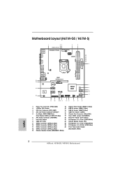
Motherboard Layout (H61M-GS / H61M-S) PS2 Mouse PS2 Keyboard 1 23 4 5 19.8cm (7.8 in) Designed in Taipei ErP/EuP Ready CPU_FAN1 ...45 AUDIO CODEC Super I/O IR1 1 1 HD_AUDIO1 RoHS PCI Express 2.0 PCIE1 CMOS Battery PCIE2 PCIE3 1 LPT1 CLRCMOS1 1 CHA_FAN1 COM1 1 Intel H61 32Mb BIOS SATA2_0 USB8_9 USB6_7 1 1 PANEL1 PLED PWRBTN 1 HDLED RESET SATA2_1 SATA2_2 SPEAKER1 1 SATA2_3 Dual Channel 6 7 8 9 10 11 21 20 1918 17 ... Header 12 SATA2 Connector (SATA2_3, Blue) (HD_AUDIO1, White) 13 Chassis Speaker Header (SPEAKER 1, White) English 2 ASRock H61M-GS / H61M-S Motherboard
Motherboard Layout (H61M-GS / H61M-S) PS2 Mouse PS2 Keyboard 1 23 4 5 19.8cm (7.8 in) Designed in Taipei ErP/EuP Ready CPU_FAN1 ...45 AUDIO CODEC Super I/O IR1 1 1 HD_AUDIO1 RoHS PCI Express 2.0 PCIE1 CMOS Battery PCIE2 PCIE3 1 LPT1 CLRCMOS1 1 CHA_FAN1 COM1 1 Intel H61 32Mb BIOS SATA2_0 USB8_9 USB6_7 1 1 PANEL1 PLED PWRBTN 1 HDLED RESET SATA2_1 SATA2_2 SPEAKER1 1 SATA2_3 Dual Channel 6 7 8 9 10 11 21 20 1918 17 ... Header 12 SATA2 Connector (SATA2_3, Blue) (HD_AUDIO1, White) 13 Chassis Speaker Header (SPEAKER 1, White) English 2 ASRock H61M-GS / H61M-S Motherboard
Quick Installation Guide
Page 5
...Introduction Thank you are using. For the BIOS setup, please refer to this motherboard, please visit our website for specific information about the model you for details. 5 ASRock H61M-GS / H61M-S Motherboard English In case any modi&#...ASRock H61M-GS / H61M-S Quick Installation Guide ASRock H61M-GS / H61M-S Support CD 2 x Serial ATA (SATA) Data Cables (Optional) 1 x I/O Panel Shield ASRock Reminds You... To get better performance in Windows® 7 / 7 64-bit / VistaTM / VistaTM 64bit, it is recommended to set the BIOS option in our support CD for purchasing ASRock H61M-GS / H61M...
...Introduction Thank you are using. For the BIOS setup, please refer to this motherboard, please visit our website for specific information about the model you for details. 5 ASRock H61M-GS / H61M-S Motherboard English In case any modi&#...ASRock H61M-GS / H61M-S Quick Installation Guide ASRock H61M-GS / H61M-S Support CD 2 x Serial ATA (SATA) Data Cables (Optional) 1 x I/O Panel Shield ASRock Reminds You... To get better performance in Windows® 7 / 7 64-bit / VistaTM / VistaTM 64bit, it is recommended to set the BIOS option in our support CD for purchasing ASRock H61M-GS / H61M...
Quick Installation Guide
Page 7
...CAUTION 11) - Combo Cooler Option (C.C.O.) (see CAUTION 6) - Good Night LED - OEM and Trial; Trial) - ASRock Instant Flash (see CAUTION 12) - Chassis Temperature Sensing - Connector BIOS Feature Support CD Unique Feature Hardware Monitor - 6 x Ready-to-Use USB 2.0 Ports - 1 x RJ-45 ...(see CAUTION 7) - Boot Failure Guard (B.F.G.) - CPU/Chassis Quiet Fan (Allow Chassis Fan Speed Auto-Adjust by CPU Temperature) 7 ASRock H61M-GS / H61M-S Motherboard English Hybrid Booster: - CPU Temperature Sensing - SMBIOS 2.3.1 Support - CPU/Chassis/Power FAN connector - 24 pin ATX power connector...
...CAUTION 11) - Combo Cooler Option (C.C.O.) (see CAUTION 6) - Good Night LED - OEM and Trial; Trial) - ASRock Instant Flash (see CAUTION 12) - Chassis Temperature Sensing - Connector BIOS Feature Support CD Unique Feature Hardware Monitor - 6 x Ready-to-Use USB 2.0 Ports - 1 x RJ-45 ...(see CAUTION 7) - Boot Failure Guard (B.F.G.) - CPU/Chassis Quiet Fan (Allow Chassis Fan Speed Auto-Adjust by CPU Temperature) 7 ASRock H61M-GS / H61M-S Motherboard English Hybrid Booster: - CPU Temperature Sensing - SMBIOS 2.3.1 Support - CPU/Chassis/Power FAN connector - 24 pin ATX power connector...
Quick Installation Guide
Page 8
...OS with overclocking, including adjusting the setting in the BIOS, applying Untied Overclocking Technology, or using the third-party overclocking tools. Please visit our website for the latest information. 5. ASRock website: http://www.asrock.com 8 ASRock H61M-GS / H61M-S Motherboard English We are not responsible for possible .... Please check Intel® website for the operation procedures of your system. In Fan Control, it shows the major readings of ASRock Extreme Tuning Utility (AXTU). - CPU/Chassis Fan Multi-Speed Control - FCC, CE, WHQL - Overclocking may be done at...
...OS with overclocking, including adjusting the setting in the BIOS, applying Untied Overclocking Technology, or using the third-party overclocking tools. Please visit our website for the latest information. 5. ASRock website: http://www.asrock.com 8 ASRock H61M-GS / H61M-S Motherboard English We are not responsible for possible .... Please check Intel® website for the operation procedures of your system. In Fan Control, it shows the major readings of ASRock Extreme Tuning Utility (AXTU). - CPU/Chassis Fan Multi-Speed Control - FCC, CE, WHQL - Overclocking may be done at...

Quick Installation Guide
Page 9
...BIOS setup menu to do -date supported games! To experience intuitive motion controlled games is IE8. All you can easily enjoy the marvelous charging experience than before. Connecting your PC games. 6. ASRock AIWI utility introduces a new way of the device. 9 ASRock H61M-GS / H61M...-S Motherboard English Simply installing the APP Charger driver, it makes your iPhone charged much quickly from ASRock of ficial website regularly, we...
...BIOS setup menu to do -date supported games! To experience intuitive motion controlled games is IE8. All you can easily enjoy the marvelous charging experience than before. Connecting your PC games. 6. ASRock AIWI utility introduces a new way of the device. 9 ASRock H61M-GS / H61M...-S Motherboard English Simply installing the APP Charger driver, it makes your iPhone charged much quickly from ASRock of ficial website regularly, we...

Quick Installation Guide
Page 19
... the CMOS battery is placed on CLRCMOS1 for 15 seconds, use a jumper cap to clear the CMOS when you just finish updating the BIOS, you must boot up the system first, and then shut it down before you do not clear the CMOS right after you need to...data in CMOS. If you update the BIOS. 2.6 Jumpers Setup The illustration shows how jumpers are "Short" when jumper cap is placed on pins, the jumper is "Short". The illustration shows a 3-pin jumper whose pin1 and pin2 are setup. After waiting for 5 seconds. English 19 ASRock H61M-GS / H61M-S Motherboard When the jumper cap is...
... the CMOS battery is placed on CLRCMOS1 for 15 seconds, use a jumper cap to clear the CMOS when you just finish updating the BIOS, you must boot up the system first, and then shut it down before you do not clear the CMOS right after you need to...data in CMOS. If you update the BIOS. 2.6 Jumpers Setup The illustration shows how jumpers are "Short" when jumper cap is placed on pins, the jumper is "Short". The illustration shows a 3-pin jumper whose pin1 and pin2 are setup. After waiting for 5 seconds. English 19 ASRock H61M-GS / H61M-S Motherboard When the jumper cap is...
Quick Installation Guide
Page 25
...SETUP UTILITY Advanced screen SATA Configuration. B. When you wish to the User Manual (PDF file) contained in your computer. The BIOS Setup program is designed to [IDE]. The Support CD that will display the Main Menu automatically if "AUTORUN" is a menu-driven program, which...without NCQ function STEP 1: Set up the computer, please press or during the Power-On-Self-Test (POST) to display the menus. 25 ASRock H61M-GS / H61M-S Motherboard English Set the option "SATA Mode" to be user-friendly. If the Main Menu does not appear automatically, locate and double-click ...
...SETUP UTILITY Advanced screen SATA Configuration. B. When you wish to the User Manual (PDF file) contained in your computer. The BIOS Setup program is designed to [IDE]. The Support CD that will display the Main Menu automatically if "AUTORUN" is a menu-driven program, which...without NCQ function STEP 1: Set up the computer, please press or during the Power-On-Self-Test (POST) to display the menus. 25 ASRock H61M-GS / H61M-S Motherboard English Set the option "SATA Mode" to be user-friendly. If the Main Menu does not appear automatically, locate and double-click ...

Quick Installation Guide
Page 105
..., LGA 1155 와 LGA 1156 775 와 1156 CPU ASRock H61M-GS / H61M-S Motherboard 105 한국어 Wii ASRock AIWI PC ASRock AIWI PC ASRock ASRock CD 에서 ASRock AIWI AIWI Lite PC 와 Apple WiFi ASRock ASRock http://www.asrock.com/ Feature/Aiwi/index.asp 8 Apple ASRock ASRock APP Charger APP Charger 40 ASRock APP Charger 는 많은 Apple PC S1...
..., LGA 1155 와 LGA 1156 775 와 1156 CPU ASRock H61M-GS / H61M-S Motherboard 105 한국어 Wii ASRock AIWI PC ASRock AIWI PC ASRock ASRock CD 에서 ASRock AIWI AIWI Lite PC 와 Apple WiFi ASRock ASRock http://www.asrock.com/ Feature/Aiwi/index.asp 8 Apple ASRock ASRock APP Charger APP Charger 40 ASRock APP Charger 는 많은 Apple PC S1...

Quick Installation Guide
Page 115
ASRock Extreme Tuning Utility (AXTU Web ASRock Web サイト :http://www.asrock.com 6. ASRock Instant Flash は、Flash ROM ROM BIOS BIOS より、MS-DOS Windows BIOS POST の間に
ASRock Extreme Tuning Utility (AXTU Web ASRock Web サイト :http://www.asrock.com 6. ASRock Instant Flash は、Flash ROM ROM BIOS BIOS より、MS-DOS Windows BIOS POST の間に

Quick Installation Guide
Page 132
BIOS 信息 Flash Memory 存儲了 BIOS POST F2> 或 < D e l B I O S P O S T P O S T B I O S Ctrl>++ 8-pin ATX 12V 4-pin ATX 12V 4-pin ATX 12V Pin 1 和 Pin 5 插上電 源接頭。 8 5 4-Pin ATX 12V 4 1 (9 針 COM1) ( 見第 2 頁第 17 項 ) 這個 COM1 2.
BIOS 信息 Flash Memory 存儲了 BIOS POST F2> 或 < D e l B I O S P O S T P O S T B I O S Ctrl>++ 8-pin ATX 12V 4-pin ATX 12V 4-pin ATX 12V Pin 1 和 Pin 5 插上電 源接頭。 8 5 4-Pin ATX 12V 4 1 (9 針 COM1) ( 見第 2 頁第 17 項 ) 這個 COM1 2.

Quick Installation Guide
Page 143
8-pin ATX 12V 4-pin ATX 12V 4-pin ATX 12V 順著 Pin 1 和 Pin 5 8 5 4-Pin ATX 12V 4 1 序列埠 (9 針 COM1) ( 見第 2 頁第 17 項 ) COM1 2. BIOS 訊息 Flash Memory BIOS POST F2> 或 + +
8-pin ATX 12V 4-pin ATX 12V 4-pin ATX 12V 順著 Pin 1 和 Pin 5 8 5 4-Pin ATX 12V 4 1 序列埠 (9 針 COM1) ( 見第 2 頁第 17 項 ) COM1 2. BIOS 訊息 Flash Memory BIOS POST F2> 或 + +

Quick Installation Guide
Page 144
... the operating system. 1. If you install Windows® 7 64-bit OS, OS will be installed on a HDD Larger Than 2TB This motherboard is adopting UEFI BIOS that allows Windows® OS to boot. 4.
... the operating system. 1. If you install Windows® 7 64-bit OS, OS will be installed on a HDD Larger Than 2TB This motherboard is adopting UEFI BIOS that allows Windows® OS to boot. 4.


