
User Manual
Page 3
...Motherboard Layout 13 1.5 I/O Panel 14 2 Installation 15 2.1 Screw Holes 15 2.2 Pre-installation Precautions 15 2.3 CPU Installation 16 2.4 Installation of Heatsink and CPU fan 18 2.5 Installation of Memory Modules (DIMM 19 2.6 Expansion Slots (PCI Express Slots 20 2.7 Dual Monitor and Surround Display Features 21 2.8 Jumpers Setup 24 2.9 Onboard Headers and Connectors 25 2.10 Serial ATA (SATA) / Serial ATAII (SATAII) Hard Disks Installation 29 2.11 Hot Plug Function for SATA / SATAII HDDs 29 2.12 SATA / SATAII HDD Hot Plug Feature and Operation Guide 30 2.13 Driver Installation...
...Motherboard Layout 13 1.5 I/O Panel 14 2 Installation 15 2.1 Screw Holes 15 2.2 Pre-installation Precautions 15 2.3 CPU Installation 16 2.4 Installation of Heatsink and CPU fan 18 2.5 Installation of Memory Modules (DIMM 19 2.6 Expansion Slots (PCI Express Slots 20 2.7 Dual Monitor and Surround Display Features 21 2.8 Jumpers Setup 24 2.9 Onboard Headers and Connectors 25 2.10 Serial ATA (SATA) / Serial ATAII (SATAII) Hard Disks Installation 29 2.11 Hot Plug Function for SATA / SATAII HDDs 29 2.12 SATA / SATAII HDD Hot Plug Feature and Operation Guide 30 2.13 Driver Installation...

User Manual
Page 4
...Screen 41 3.4.1 CPU Configuration 42 3.4.2 North Bridge Configuration 44 3.4.3 South Bridge Configuration 45 3.4.4 Storage Configuration 46 3.4.5 Intel(R) Rapid Start Technology 47 3.4.6 Intel(R) Smart Connect Technology 48 3.4.7 Super IO Configuration 49 3.4.8 ACPI Configuration 50 3.4.9 USB Configuration 51 3.4.10 Network Configuration 52 3.5 Hardware Health Event Monitoring Screen 53 3.6 Boot Screen 54 3.7 Security Screen 55 3.8 Exit Screen 56 4 Software Support 57 4.1 Install Operating System 57 4.2 Support CD Information 57 4.2.1 Running Support CD 57 4.2.2 Drivers Menu...
...Screen 41 3.4.1 CPU Configuration 42 3.4.2 North Bridge Configuration 44 3.4.3 South Bridge Configuration 45 3.4.4 Storage Configuration 46 3.4.5 Intel(R) Rapid Start Technology 47 3.4.6 Intel(R) Smart Connect Technology 48 3.4.7 Super IO Configuration 49 3.4.8 ACPI Configuration 50 3.4.9 USB Configuration 51 3.4.10 Network Configuration 52 3.5 Hardware Health Event Monitoring Screen 53 3.6 Boot Screen 54 3.7 Security Screen 55 3.8 Exit Screen 56 4 Software Support 57 4.1 Install Operating System 57 4.2 Support CD Information 57 4.2.1 Running Support CD 57 4.2.2 Drivers Menu...
User Manual
Page 5
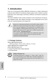
... quality control. www.asrock.com/support/index.asp 1.1 Package Contents ASRock H61 Pro Motherboard (ATX Form Factor: 12.0-in x 6.8-in Storage Configuration to change without further notice. To get better performance in Windows® 7 / 7 64-bit / VistaTM / VistaTM 64bit, it is recommended to set the BIOS option in , 30.5 cm x 17.3 cm) ASRock H61 Pro Quick Installation Guide ASRock H61 Pro Support CD 2 x Serial ATA (SATA) Data Cables (Optional) 1 x I/O Panel Shield ASRock Reminds You... Because the motherboard specifications and the BIOS software might be updated, the...
... quality control. www.asrock.com/support/index.asp 1.1 Package Contents ASRock H61 Pro Motherboard (ATX Form Factor: 12.0-in x 6.8-in Storage Configuration to change without further notice. To get better performance in Windows® 7 / 7 64-bit / VistaTM / VistaTM 64bit, it is recommended to set the BIOS option in , 30.5 cm x 17.3 cm) ASRock H61 Pro Quick Installation Guide ASRock H61 Pro Support CD 2 x Serial ATA (SATA) Data Cables (Optional) 1 x I/O Panel Shield ASRock Reminds You... Because the motherboard specifications and the BIOS software might be updated, the...

User Manual
Page 6
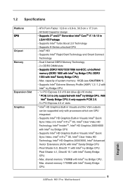
1.2 Specifications Platform CPU Chipset Memory Expansion Slot Graphics - Supports K-Series unlocked CPU - Supports DDR3 1600/1333/1066 non-ECC, un-buffered memory (DDR3 1600 with Intel® Ivy Bridge CPU, DDR3 1333 with Intel® Sandy Bridge CPU. 6 With Intel® Sandy Bridge CPU, it only supports PCIE 2.0. - 5 x PCI Express 2.0 x1 slots * Intel® HD Graphics Built-in Visuals: Intel® Quick Sync Video, Intel® InTruTM 3D, Intel® Clear Video HD Technology, Intel...
1.2 Specifications Platform CPU Chipset Memory Expansion Slot Graphics - Supports K-Series unlocked CPU - Supports DDR3 1600/1333/1066 non-ECC, un-buffered memory (DDR3 1600 with Intel® Ivy Bridge CPU, DDR3 1333 with Intel® Sandy Bridge CPU. 6 With Intel® Sandy Bridge CPU, it only supports PCIE 2.0. - 5 x PCI Express 2.0 x1 slots * Intel® HD Graphics Built-in Visuals: Intel® Quick Sync Video, Intel® InTruTM 3D, Intel® Clear Video HD Technology, Intel...

User Manual
Page 10
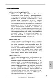
... Monitor, Fan Control, Overclocking, OC DNA, IES and XFast RAM. Just launch this utility, you to adjust. In Hardware Monitor, it shows the fan speed and temperature for your system. 1.3 Unique Features ASRock Extreme Tuning Utility (AXTU) ASRock Extreme Tuning Utility (AXTU) is a BIOS flash utility embedded in just a few seconds, provides a much more efficient way to save the new BIOS file to your USB flash drive, floppy disk or hard drive, then you to enter your Windows...
... Monitor, Fan Control, Overclocking, OC DNA, IES and XFast RAM. Just launch this utility, you to adjust. In Hardware Monitor, it shows the fan speed and temperature for your system. 1.3 Unique Features ASRock Extreme Tuning Utility (AXTU) ASRock Extreme Tuning Utility (AXTU) is a BIOS flash utility embedded in just a few seconds, provides a much more efficient way to save the new BIOS file to your USB flash drive, floppy disk or hard drive, then you to enter your Windows...

User Manual
Page 13
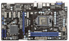
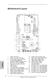
...) 3 ATX 12V Power Connector (ATX12V1) 17 USB 2.0 Header (USB8_9, Blue) 4 2 x 240-pin DDR3 DIMM Slots 18 USB 2.0 Header (USB6_7, Blue) (Dual Channel: DDR3_A1, DDR3_B1, Blue) 19 COM Port Header (COM1) 5 ATX Power Connector (ATXPWR1) 20 Front Panel Audio Header 6 Chassis Fan Connector (CHA_FAN1) (HD_AUDIO1, White) 7 32Mb SPI Flash 21 PCI Express 2.0 x1 Slot (PCIE6, White) 8 Intel H61 Chipset 22 PCI Express 2.0 x1 Slot (PCIE5, White) 9 Clear CMOS Jumper (CLRCMOS1) 23 PCI Express 2.0 x1 Slot (PCIE4, White) 10 Chassis Speaker Header (SPEAKER 1, White) 24 PCI Express 2.0 x1 Slot...
...) 3 ATX 12V Power Connector (ATX12V1) 17 USB 2.0 Header (USB8_9, Blue) 4 2 x 240-pin DDR3 DIMM Slots 18 USB 2.0 Header (USB6_7, Blue) (Dual Channel: DDR3_A1, DDR3_B1, Blue) 19 COM Port Header (COM1) 5 ATX Power Connector (ATXPWR1) 20 Front Panel Audio Header 6 Chassis Fan Connector (CHA_FAN1) (HD_AUDIO1, White) 7 32Mb SPI Flash 21 PCI Express 2.0 x1 Slot (PCIE6, White) 8 Intel H61 Chipset 22 PCI Express 2.0 x1 Slot (PCIE5, White) 9 Clear CMOS Jumper (CLRCMOS1) 23 PCI Express 2.0 x1 Slot (PCIE4, White) 10 Chassis Speaker Header (SPEAKER 1, White) 24 PCI Express 2.0 x1 Slot...
User Manual
Page 21
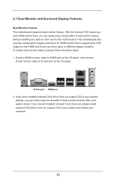
... connect D-Sub monitor cable to support dual VGA output so that HDMI and D-sub can drive same or different display contents. D-Sub port HDMI port 2. 2.7 Dual Monitor and Surround Display Features Dual Monitor Feature This motherboard supports dual monitor feature. This motherboard also provides independent display controllers for HDMI and D-Sub to D-Sub port on VGA card to your system and restart your system boots. If you have installed onboard VGA driver from our support CD to this motherboard. If you haven't installed onboard VGA driver yet, please install onboard VGA driver...
... connect D-Sub monitor cable to support dual VGA output so that HDMI and D-sub can drive same or different display contents. D-Sub port HDMI port 2. 2.7 Dual Monitor and Surround Display Features Dual Monitor Feature This motherboard supports dual monitor feature. This motherboard also provides independent display controllers for HDMI and D-Sub to D-Sub port on VGA card to your system and restart your system boots. If you have installed onboard VGA driver from our support CD to this motherboard. If you haven't installed onboard VGA driver yet, please install onboard VGA driver...

User Manual
Page 22
... PCI Express VGA card on VGA card is no need to the corresponding connectors of "Onboard VGA Share Memory", [Auto], will be your card, one , two, three and four. 22 Right-click the display icon and select "Attached", if necessary. F. G. Then connect other monitor cables to install them again. 5. If you have installed the drivers already, there is inserted to the steps below. Install the onboard VGA driver and the add-on PCIE2 slot. D. Enter "Onboard VGA...
... PCI Express VGA card on VGA card is no need to the corresponding connectors of "Onboard VGA Share Memory", [Auto], will be your card, one , two, three and four. 22 Right-click the display icon and select "Attached", if necessary. F. G. Then connect other monitor cables to install them again. 5. If you have installed the drivers already, there is inserted to the steps below. Install the onboard VGA driver and the add-on PCIE2 slot. D. Enter "Onboard VGA...

User Manual
Page 32
... use an USB floppy or a floppy disk.) A. E. Insert the Support CD into the floppy drive, and press . B. Enter UEFI SETUP UTILITY Advanced screen SATA Configuration. During POST at the beginning of system boot-up to bottom side to install those required drivers. Please insert a floppy diskette into your optical drive to boot your SATA / SATAII HDDs without RAID functions, please follow below steps. Therefore, the drivers you install can be auto-detected and listed on the support CD driver page. Start to [AHCI]. Set...
... use an USB floppy or a floppy disk.) A. E. Insert the Support CD into the floppy drive, and press . B. Enter UEFI SETUP UTILITY Advanced screen SATA Configuration. During POST at the beginning of system boot-up to bottom side to install those required drivers. Please insert a floppy diskette into your optical drive to boot your SATA / SATAII HDDs without RAID functions, please follow below steps. Therefore, the drivers you install can be auto-detected and listed on the support CD driver page. Start to [AHCI]. Set...

User Manual
Page 42
... technology. The default value is [Auto]. In the C1 power state, the processor maintains the context of cores to select the number of the system caches. CPU C6 State Support Use this to enable or disable CPU C3 (ACPI C2) report to OS. The default value is [All]. CPU C3 State Support Use this to enable or disable CPU C6 (ACPI C3) report to OS. Active Processor Cores Use this technology, such as Microsoft® Windows...
... technology. The default value is [Auto]. In the C1 power state, the processor maintains the context of cores to select the number of the system caches. CPU C6 State Support Use this to enable or disable CPU C3 (ACPI C2) report to OS. The default value is [All]. CPU C3 State Support Use this to enable or disable CPU C6 (ACPI C3) report to OS. Active Processor Cores Use this technology, such as Microsoft® Windows...

User Manual
Page 44
... Speed This allows you install the PCI Express card under Windows® XP / VistaTM OS, please disable this to enable or disable Intel® VT-d technology (Intel® Virtualization Technology for Directed I/O). Render Standby Use this option. The default value of this to enable or disable Render Standby by Internal Graphics Device. The default value is [Disabled]. VT-d Use this feature is [Enabled]. If you to enable or disable IGPU Multi-Moniter. The default value is [PCI Express]. Share Memory...
... Speed This allows you install the PCI Express card under Windows® XP / VistaTM OS, please disable this to enable or disable Intel® VT-d technology (Intel® Virtualization Technology for Directed I/O). Render Standby Use this option. The default value of this to enable or disable Render Standby by Internal Graphics Device. The default value is [Disabled]. VT-d Use this feature is [Enabled]. If you to enable or disable IGPU Multi-Moniter. The default value is [PCI Express]. Share Memory...

User Manual
Page 51
...legacy support for USB devices. USB devices are connected. [Disabled] - The default value is recommended to select [Disabled] to enable or disable the use of these four options: [Enabled] - Enables legacy support if USB devices are allowed to use only under legacy OS and UEFI setup when [Disabled] is selected. There are not allowed to use under UEFI setup and Windows / Linux OS. 51 USB devices are four configuration options: [Enabled], [Auto], [Disabled] and [UEFI Setup Only]. Legacy USB Support Use this item to enter OS. [UEFI Setup Only] - If you have USB compatibility...
...legacy support for USB devices. USB devices are connected. [Disabled] - The default value is recommended to select [Disabled] to enable or disable the use of these four options: [Enabled] - Enables legacy support if USB devices are allowed to use only under legacy OS and UEFI setup when [Disabled] is selected. There are not allowed to use under UEFI setup and Windows / Linux OS. 51 USB devices are four configuration options: [Enabled], [Auto], [Disabled] and [UEFI Setup Only]. Legacy USB Support Use this item to enter OS. [UEFI Setup Only] - If you have USB compatibility...
User Manual
Page 57
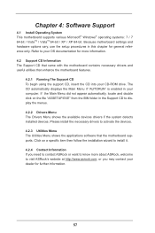
... the devices. 4.2.3 Utilities Menu The Utilities Menu shows the applications software that enhance the motherboard features. 4.2.1 Running The Support CD To begin using the support CD, insert the CD into your OS documentation for more about ASRock, welcome to display the menus. 4.2.2 Drivers Menu The Drivers Menu shows the available devices drivers if the system detects installed devices. Please install the necessary drivers to your CD-ROM drive. Because motherboard settings and hardware options vary, use the setup procedures...
... the devices. 4.2.3 Utilities Menu The Utilities Menu shows the applications software that enhance the motherboard features. 4.2.1 Running The Support CD To begin using the support CD, insert the CD into your OS documentation for more about ASRock, welcome to display the menus. 4.2.2 Drivers Menu The Drivers Menu shows the available devices drivers if the system detects installed devices. Please install the necessary drivers to your CD-ROM drive. Because motherboard settings and hardware options vary, use the setup procedures...
Quick Installation Guide
Page 2
...) 3 ATX 12V Power Connector (ATX12V1) 17 USB 2.0 Header (USB8_9, Blue) 4 2 x 240-pin DDR3 DIMM Slots 18 USB 2.0 Header (USB6_7, Blue) (Dual Channel: DDR3_A1, DDR3_B1, Blue) 19 COM Port Header (COM1) 5 ATX Power Connector (ATXPWR1) 20 Front Panel Audio Header 6 Chassis Fan Connector (CHA_FAN1) (HD_AUDIO1, White) 7 32Mb SPI Flash 21 PCI Express 2.0 x1 Slot (PCIE6, White) 8 Intel H61 Chipset 22 PCI Express 2.0 x1 Slot (PCIE5, White) 9 Clear CMOS Jumper (CLRCMOS1) 23 PCI Express 2.0 x1 Slot (PCIE4, White) 10 Chassis Speaker Header (SPEAKER 1, White) 24 PCI Express 2.0 x1 Slot...
...) 3 ATX 12V Power Connector (ATX12V1) 17 USB 2.0 Header (USB8_9, Blue) 4 2 x 240-pin DDR3 DIMM Slots 18 USB 2.0 Header (USB6_7, Blue) (Dual Channel: DDR3_A1, DDR3_B1, Blue) 19 COM Port Header (COM1) 5 ATX Power Connector (ATXPWR1) 20 Front Panel Audio Header 6 Chassis Fan Connector (CHA_FAN1) (HD_AUDIO1, White) 7 32Mb SPI Flash 21 PCI Express 2.0 x1 Slot (PCIE6, White) 8 Intel H61 Chipset 22 PCI Express 2.0 x1 Slot (PCIE5, White) 9 Clear CMOS Jumper (CLRCMOS1) 23 PCI Express 2.0 x1 Slot (PCIE4, White) 10 Chassis Speaker Header (SPEAKER 1, White) 24 PCI Express 2.0 x1 Slot...
Quick Installation Guide
Page 4
... set the BIOS option in the Support CD. 1. www.asrock.com/support/index.asp 1.1 Package Contents ASRock H61 Pro Motherboard (ATX Form Factor: 12.0-in x 6.8-in our support CD for purchasing ASRock H61 Pro motherboard, a reliable motherboard produced under ASRock's consistently stringent quality control. You may find the latest VGA cards and CPU support lists on ASRock website without notice. For the BIOS setup, please refer to the "User Manual" in , 30.5 cm x 17.3 cm) ASRock H61 Pro Quick Installation Guide ASRock H61 Pro Support CD 2 x Serial ATA (SATA) Data Cables (Optional...
... set the BIOS option in the Support CD. 1. www.asrock.com/support/index.asp 1.1 Package Contents ASRock H61 Pro Motherboard (ATX Form Factor: 12.0-in x 6.8-in our support CD for purchasing ASRock H61 Pro motherboard, a reliable motherboard produced under ASRock's consistently stringent quality control. You may find the latest VGA cards and CPU support lists on ASRock website without notice. For the BIOS setup, please refer to the "User Manual" in , 30.5 cm x 17.3 cm) ASRock H61 Pro Quick Installation Guide ASRock H61 Pro Support CD 2 x Serial ATA (SATA) Data Cables (Optional...
Quick Installation Guide
Page 5
Supports Intel® Rapid Start Technology and Smart Connect Technology - Dual Channel DDR3 Memory Technology - 2 x DDR3 DIMM slots - Pixel Shader 4.1, DirectX 10.1 with Intel® Sandy Bridge CPU. shared memory 1759MB with Intel® Sandy Bridge CPU. - 1.2 Specifications Platform CPU Chipset Memory Expansion Slot Graphics - Max. Max. Max. Supports Intel® Turbo Boost 2.0 Technology - Supports DDR3 1600/1333/1066 non-ECC, un-buffered memory (DDR3 1600 with Intel® Ivy Bridge CPU, DDR3 1333 with processors which are GPU integrated...
Supports Intel® Rapid Start Technology and Smart Connect Technology - Dual Channel DDR3 Memory Technology - 2 x DDR3 DIMM slots - Pixel Shader 4.1, DirectX 10.1 with Intel® Sandy Bridge CPU. shared memory 1759MB with Intel® Sandy Bridge CPU. - 1.2 Specifications Platform CPU Chipset Memory Expansion Slot Graphics - Max. Max. Max. Supports Intel® Turbo Boost 2.0 Technology - Supports DDR3 1600/1333/1066 non-ECC, un-buffered memory (DDR3 1600 with Intel® Ivy Bridge CPU, DDR3 1333 with processors which are GPU integrated...
Quick Installation Guide
Page 7
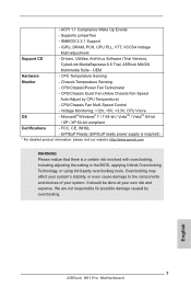
.... English 7 ASRock H61 Pro Motherboard - ACPI 1.1 Compliance Wake Up Events - CPU/Chassis/Power Fan Tachometer - We are not responsible for possible damage caused by CPU Temperature) - CPU Temperature Sensing Monitor - CPU/Chassis Fan Multi-Speed Control - SMBIOS 2.3.1 Support - Drivers, Utilities, AntiVirus Software (Trial Version), CyberLink MediaEspresso 6.5 Trial, ASRock MAGIX Multimedia Suite - Overclocking may affect your system's stability, or even cause damage to the components and devices of your own risk and expense. Voltage Monitoring: +12V...
.... English 7 ASRock H61 Pro Motherboard - ACPI 1.1 Compliance Wake Up Events - CPU/Chassis/Power Fan Tachometer - We are not responsible for possible damage caused by CPU Temperature) - CPU Temperature Sensing Monitor - CPU/Chassis Fan Multi-Speed Control - SMBIOS 2.3.1 Support - Drivers, Utilities, AntiVirus Software (Trial Version), CyberLink MediaEspresso 6.5 Trial, ASRock MAGIX Multimedia Suite - Overclocking may affect your system's stability, or even cause damage to the components and devices of your own risk and expense. Voltage Monitoring: +12V...
Quick Installation Guide
Page 9
... and S4 at specific timing during the POST or the key to enter into the BIOS setup menu to adjust. In Fan Control, it fully utilizes the memory space that the USB flash drive or hard drive must use FAT32/16/12 file system. 9 ASRock H61 Pro Motherboard English In OC DNA, you can reduce the number of your system. ASRock Instant Flash ASRock Instant Flash is an all-in-one tool to shorten boot up time...
... and S4 at specific timing during the POST or the key to enter into the BIOS setup menu to adjust. In Fan Control, it fully utilizes the memory space that the USB flash drive or hard drive must use FAT32/16/12 file system. 9 ASRock H61 Pro Motherboard English In OC DNA, you can reduce the number of your system. ASRock Instant Flash ASRock Instant Flash is an all-in-one tool to shorten boot up time...
Quick Installation Guide
Page 22
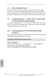
... OS on your SATA / SATAII HDDs without NCQ function STEP 1: Set up to bottom side to install Windows® XP / XP 64-bit OS on the support CD driver page. A. Set the option "SATA Mode Selection" to your optical drive first. STEP 2: Install Windows® XP / XP 64-bit OS on your system. 22 ASRock H61 Pro Motherboard English Using SATA / SATAII HDDs without RAID functions, please follow below steps. 2.7 Driver Installation Guide To install the drivers to your...
... OS on your SATA / SATAII HDDs without NCQ function STEP 1: Set up to bottom side to install Windows® XP / XP 64-bit OS on the support CD driver page. A. Set the option "SATA Mode Selection" to your optical drive first. STEP 2: Install Windows® XP / XP 64-bit OS on your system. 22 ASRock H61 Pro Motherboard English Using SATA / SATAII HDDs without RAID functions, please follow below steps. 2.7 Driver Installation Guide To install the drivers to your...
Quick Installation Guide
Page 24
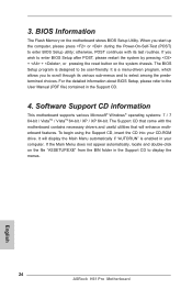
... + + , or pressing the reset button on the system chassis. For the detailed information about BIOS Setup, please refer to the User Manual (PDF file) contained in the Support CD to be user-friendly. If the Main Menu does not appear automatically, locate and double-click on the motherboard stores BIOS Setup Utility. It is designed to display the menus. 24 ASRock H61 Pro Motherboard English If you to enter BIOS Setup utility; When you start up the computer...
... + + , or pressing the reset button on the system chassis. For the detailed information about BIOS Setup, please refer to the User Manual (PDF file) contained in the Support CD to be user-friendly. If the Main Menu does not appear automatically, locate and double-click on the motherboard stores BIOS Setup Utility. It is designed to display the menus. 24 ASRock H61 Pro Motherboard English If you to enter BIOS Setup utility; When you start up the computer...


