
User Manual
Page 3
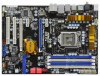
... Card Support List 11 1.4 Motherboard Layout 12 1.5 I/O Panel 13 2 Installation 15 2.1 Screw Holes 15 2.2 Pre-installation Precautions 15 2.3 CPU Installation 16 2.4 Installation of Heatsink and CPU fan 18 2.5 Installation of Memory Modules (DIMM 19 2.6 Expansion Slots (PCI and PCI Express Slots 21 2.7 CrossFireXTM and Quad CrossFireXTM Operation Guide 22 2.8 Surround Display Feature 26 2.9 Jumpers Setup 26 2.10 Onboard Headers and Connectors 27 2.11 Smart Switches 32 2.12 Dr. Debug 33 2.13 HDMI_SPDIF Header Connection Guide 36 2.14 SATAII Hard Disk Setup Guide 37 2.15 Serial...
... Card Support List 11 1.4 Motherboard Layout 12 1.5 I/O Panel 13 2 Installation 15 2.1 Screw Holes 15 2.2 Pre-installation Precautions 15 2.3 CPU Installation 16 2.4 Installation of Heatsink and CPU fan 18 2.5 Installation of Memory Modules (DIMM 19 2.6 Expansion Slots (PCI and PCI Express Slots 21 2.7 CrossFireXTM and Quad CrossFireXTM Operation Guide 22 2.8 Surround Display Feature 26 2.9 Jumpers Setup 26 2.10 Onboard Headers and Connectors 27 2.11 Smart Switches 32 2.12 Dr. Debug 33 2.13 HDMI_SPDIF Header Connection Guide 36 2.14 SATAII Hard Disk Setup Guide 37 2.15 Serial...

User Manual
Page 9
... Flash ROM. You can save your hardware devices to update system BIOS without preparing an additional floppy diskette or other than the recommended CPU bus frequencies may cause the instability of overclocking settings. ASRock website: http://www.asrock.com/feature/IES/index.html 12. Although this motherboard offers stepless control, it is a BIOS flash utility embedded in a few clicks without entering operating systems first like MS-DOS or Windows®. ASRock...
... Flash ROM. You can save your hardware devices to update system BIOS without preparing an additional floppy diskette or other than the recommended CPU bus frequencies may cause the instability of overclocking settings. ASRock website: http://www.asrock.com/feature/IES/index.html 12. Although this motherboard offers stepless control, it is a BIOS flash utility embedded in a few clicks without entering operating systems first like MS-DOS or Windows®. ASRock...
User Manual
Page 12
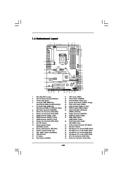
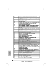
... Chassis Fan Connector (CHA_FAN3) 13 Intel H55 Chipset 14 Chassis Speaker Header (SPEAKER 1, Purple) 15 Primary IDE Connector (IDE1, Blue) 16 Chassis Intrusion Header (CI1) 17 Clear CMOS Jumper (CLRCMOS1) 18 16Mb SPI Flash 19 Dr. Debug 20 Reset Switch (RSTBTN) 21 TPM Header (TPM1) 22 Power Switch (PWRBTN) 23 Infrared Module Header (IR1) 24 System Panel Header (PANEL1, Orange) 25 Power LED Header (PLED1) 26 USB 2.0 Header (USB10_11, Blue) 27 USB 2.0 Header (USB8_9, Blue) 28 Front Panel IEEE 1394 Header (FRONT_1394, Red) 29 Floppy Connector...
... Chassis Fan Connector (CHA_FAN3) 13 Intel H55 Chipset 14 Chassis Speaker Header (SPEAKER 1, Purple) 15 Primary IDE Connector (IDE1, Blue) 16 Chassis Intrusion Header (CI1) 17 Clear CMOS Jumper (CLRCMOS1) 18 16Mb SPI Flash 19 Dr. Debug 20 Reset Switch (RSTBTN) 21 TPM Header (TPM1) 22 Power Switch (PWRBTN) 23 Infrared Module Header (IR1) 24 System Panel Header (PANEL1, Orange) 25 Power LED Header (PLED1) 26 USB 2.0 Header (USB10_11, Blue) 27 USB 2.0 Header (USB8_9, Blue) 28 Front Panel IEEE 1394 Header (FRONT_1394, Red) 29 Floppy Connector...

User Manual
Page 13
...) USB 2.0 Ports (USB45) USB 2.0 Ports (USB23) USB 2.0 Ports (USB01) Powered eSATAII/USB Connector Optical SPDIF Out Port Clear CMOS Switch (CLRCBTN) PS/2 Keyboard Port (Purple) * There are two LED next to the table below for connection details in accordance with the type of speaker you use . LAN Port LED Indications Activity/Link LED SPEED LED Status Description Status Description ACT/LINK SPEED LED LED Off No Link Off 10Mbps connection Blinking Data Activity Orange 100Mbps connection On Link Green 1Gbps connection LAN Port ** If you use 2-channel speaker...
...) USB 2.0 Ports (USB45) USB 2.0 Ports (USB23) USB 2.0 Ports (USB01) Powered eSATAII/USB Connector Optical SPDIF Out Port Clear CMOS Switch (CLRCBTN) PS/2 Keyboard Port (Purple) * There are two LED next to the table below for connection details in accordance with the type of speaker you use . LAN Port LED Indications Activity/Link LED SPEED LED Status Description Status Description ACT/LINK SPEED LED LED Off No Link Off 10Mbps connection Blinking Data Activity Orange 100Mbps connection On Link Green 1Gbps connection LAN Port ** If you use 2-channel speaker...
User Manual
Page 24
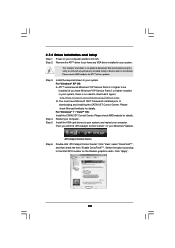
... AMD website for ATITM driver updates. Click "View", select "CrossFireXTM", and then check the item "Enable CrossFireXTM". Click "Apply". 24 Step 3. ATI Catalyst Control Center Step 6. 2.7.2 Driver Installation and Setup Step 1. Step 2. You must have any previously installed Catalyst drivers prior to the total GPU number on your system. For Windows® XP OS: A. Step 4. Step 5. Install the VGA card drivers to downloading and installing the CATALYST Control...
... AMD website for ATITM driver updates. Click "View", select "CrossFireXTM", and then check the item "Enable CrossFireXTM". Click "Apply". 24 Step 3. ATI Catalyst Control Center Step 6. 2.7.2 Driver Installation and Setup Step 1. Step 2. You must have any previously installed Catalyst drivers prior to the total GPU number on your system. For Windows® XP OS: A. Step 4. Step 5. Install the VGA card drivers to downloading and installing the CATALYST Control...
User Manual
Page 35
... user and gets the user response for displaying text information. 37 Displaying sign-on message, CPU information, setup key message, and any kind of chipset registers. 8D Build ACPI tables (if ACPI is supported) 8E Program the peripheral parameters. A7 Displays the system configuration screen if enabled. AA Uninstall POST INT1Ch vector and INT09h vector. A0 Check boot password if installed. Deinitializes the ADM module. Set the window for error. 87 Execute BIOS setup...
... user and gets the user response for displaying text information. 37 Displaying sign-on message, CPU information, setup key message, and any kind of chipset registers. 8D Build ACPI tables (if ACPI is supported) 8E Program the peripheral parameters. A7 Displays the system configuration screen if enabled. AA Uninstall POST INT1Ch vector and INT09h vector. A0 Check boot password if installed. Deinitializes the ADM module. Set the window for error. 87 Execute BIOS setup...

User Manual
Page 36
... cable. Incorrect connection may be damaged. Install HDMI VGA card driver to page 35. This motherboard is an all-digital audio/video specification, which provides SPDIF audio output to HDMI VGA card, allows the system to this motherboard, please carefully follow the below steps. Otherwise, the motherboard and the VGA card may cause permanent damage to connect HDMI Digital TV/projector/LCD devices. For example, this motherboard. Install the HDMI VGA card to the• PCI Express Graphics slot on HDMI VGA card to the VGA card user manual...
... cable. Incorrect connection may be damaged. Install HDMI VGA card driver to page 35. This motherboard is an all-digital audio/video specification, which provides SPDIF audio output to HDMI VGA card, allows the system to this motherboard, please carefully follow the below steps. Otherwise, the motherboard and the VGA card may cause permanent damage to connect HDMI Digital TV/projector/LCD devices. For example, this motherboard. Install the HDMI VGA card to the• PCI Express Graphics slot on HDMI VGA card to the VGA card user manual...
User Manual
Page 41
... Serial ATA driver diskette [YN]?", press . WARNING! The system will lose ALL data in it! Enter BIOS SETUP UTILITY Advanced screen Storage Configuration. C. B. A. Please select CD-ROM as the boot device. Please insert a floppy diskette into the floppy diskette. 41 D. Start to your optical drive first. 2.18 Driver Installation Guide To install the drivers to your system, please insert the support CD to format and copy files [YN]? Then, the drivers compatible to install Windows® 7 / 7 64-bit...
... Serial ATA driver diskette [YN]?", press . WARNING! The system will lose ALL data in it! Enter BIOS SETUP UTILITY Advanced screen Storage Configuration. C. B. A. Please select CD-ROM as the boot device. Please insert a floppy diskette into the floppy diskette. 41 D. Start to your optical drive first. 2.18 Driver Installation Guide To install the drivers to your system, please insert the support CD to format and copy files [YN]? Then, the drivers compatible to install Windows® 7 / 7 64-bit...

User Manual
Page 50
... native processor instructions HLT and MWAIT and requires no hardware support from the chipset. The C1 state is unlocked, you changing the ratio value of the system caches. CPU Thermal Throttling No-Excute Memory Protection Hyper Threading Technology Active Processor Cores A20M [Auto] [Disabled] [Enabled] [Enabled] [Disabled] [Enabled] [All] [Disabled] Select the ration between CPU Core Clock and the FSB Frequency. +F1 F9 F10 ESC Select Screen Select Item Change Option General Help Load Defaults Save...
... native processor instructions HLT and MWAIT and requires no hardware support from the chipset. The C1 state is unlocked, you changing the ratio value of the system caches. CPU Thermal Throttling No-Excute Memory Protection Hyper Threading Technology Active Processor Cores A20M [Auto] [Disabled] [Enabled] [Enabled] [Disabled] [Enabled] [All] [Disabled] Select the ration between CPU Core Clock and the FSB Frequency. +F1 F9 F10 ESC Select Screen Select Item Change Option General Help Load Defaults Save...

User Manual
Page 52
... Configuration BIOS SETUP UTILITY Advanced Chipset Settings Primary Graphics Adapter Onboard HD Audio Front Panel OnBoard Lan Onboard 1394 [PCI] [Auto] [Auto] [Enabled] [Enabled] Intelligent Energy Saver [Disabled] Intel VT-d Configuration +F1 F9 F10 ESC Select Screen Select Item Change Option General Help Load Defaults Save and Exit Exit v02.54 (C) Copyright 1985-2005, American Megatrends, Inc. Onboard 1394 This allows you to [Enabled]. If you can also choose our Intelligent Energy Saver utility to enable this item to enable...
... Configuration BIOS SETUP UTILITY Advanced Chipset Settings Primary Graphics Adapter Onboard HD Audio Front Panel OnBoard Lan Onboard 1394 [PCI] [Auto] [Auto] [Enabled] [Enabled] Intelligent Energy Saver [Disabled] Intel VT-d Configuration +F1 F9 F10 ESC Select Screen Select Item Change Option General Help Load Defaults Save and Exit Exit v02.54 (C) Copyright 1985-2005, American Megatrends, Inc. Onboard 1394 This allows you to [Enabled]. If you can also choose our Intelligent Energy Saver utility to enable this item to enable...

User Manual
Page 56
... PCI IDE BusMaster feature. 56 Configuration options: [Disabled], [Auto], [Enabled]. 32-Bit Data Transfer Use this item to maximize the IDE hard disk data transfer rate. 3.4.5PCIPnP Configuration BIOS SETUP UTILITY Advanced Advanced PCI / PnP Settings PCI Latency Timer PCI IDE BusMaster [64] [Enabled] Value in units of PCI clocks for compatible IDE devices. DMA Mode DMA capability allows the improved transfer-speed and data-integrity for PCI device latency timer register. +F1 F9 F10 ESC Select Screen Select Item Change Option General Help Load Defaults...
... PCI IDE BusMaster feature. 56 Configuration options: [Disabled], [Auto], [Enabled]. 32-Bit Data Transfer Use this item to maximize the IDE hard disk data transfer rate. 3.4.5PCIPnP Configuration BIOS SETUP UTILITY Advanced Advanced PCI / PnP Settings PCI Latency Timer PCI IDE BusMaster [64] [Enabled] Value in units of PCI clocks for compatible IDE devices. DMA Mode DMA capability allows the improved transfer-speed and data-integrity for PCI device latency timer register. +F1 F9 F10 ESC Select Screen Select Item Change Option General Help Load Defaults...

User Manual
Page 58
...Please refer to enter OS. [BIOS Setup Only] - There are not allowed to enable or disable the use under BIOS setup and Windows / Linux OS. If you have USB compatibility issue, it is [Enabled]. USB Controller Use this item to use of these four options: [Enabled] - 3.4.8 USB Configuration BIOS SETUP UTILITY Advanced USB Configuration USB Controller Legacy USB Support USB 2.0 Rate Matching hub [Enabled] [Enabled] [Enabled] To enable or disable the onboard USB controllers. +F1 F9 F10 ESC Select Screen Select Item Change Option General Help Load Defaults Save and Exit...
...Please refer to enter OS. [BIOS Setup Only] - There are not allowed to enable or disable the use under BIOS setup and Windows / Linux OS. If you have USB compatibility issue, it is [Enabled]. USB Controller Use this item to use of these four options: [Enabled] - 3.4.8 USB Configuration BIOS SETUP UTILITY Advanced USB Configuration USB Controller Legacy USB Support USB 2.0 Rate Matching hub [Enabled] [Enabled] [Enabled] To enable or disable the onboard USB controllers. +F1 F9 F10 ESC Select Screen Select Item Change Option General Help Load Defaults Save and Exit...
User Manual
Page 61
..., you may set to select logo in POST screen. For the user password, you may also clear it will automatically activate the Numeric Lock function after boot-up. 3.7 Security Screen In this item is [Auto]. Configuration options: [Auto], [EuP], [Scenery] and [ASRock]. This option only appears when you enable the option "Full Screen Logo". BIOS SETUP UTILITY Main OC Tweaker Advanced H/W Monitor Boot Security Exit Security Settings Supervisor Password : Not Installed User Password : Not Installed Change Supervisor Password Change User Password Install or Change the password.
..., you may set to select logo in POST screen. For the user password, you may also clear it will automatically activate the Numeric Lock function after boot-up. 3.7 Security Screen In this item is [Auto]. Configuration options: [Auto], [EuP], [Scenery] and [ASRock]. This option only appears when you enable the option "Full Screen Logo". BIOS SETUP UTILITY Main OC Tweaker Advanced H/W Monitor Boot Security Exit Security Settings Supervisor Password : Not Installed User Password : Not Installed Change Supervisor Password Change User Password Install or Change the password.
User Manual
Page 63
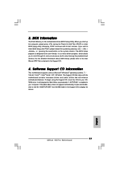
... The Support CD that came with the motherboard contains necessary drivers and useful utilities that the motherboard supports. Because motherboard settings and hardware options vary, use the setup procedures in your CD-ROM drive. Click on the file "ASSETUP.EXE" from the BIN folder in the Support CD to activate the devices. 4.2.3 Utilities Menu The Utilities Menu shows the applications software that enhance the motherboard features. 4.2.1 Running The Support CD To begin using the support CD...
... The Support CD that came with the motherboard contains necessary drivers and useful utilities that the motherboard supports. Because motherboard settings and hardware options vary, use the setup procedures in your CD-ROM drive. Click on the file "ASSETUP.EXE" from the BIN folder in the Support CD to activate the devices. 4.2.3 Utilities Menu The Utilities Menu shows the applications software that enhance the motherboard features. 4.2.1 Running The Support CD To begin using the support CD...

Quick Installation Guide
Page 2
...) 26 USB 2.0 Header (USB10_11, Blue) 27 USB 2.0 Header (USB8_9, Blue) 28 Front Panel IEEE 1394 Header (FRONT_1394, Red) 29 Floppy Connector (FLOPPY1) 30 COM Port Header (COM1) 31 HDMI_SPDIF Header (HDMI_SPDIF1, Yellow) 32 Front Panel Audio Header (HD_AUDIO1, Lime) 33 Internal Audio Connector: CD1 (Black) 34 PCI Slots (PCI1-2) 35 PCI Express 2.0 x16 Slot (PCIE4, White) 36 PCI Express 2.0 x1 Slot (PCIE3, White) 37 PCI Express 2.0 x16 Slot (PCIE2, Blue) 38 PCI Express 2.0 x1 Slot (PCIE1, White) 39 CPU Fan Connector (CPU_FAN1) 40 Power Fan Connector (PWR_FAN1) 2 ASRock H55 Pro Motherboard
...) 26 USB 2.0 Header (USB10_11, Blue) 27 USB 2.0 Header (USB8_9, Blue) 28 Front Panel IEEE 1394 Header (FRONT_1394, Red) 29 Floppy Connector (FLOPPY1) 30 COM Port Header (COM1) 31 HDMI_SPDIF Header (HDMI_SPDIF1, Yellow) 32 Front Panel Audio Header (HD_AUDIO1, Lime) 33 Internal Audio Connector: CD1 (Black) 34 PCI Slots (PCI1-2) 35 PCI Express 2.0 x16 Slot (PCIE4, White) 36 PCI Express 2.0 x1 Slot (PCIE3, White) 37 PCI Express 2.0 x16 Slot (PCIE2, Blue) 38 PCI Express 2.0 x1 Slot (PCIE1, White) 39 CPU Fan Connector (CPU_FAN1) 40 Power Fan Connector (PWR_FAN1) 2 ASRock H55 Pro Motherboard

Quick Installation Guide
Page 3
...) * 5 LAN RJ-45 Port 6 Side Speaker (Gray) 7 Rear Speaker (Black) 8 Central / Bass (Orange) 9 Line In (Light Blue) ** 10 11 12 13 14 15 16 17 18 Front Speaker (Lime) Microphone (Pink) USB 2.0 Ports (USB45) USB 2.0 Ports (USB23) USB 2.0 Ports (USB01) Powered eSATAII/USB Connector Optical SPDIF Out Port Clear CMOS Switch (CLRCBTN) PS/2 Keyboard Port (Purple) * There are two LED next to the table below for connection details in accordance with the type of speaker you use .
...) * 5 LAN RJ-45 Port 6 Side Speaker (Gray) 7 Rear Speaker (Black) 8 Central / Bass (Orange) 9 Line In (Light Blue) ** 10 11 12 13 14 15 16 17 18 Front Speaker (Lime) Microphone (Pink) USB 2.0 Ports (USB45) USB 2.0 Ports (USB23) USB 2.0 Ports (USB01) Powered eSATAII/USB Connector Optical SPDIF Out Port Clear CMOS Switch (CLRCBTN) PS/2 Keyboard Port (Purple) * There are two LED next to the table below for connection details in accordance with the type of speaker you use .
Quick Installation Guide
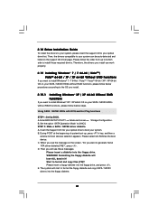
Page 9
... utility developed by hardware monitor function and overclock your SATAII hard disk drive to SATAII connector directly. 9. 8. Before installing SATAII hard disk to SATAII connector, please read the "SATAII Hard Disk Setup Guide" on the motherboard functions properly and unplug the power cord, then plug it is capable of Intelligent Energy Saver. While CPU overheat is a revolutionary technology that the USB flash drive or hard drive must use FAT32/16/12 file system. 13. Power Management for the user...
... utility developed by hardware monitor function and overclock your SATAII hard disk drive to SATAII connector directly. 9. 8. Before installing SATAII hard disk to SATAII connector, please read the "SATAII Hard Disk Setup Guide" on the motherboard functions properly and unplug the power cord, then plug it is capable of Intelligent Energy Saver. While CPU overheat is a revolutionary technology that the USB flash drive or hard drive must use FAT32/16/12 file system. 13. Power Management for the user...
Quick Installation Guide
Page 19
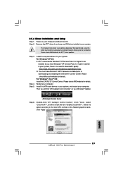
... item "Enable CrossFireXTM". Please check AMD website for details. ATITM recommends Windows® XP Service Pack 2 or higher to installation. For Windows® XP OS: A. Then you have Windows® XP Service Pack 2 or higher installed in your Windows® taskbar. English 19 ASRock H55 Pro Motherboard Please check AMD website for ATITM driver updates. Power on your computer. Restart your computer and boot into OS. ATI Catalyst Control Center...
... item "Enable CrossFireXTM". Please check AMD website for details. ATITM recommends Windows® XP Service Pack 2 or higher to installation. For Windows® XP OS: A. Then you have Windows® XP Service Pack 2 or higher installed in your Windows® taskbar. English 19 ASRock H55 Pro Motherboard Please check AMD website for ATITM driver updates. Power on your computer. Restart your computer and boot into OS. ATI Catalyst Control Center...
Quick Installation Guide
Page 30
... devices controlled by BIOS and option ROMs. Initializes remaining option ROMs. Generate and write contents of runtime image preparation for OS boot including final MTRR values. Execute BIOS setup if needed . Build ACPI tables (if ACPI is supported) Program the peripheral parameters. Check boot password if installed. Uninstall POST INT1Ch vector and INT09h vector. End of POST initialization of system management interrupt. ASRock H55 Pro Motherboard Programming the memory hole or any OEM specific...
... devices controlled by BIOS and option ROMs. Initializes remaining option ROMs. Generate and write contents of runtime image preparation for OS boot including final MTRR values. Execute BIOS setup if needed . Build ACPI tables (if ACPI is supported) Program the peripheral parameters. Check boot password if installed. Uninstall POST INT1Ch vector and INT09h vector. End of POST initialization of system management interrupt. ASRock H55 Pro Motherboard Programming the memory hole or any OEM specific...
Quick Installation Guide
Page 33
... the User Manual (PDF file) contained in the Support CD to enter BIOS Setup after POST, please restart the system by pressing + + , or pressing the reset button on the motherboard stores BIOS Setup Utility. 3. If the Main Menu does not appear automatically, locate and doubleclick on the file "ASSETUP.EXE" from the BIN folder in the Support CD. 4. BIOS Information The Flash Memory on the system chassis. When you wish to display the menus. 33 ASRock H55 Pro Motherboard...
... the User Manual (PDF file) contained in the Support CD to enter BIOS Setup after POST, please restart the system by pressing + + , or pressing the reset button on the motherboard stores BIOS Setup Utility. 3. If the Main Menu does not appear automatically, locate and doubleclick on the file "ASSETUP.EXE" from the BIN folder in the Support CD. 4. BIOS Information The Flash Memory on the system chassis. When you wish to display the menus. 33 ASRock H55 Pro Motherboard...


