
User Manual
Page 4
... 1 1.2 Specifications 2 1.3 Motherboard Layout 6 1.4 I/O Panel 8 Chapter 2 Installation 10 2.1 Installing the CPU 11 2.2 Installing the CPU Fan and Heatsink 14 2.3 Installing Memory Modules (DIMM) 15 2.4 Expansion Slots (PCI Express Slots) 17 2.5 Onboard Headers and Connectors 18 Chapter 3 Software and Utilities Operation 22 3.1 Installing Drivers 22 3.2 ASRock Live Update & APP Shop 23 3.2.1 UI Overview 23 3.2.2 Apps 24 3.2.3 BIOS & Drivers 27 3.2.4 Setting 28 3.3 Enabling USB Ports for Windows® 7 Installation 29 Chapter 4 UEFI SETUP UTILITY 32...
... 1 1.2 Specifications 2 1.3 Motherboard Layout 6 1.4 I/O Panel 8 Chapter 2 Installation 10 2.1 Installing the CPU 11 2.2 Installing the CPU Fan and Heatsink 14 2.3 Installing Memory Modules (DIMM) 15 2.4 Expansion Slots (PCI Express Slots) 17 2.5 Onboard Headers and Connectors 18 Chapter 3 Software and Utilities Operation 22 3.1 Installing Drivers 22 3.2 ASRock Live Update & APP Shop 23 3.2.1 UI Overview 23 3.2.2 Apps 24 3.2.3 BIOS & Drivers 27 3.2.4 Setting 28 3.3 Enabling USB Ports for Windows® 7 Installation 29 Chapter 4 UEFI SETUP UTILITY 32...
User Manual
Page 6
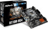
... • ASRock H110M-HG4 Motherboard (Micro ATX Form Factor) • ASRock H110M-HG4 Quick Installation Guide • ASRock H110M-HG4 Support CD • 2 x Serial ATA (SATA) Data Cables (Optional) • 1 x I/O Panel Shield 1 English Chapter 4 contains the configuration guide of the software and utilities. If you are using. Because the motherboard specifications and the BIOS software might be updated, the content of this documentation will be subject to quality and endurance. H110M-HG4 Chapter 1 Introduction Thank you for specific information about the model you...
... • ASRock H110M-HG4 Motherboard (Micro ATX Form Factor) • ASRock H110M-HG4 Quick Installation Guide • ASRock H110M-HG4 Support CD • 2 x Serial ATA (SATA) Data Cables (Optional) • 1 x I/O Panel Shield 1 English Chapter 4 contains the configuration guide of the software and utilities. If you are using. Because the motherboard specifications and the BIOS software might be updated, the content of this documentation will be subject to quality and endurance. H110M-HG4 Chapter 1 Introduction Thank you for specific information about the model you...

User Manual
Page 8
... panel audio module and enable the multi-channel audio feature through the audio driver. • Supports Surge Protection (ASRock Full Spike Protection) • ELNA Audio Caps LAN • PCIE x1 Gigabit LAN 10/100/1000 Mb/s • Realtek RTL8111GR/RTL8111C • Supports Wake-On-LAN • Supports Lightning/ESD Protection (ASRock Full Spike Protection) • Supports LAN Cable Detection • Supports PXE Rear Panel • 1 x PS/2 Mouse/Keyboard Port I/O • 1 x D-Sub Port • 1 x HDMI Port • 4 x USB 2.0 Ports (Supports ESD Protection (ASRock...
... panel audio module and enable the multi-channel audio feature through the audio driver. • Supports Surge Protection (ASRock Full Spike Protection) • ELNA Audio Caps LAN • PCIE x1 Gigabit LAN 10/100/1000 Mb/s • Realtek RTL8111GR/RTL8111C • Supports Wake-On-LAN • Supports Lightning/ESD Protection (ASRock Full Spike Protection) • Supports LAN Cable Detection • Supports PXE Rear Panel • 1 x PS/2 Mouse/Keyboard Port I/O • 1 x D-Sub Port • 1 x HDMI Port • 4 x USB 2.0 Ports (Supports ESD Protection (ASRock...

User Manual
Page 9
... pin ATX Power Connector • 1 x 8 pin 12V Power Connector • 1 x Front Panel Audio Connector • 2 x USB 2.0 Headers (Support 4 USB 2.0 ports) (Supports ESD Protection (ASRock Full Spike Protection)) • 1 x USB 3.0 Header (Supports 2 USB 3.0 ports) (Supports ESD Protection (ASRock Full Spike Protection)) * USB_11_12 is shared with multilingual GUI support • ACPI 5.0 Compliant wake up events • SMBIOS 2.7 Support • CPU, DRAM, PCH 1.0V, VCCIO Voltage Multi-adjustment Hardware Monitor • CPU/Chassis temperature sensing • CPU/Chassis Fan Tachometer...
... pin ATX Power Connector • 1 x 8 pin 12V Power Connector • 1 x Front Panel Audio Connector • 2 x USB 2.0 Headers (Support 4 USB 2.0 ports) (Supports ESD Protection (ASRock Full Spike Protection)) • 1 x USB 3.0 Header (Supports 2 USB 3.0 ports) (Supports ESD Protection (ASRock Full Spike Protection)) * USB_11_12 is shared with multilingual GUI support • ACPI 5.0 Compliant wake up events • SMBIOS 2.7 Support • CPU, DRAM, PCH 1.0V, VCCIO Voltage Multi-adjustment Hardware Monitor • CPU/Chassis temperature sensing • CPU/Chassis Fan Tachometer...

User Manual
Page 12
... 2 CPU Fan Connector (CPU_FAN1) 3 2 x 288-pin DDR4 DIMM Slots (DDR4_A1, DDR4_B1) 4 ATX Power Connector (ATXPWR1) 5 USB 3.0 Header (USB_11_12) 6 USB 2.0 Header (USB_9_10) 7 Chassis Fan Connector (CHA_FAN2) 8 SATA3 Connector (SATA3_0) 9 SATA3 Connector (SATA3_1) 10 SATA3 Connector (SATA3_2) 11 SATA3 Connector (SATA3_3) 12 System Panel Header (PANEL1) 13 TPM Header (TPMS1) 14 Chassis Intrusion and Speaker Header (SPK_CI1) 15 USB 2.0 Header (USB_7_8) 16 Print Port Header (LPT1) 17 COM Port Header (COM1) 18 Front Panel Audio Header (HD_AUDIO1) 19 Chassis Fan Connector (CHA_FAN1) H110M-HG4 English...
... 2 CPU Fan Connector (CPU_FAN1) 3 2 x 288-pin DDR4 DIMM Slots (DDR4_A1, DDR4_B1) 4 ATX Power Connector (ATXPWR1) 5 USB 3.0 Header (USB_11_12) 6 USB 2.0 Header (USB_9_10) 7 Chassis Fan Connector (CHA_FAN2) 8 SATA3 Connector (SATA3_0) 9 SATA3 Connector (SATA3_1) 10 SATA3 Connector (SATA3_2) 11 SATA3 Connector (SATA3_3) 12 System Panel Header (PANEL1) 13 TPM Header (TPMS1) 14 Chassis Intrusion and Speaker Header (SPK_CI1) 15 USB 2.0 Header (USB_7_8) 16 Print Port Header (LPT1) 17 COM Port Header (COM1) 18 Front Panel Audio Header (HD_AUDIO1) 19 Chassis Fan Connector (CHA_FAN1) H110M-HG4 English...

User Manual
Page 22
... slot) is used for PCI Express x1 lane width cards. Before installing an expansion card, please make necessary hardware settings for PCI Express x1 lane width cards. 17 English PCIE3 (PCIe 2.0 x1 slot) is unplugged. Please read the documentation of the expansion card and make sure that the power supply is switched off or the power cord is used for the card before you start the installation. H110M-HG4 2.4 Expansion Slots (PCI Express Slots) There are 3 PCI Express slots on the motherboard...
... slot) is used for PCI Express x1 lane width cards. Before installing an expansion card, please make necessary hardware settings for PCI Express x1 lane width cards. 17 English PCIE3 (PCIe 2.0 x1 slot) is unplugged. Please read the documentation of the expansion card and make sure that the power supply is switched off or the power cord is used for the card before you start the installation. H110M-HG4 2.4 Expansion Slots (PCI Express Slots) There are 3 PCI Express slots on the motherboard...

User Manual
Page 25
... connect fan cables to the fan connector and match the black wire to Pin 1-3. If you plan to connect a 3-Pin CPU fan, please connect it to the ground pin. B. C. MIC_RET and OUT_RET are for the AC'97 audio panel. CPU Fan Connector (4-pin CPU_FAN1) (see p.6, No. 18) GND PRESENCE# MIC_RET OUT_RET 1 OUT2_L J_SENSE OUT2_R MIC2_R MIC2_L This header is for connecting audio devices to the front panel audio header by the steps below: A. If you use a 20-pin ATX power supply...
... connect fan cables to the fan connector and match the black wire to Pin 1-3. If you plan to connect a 3-Pin CPU fan, please connect it to the ground pin. B. C. MIC_RET and OUT_RET are for the AC'97 audio panel. CPU Fan Connector (4-pin CPU_FAN1) (see p.6, No. 18) GND PRESENCE# MIC_RET OUT_RET 1 OUT2_L J_SENSE OUT2_R MIC2_R MIC2_L This header is for connecting audio devices to the front panel audio header by the steps below: A. If you use a 20-pin ATX power supply...
User Manual
Page 27
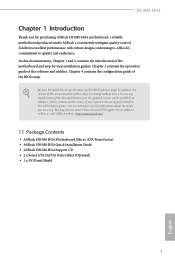
... to your CD-ROM drive. To improve Windows 7 compatibility, please download and install the following hot fix provided by Microsoft. Chapter 3 Software and Utilities Operation 3.1 Installing Drivers The Support CD that comes with the motherboard contains necessary drivers and useful utilities that the motherboard supports. Running The Support CD To begin using the support CD, insert the CD into your system will be auto-detected and listed on a specific item then follow the...
... to your CD-ROM drive. To improve Windows 7 compatibility, please download and install the following hot fix provided by Microsoft. Chapter 3 Software and Utilities Operation 3.1 Installing Drivers The Support CD that comes with the motherboard contains necessary drivers and useful utilities that the motherboard supports. Running The Support CD To begin using the support CD, insert the CD into your system will be auto-detected and listed on a specific item then follow the...
User Manual
Page 34
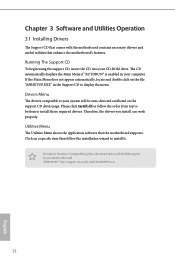
... optical disc drive, PS/2 ports and PS/2 Keyboard or mouse on your computer, please enable the "PS/2 Simulator" option in the Windows 7 inbox drivers, users may find another computer and follow the instructions below and go ahead to create a new ISO file with the Intel® USB 3.0 eXtensible Host Controller (xHCI) drivers packed into the ISO file. Please set PS/S Simulator back to install Windows® 7 OS...
... optical disc drive, PS/2 ports and PS/2 Keyboard or mouse on your computer, please enable the "PS/2 Simulator" option in the Windows 7 inbox drivers, users may find another computer and follow the instructions below and go ahead to create a new ISO file with the Intel® USB 3.0 eXtensible Host Controller (xHCI) drivers packed into the ISO file. Please set PS/S Simulator back to install Windows® 7 OS...
User Manual
Page 35
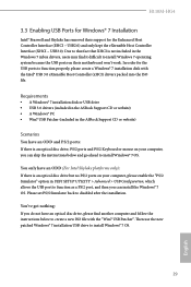
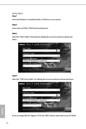
Step 4 Select the "USB Driver Folder" by clicking the red circle as shown as the picture below . Step 2 Extract the tool (Win7 USB Patcher) and launch it. If you are using ASRock's Support CD for the USB 3.0 driver, please select your system. Step 3 Select the "Win7 Folder" from Step1 by clicking the red circle as shown as the picture below . Instructions Step 1 Insert the Windows® 7 installation disk or USB drive to your CD-ROM. 30 English
Step 4 Select the "USB Driver Folder" by clicking the red circle as shown as the picture below . Step 2 Extract the tool (Win7 USB Patcher) and launch it. If you are using ASRock's Support CD for the USB 3.0 driver, please select your system. Step 3 Select the "Win7 Folder" from Step1 by clicking the red circle as shown as the picture below . Instructions Step 1 Insert the Windows® 7 installation disk or USB drive to your CD-ROM. 30 English

User Manual
Page 53
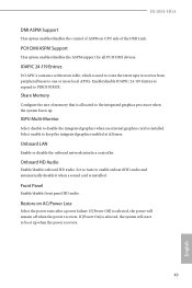
... reliability, and providing additional levels of manageability, security, isolation, and I/O performance. 4.6.2 Chipset Configuration Primary Graphics Adapter Select a primary VGA. PCH PCIE ASPM Support This option enables/disables the ASPM support for all PCH PCIE devices. 48 English Dynamic assignment would adjust TOLUD automatically based on largest MMIO length of TOLUD. VT-d Intel® Virtualization Technology for PCIE1. Top Of Lower Usable Dram Maximum Value of installed graphic controller.
... reliability, and providing additional levels of manageability, security, isolation, and I/O performance. 4.6.2 Chipset Configuration Primary Graphics Adapter Select a primary VGA. PCH PCIE ASPM Support This option enables/disables the ASPM support for all PCH PCIE devices. 48 English Dynamic assignment would adjust TOLUD automatically based on largest MMIO length of TOLUD. VT-d Intel® Virtualization Technology for PCIE1. Top Of Lower Usable Dram Maximum Value of installed graphic controller.
User Manual
Page 54
.... IGPU Multi-Monitor Select disable to keep the integrated graphics enabled at all PCH DMI devices. Onboard HD Audio Enable/disable onboard HD audio. Select enable to disable the integrated graphics when an external graphics card is installed. PCH DMI ASPM Support This option enables/disables the ASPM support for all times. H110M-HG4 DMI ASPM Support This option enables/disables the control of ASPM on AC/Power Loss Select the power state after a power failure. Front Panel Enable/disable front panel HD audio. Share Memory Configure the size of the...
.... IGPU Multi-Monitor Select disable to keep the integrated graphics enabled at all PCH DMI devices. Onboard HD Audio Enable/disable onboard HD audio. Select enable to disable the integrated graphics when an external graphics card is installed. PCH DMI ASPM Support This option enables/disables the ASPM support for all times. H110M-HG4 DMI ASPM Support This option enables/disables the control of ASPM on AC/Power Loss Select the power state after a power failure. Front Panel Enable/disable front panel HD audio. Share Memory Configure the size of the...
User Manual
Page 61
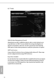
... setup network configuration before using UEFI Tech Service. 4.7 Tools OMG (Online Management Guard) Administrators are able to establish an internet curfew or restrict internet access at specified times via an USB storage device, then downloads and installs the other users. You may schedule the starting and ending hours of internet access granted to your PC. UEFI Tech Service Contact ASRock Tech Service if you are required. Easy Driver Installer For users that installs...
... setup network configuration before using UEFI Tech Service. 4.7 Tools OMG (Online Management Guard) Administrators are able to establish an internet curfew or restrict internet access at specified times via an USB storage device, then downloads and installs the other users. You may schedule the starting and ending hours of internet access granted to your PC. UEFI Tech Service Contact ASRock Tech Service if you are required. Easy Driver Installer For users that installs...
User Manual
Page 62
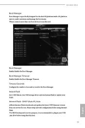
... Flash - Please setup network configuration before using Internet Flash. *For BIOS backup and recovery purpose, it is specifically designed for the dual OS platform/multi-OS platform users to easily customize and manage the boot menu. *Please connect more than one boot devices to use this function. 57 English Boot Manager Enable/disable the Boot Manager. Instant Flash Save UEFI files in your UEFI. Boot Manager Timeout Enable/disable the Boot Manager Timeout. DHCP (Auto IP), Auto ASRock Internet Flash downloads and updates the latest UEFI firmware version...
... Flash - Please setup network configuration before using Internet Flash. *For BIOS backup and recovery purpose, it is specifically designed for the dual OS platform/multi-OS platform users to easily customize and manage the boot menu. *Please connect more than one boot devices to use this function. 57 English Boot Manager Enable/disable the Boot Manager. Instant Flash Save UEFI files in your UEFI. Boot Manager Timeout Enable/disable the Boot Manager Timeout. DHCP (Auto IP), Auto ASRock Internet Flash downloads and updates the latest UEFI firmware version...

User Manual
Page 63
UEFI Download Server Select a server to configure internet connection settings for Internet Flash. Internet Setting Enable or disable sound effects in the setup utility. Network Configuration Use this to download the UEFI firmware. 58 English
UEFI Download Server Select a server to configure internet connection settings for Internet Flash. Internet Setting Enable or disable sound effects in the setup utility. Network Configuration Use this to download the UEFI firmware. 58 English

User Manual
Page 66
User Password Set or change the password for Windows 8.1 Secure Boot. Secure Boot Use this item to change the settings in ME. H110M-HG4 4.9 Security Screen In this section you may also clear the user password. Supervisor Password Set or change the settings in the UEFI Setup Utility. Only the administrator has authority to enable or disable support for the user account. Intel(R) Platform Trust Technology Enable/disable Intel PTT in the UEFI Setup Utility. You may set or change the supervisor/user password for the administrator account. Users are...
User Password Set or change the password for Windows 8.1 Secure Boot. Secure Boot Use this item to change the settings in ME. H110M-HG4 4.9 Security Screen In this section you may also clear the user password. Supervisor Password Set or change the settings in the UEFI Setup Utility. Only the administrator has authority to enable or disable support for the user account. Intel(R) Platform Trust Technology Enable/disable Intel PTT in the UEFI Setup Utility. You may set or change the supervisor/user password for the administrator account. Users are...

Quick Installation Guide
Page 4
... 12V Power Connector (ATX12V1) 2 CPU Fan Connector (CPU_FAN1) 3 2 x 288-pin DDR4 DIMM Slots (DDR4_A1, DDR4_B1) 4 ATX Power Connector (ATXPWR1) 5 USB 3.0 Header (USB_11_12) 6 USB 2.0 Header (USB_9_10) 7 Chassis Fan Connector (CHA_FAN2) 8 SATA3 Connector (SATA3_0) 9 SATA3 Connector (SATA3_1) 10 SATA3 Connector (SATA3_2) 11 SATA3 Connector (SATA3_3) 12 System Panel Header (PANEL1) 13 TPM Header (TPMS1) 14 Chassis Intrusion and Speaker Header (SPK_CI1) 15 USB 2.0 Header (USB_7_8) 16 Print Port Header (LPT1) 17 COM Port Header (COM1) 18 Front Panel Audio Header (HD_AUDIO1) 19 Chassis Fan Connector...
... 12V Power Connector (ATX12V1) 2 CPU Fan Connector (CPU_FAN1) 3 2 x 288-pin DDR4 DIMM Slots (DDR4_A1, DDR4_B1) 4 ATX Power Connector (ATXPWR1) 5 USB 3.0 Header (USB_11_12) 6 USB 2.0 Header (USB_9_10) 7 Chassis Fan Connector (CHA_FAN2) 8 SATA3 Connector (SATA3_0) 9 SATA3 Connector (SATA3_1) 10 SATA3 Connector (SATA3_2) 11 SATA3 Connector (SATA3_3) 12 System Panel Header (PANEL1) 13 TPM Header (TPMS1) 14 Chassis Intrusion and Speaker Header (SPK_CI1) 15 USB 2.0 Header (USB_7_8) 16 Print Port Header (LPT1) 17 COM Port Header (COM1) 18 Front Panel Audio Header (HD_AUDIO1) 19 Chassis Fan Connector...

Quick Installation Guide
Page 10
... pin ATX Power Connector • 1 x 8 pin 12V Power Connector • 1 x Front Panel Audio Connector • 2 x USB 2.0 Headers (Support 4 USB 2.0 ports) (Supports ESD Protection (ASRock Full Spike Protection)) • 1 x USB 3.0 Header (Supports 2 USB 3.0 ports) (Supports ESD Protection (ASRock Full Spike Protection)) * USB_11_12 is shared with multilingual GUI support • ACPI 5.0 Compliant wake up events • SMBIOS 2.7 Support • CPU, DRAM, PCH 1.0V, VCCIO Voltage Multi-adjustment Hardware Monitor • CPU/Chassis temperature sensing • CPU/Chassis Fan Tachometer...
... pin ATX Power Connector • 1 x 8 pin 12V Power Connector • 1 x Front Panel Audio Connector • 2 x USB 2.0 Headers (Support 4 USB 2.0 ports) (Supports ESD Protection (ASRock Full Spike Protection)) • 1 x USB 3.0 Header (Supports 2 USB 3.0 ports) (Supports ESD Protection (ASRock Full Spike Protection)) * USB_11_12 is shared with multilingual GUI support • ACPI 5.0 Compliant wake up events • SMBIOS 2.7 Support • CPU, DRAM, PCH 1.0V, VCCIO Voltage Multi-adjustment Hardware Monitor • CPU/Chassis temperature sensing • CPU/Chassis Fan Tachometer...

Quick Installation Guide
Page 56
... instructions below to function properly, please create a Windows® 7 installation disk with the "Win7 USB Patcher". Please set PS/S Simulator back to install Windows® 7 OS. 54 English Due to that fact that XHCI is an optical disc drive, PS/2 ports and PS/2 Keyboard or mouse on their support for the USB ports to create a new ISO file with the Intel® USB 3.0 eXtensible Host Controller (xHCI) drivers...
... instructions below to function properly, please create a Windows® 7 installation disk with the "Win7 USB Patcher". Please set PS/S Simulator back to install Windows® 7 OS. 54 English Due to that fact that XHCI is an optical disc drive, PS/2 ports and PS/2 Keyboard or mouse on their support for the USB ports to create a new ISO file with the Intel® USB 3.0 eXtensible Host Controller (xHCI) drivers...
Quick Installation Guide
Page 57
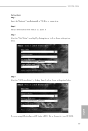
H110M-HG4 Instructions Step 1 Insert the Windows® 7 installation disk or USB drive to your CD-ROM. 55 English If you are using ASRock's Support CD for the USB 3.0 driver, please select your system. Step 4 Select the "USB Driver Folder" by clicking the red circle as shown as the picture below . Step 3 Select the "Win7 Folder" from Step1 by clicking the red circle as shown as the picture below . Step 2 Extract the tool (Win7 USB Patcher) and launch it.
H110M-HG4 Instructions Step 1 Insert the Windows® 7 installation disk or USB drive to your CD-ROM. 55 English If you are using ASRock's Support CD for the USB 3.0 driver, please select your system. Step 4 Select the "USB Driver Folder" by clicking the red circle as shown as the picture below . Step 3 Select the "Win7 Folder" from Step1 by clicking the red circle as shown as the picture below . Step 2 Extract the tool (Win7 USB Patcher) and launch it.


