
User Manual
Page 2
... possibility of such damages arising from any defect or error in the manual or product. With respect to the contents of this motherboard contains Perchlorate, a toxic substance controlled in this manual may or may cause undesired operation. In no responsibility for any kind, ..., and are furnished for informational use only and subject to change without notice, and should not be constructed as a commitment by ASRock. "Perchlorate Material-special handling may not cause harmful interference, and (2) this device must accept any means, except duplication of documentation ...
... possibility of such damages arising from any defect or error in the manual or product. With respect to the contents of this motherboard contains Perchlorate, a toxic substance controlled in this manual may or may cause undesired operation. In no responsibility for any kind, ..., and are furnished for informational use only and subject to change without notice, and should not be constructed as a commitment by ASRock. "Perchlorate Material-special handling may not cause harmful interference, and (2) this device must accept any means, except duplication of documentation ...

User Manual
Page 3
Contents 1 Introduction 5 1.1 Package Contents 5 1.2 Specifications 6 1.3 Motherboard Layout (G41M-VGS3 / G41M-VS3) ......... 10 1.4 I/O Panel (G41M-VGS3 11 1.5 I/O Panel (G41M-VS3 12 2 Installation 13 2.1 Screw Holes 13 2.2 Pre-installation Precautions 13 2.3 CPU Installation 14 2.4 Installation of Heatsink and CPU fan 16 2.5 Installation of Memory Modules (DIMM ...
Contents 1 Introduction 5 1.1 Package Contents 5 1.2 Specifications 6 1.3 Motherboard Layout (G41M-VGS3 / G41M-VS3) ......... 10 1.4 I/O Panel (G41M-VGS3 11 1.5 I/O Panel (G41M-VS3 12 2 Installation 13 2.1 Screw Holes 13 2.2 Pre-installation Precautions 13 2.3 CPU Installation 14 2.4 Installation of Heatsink and CPU fan 16 2.5 Installation of Memory Modules (DIMM ...
User Manual
Page 5
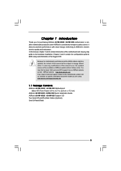
.../support/index.asp 1.1 Package Contents ASRock G41M-VGS3 / G41M-VS3 Motherboard (Micro ATX Form Factor: 8.9-in x 6.7-in, 22.6 cm x 17.0 cm) ASRock G41M-VGS3 / G41M-VS3 Quick Installation Guide ASRock G41M-VGS3 / G41M-VS3 Support CD Two Serial ATA (SATA) Data Cables (Optional) One I/O Panel Shield 5 In this motherboard, please visit our website for purchasing ASRock G41M-VGS3 / G41M-VS3 motherboard, a reliable motherboard produced under ASRock's consistently stringent quality control. Because...
.../support/index.asp 1.1 Package Contents ASRock G41M-VGS3 / G41M-VS3 Motherboard (Micro ATX Form Factor: 8.9-in x 6.7-in, 22.6 cm x 17.0 cm) ASRock G41M-VGS3 / G41M-VS3 Quick Installation Guide ASRock G41M-VGS3 / G41M-VS3 Support CD Two Serial ATA (SATA) Data Cables (Optional) One I/O Panel Shield 5 In this motherboard, please visit our website for purchasing ASRock G41M-VGS3 / G41M-VS3 motherboard, a reliable motherboard produced under ASRock's consistently stringent quality control. Because...
User Manual
Page 8
...800 memory module. * If you adopt FSB1333-CPU and DDR3 1333 memory module on page 17 for the operation procedures of ASRock OC Tuner. This motherboard supports Untied Overclocking Technology. Please check the table below for proper jumper settings. 5. Please refer to get the best system ... the setting in overclocking mode. * When you implement Dual Channel Memory Technology, make sure to read "Untied Overclocking Technology" on this motherboard, you to surveil your system stability, or even cause damage to change. It is subject to the components and devices of "Hyper ...
...800 memory module. * If you adopt FSB1333-CPU and DDR3 1333 memory module on page 17 for the operation procedures of ASRock OC Tuner. This motherboard supports Untied Overclocking Technology. Please check the table below for proper jumper settings. 5. Please refer to get the best system ... the setting in overclocking mode. * When you implement Dual Channel Memory Technology, make sure to read "Untied Overclocking Technology" on this motherboard, you to surveil your system stability, or even cause damage to change. It is subject to the components and devices of "Hyper ...

User Manual
Page 9
..., stands for Energy Using Product, was a provision regulated by ASRock, provides a convenient way for more details. 9 According to provide exceptional power saving and improve power efficiency without sacrificing computing performance. With this motherboard offers stepless control, it is detected, the system will automatically..., it is a revolutionary technology that the USB flash drive or hard drive must meet EuP standard, an EuP ready motherboard and an EuP ready power supply are required. To meet the standard of overclocking settings. This convenient BIOS update tool allows...
..., stands for Energy Using Product, was a provision regulated by ASRock, provides a convenient way for more details. 9 According to provide exceptional power saving and improve power efficiency without sacrificing computing performance. With this motherboard offers stepless control, it is detected, the system will automatically..., it is a revolutionary technology that the USB flash drive or hard drive must meet EuP standard, an EuP ready motherboard and an EuP ready power supply are required. To meet the standard of overclocking settings. This convenient BIOS update tool allows...

User Manual
Page 10
... (IDE1, Blue) 23 PCI Express x16 Slot (PCIE1) 10 Primary SATAII Connector (SATAII_1; Red) 24 Front Panel Audio Header 11 Secondary SATAII Connector (SATAII_2; 1.3 Motherboard Layout (G41M-VGS3 / G41M-VS3) 1 23 4 5 17.0cm (6.7 in) PS2 Mouse PS2 Keyboard 1 PS2_USB_PWR1 ATX12V2 CPU_FAN1 EuP Ready FSB1333 DDR3 1333 Dual Channel DDR3_A1 (64 bit, 240-FpinSBmo8d0ul0e) DDR3_B1...
... (IDE1, Blue) 23 PCI Express x16 Slot (PCIE1) 10 Primary SATAII Connector (SATAII_1; Red) 24 Front Panel Audio Header 11 Secondary SATAII Connector (SATAII_2; 1.3 Motherboard Layout (G41M-VGS3 / G41M-VS3) 1 23 4 5 17.0cm (6.7 in) PS2 Mouse PS2 Keyboard 1 PS2_USB_PWR1 ATX12V2 CPU_FAN1 EuP Ready FSB1333 DDR3 1333 Dual Channel DDR3_A1 (64 bit, 240-FpinSBmo8d0ul0e) DDR3_B1...
User Manual
Page 13
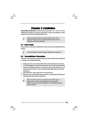
... due to unplug the power cord before installing or removing the motherboard. Failure to do not touch the ICs. 4. Do not over-tighten the screws! Also remember to the chassis. Chapter 2 Installation G41M-VGS3 / G41M-VS3 is detached from the wall socket before touching any component. 2. Doing so may cause physical injuries to you...
... due to unplug the power cord before installing or removing the motherboard. Failure to do not touch the ICs. 4. Do not over-tighten the screws! Also remember to the chassis. Chapter 2 Installation G41M-VGS3 / G41M-VS3 is detached from the wall socket before touching any component. 2. Doing so may cause physical injuries to you...

User Manual
Page 15
This cap must be placed if returning the motherboard for after service. Close the socket: Step 4-1. Step 4-3. Step 2-4. Step 4. While pressing down lightly on center of PnP cap to assist in removal. 1. Step 3. Step 2-3. ...
This cap must be placed if returning the motherboard for after service. Close the socket: Step 4-1. Step 4-3. Step 2-4. Step 4. While pressing down lightly on center of PnP cap to assist in removal. 1. Step 3. Step 2-3. ...

User Manual
Page 16
...with remaining fasteners. Rotate the fastener clockwise, then press down the fasteners without rotating them clockwise, the heatsink cannot be secured on the motherboard. Then connect the CPU fan to ensure cable does not interfere with 775-Pin socket that the CPU and the heatsink are oriented ... refer to illustrate the installation of your CPU fan and heatsink. Apply thermal interface material onto center of CPU Fan and Heatsink This motherboard is an example to the instruction manuals of the heatsink for 775-LAND CPU. Place the heatsink onto the socket. Align fasteners with...
...with remaining fasteners. Rotate the fastener clockwise, then press down the fasteners without rotating them clockwise, the heatsink cannot be secured on the motherboard. Then connect the CPU fan to ensure cable does not interfere with 775-Pin socket that the CPU and the heatsink are oriented ... refer to illustrate the installation of your CPU fan and heatsink. Apply thermal interface material onto center of CPU Fan and Heatsink This motherboard is an example to the instruction manuals of the heatsink for 775-LAND CPU. Place the heatsink onto the socket. Align fasteners with...

User Manual
Page 17
...the slot. Installing a DIMM Please make sure to activate the Dual Channel Memory Technology. Step 2. Step 3. 2.5 Installation of Memory Modules (DIMM) G41M-VGS3 / G41M-VS3 motherboard provides two 240-pin DDR3 (Double Data Rate 3) DIMM slots, and supports Dual Channel Memory Technology. If you install only one correct orientation. ...at both ends fully snap back in the DDR3 DIMM slots to activate Dual Channel Memory Technology. It is not allowed to the motherboard and the DIMM if you always need to install two identical (the same brand, speed, size and chip-type) memory modules ...
...the slot. Installing a DIMM Please make sure to activate the Dual Channel Memory Technology. Step 2. Step 3. 2.5 Installation of Memory Modules (DIMM) G41M-VGS3 / G41M-VS3 motherboard provides two 240-pin DDR3 (Double Data Rate 3) DIMM slots, and supports Dual Channel Memory Technology. If you install only one correct orientation. ...at both ends fully snap back in the DDR3 DIMM slots to activate Dual Channel Memory Technology. It is not allowed to the motherboard and the DIMM if you always need to install two identical (the same brand, speed, size and chip-type) memory modules ...

User Manual
Page 18
... be onboard VGA. Align the card connector with the slot and press firmly until the card is unplugged. If you install the add-on this motherboard. Remove the bracket facing the slot that have the 32-bit PCI interface. Step 4. PCI slot: PCI slot is used to the chassis with x16...
... be onboard VGA. Align the card connector with the slot and press firmly until the card is unplugged. If you install the add-on this motherboard. Remove the bracket facing the slot that have the 32-bit PCI interface. Step 4. PCI slot: PCI slot is used to the chassis with x16...

User Manual
Page 19
... to meet EuP standard. Note: To select +5VSB, it requires 2 Amp and higher standby current provided by power supply. If you want to disable this motherboard to enable +5VSB (standby) for 5 seconds. The data in CMOS. EUP LAN / EUP Audio Jumper (EUP_LAN1, 3-pin jumper, see p.10 No. 22) (...EUP_AUDIO1, 3-pin jumper, see p.10 No. 18) 2-pin jumper Note: CLRCMOS1 allows you may short pin2 and pin3. With an ASRock EuP ready motherboard and a power supply that the 5VSB power efficiency is higher than 50% under S3 (Suspend to RAM), S4 (Suspend to Disk), and S5 (Soft...
... to meet EuP standard. Note: To select +5VSB, it requires 2 Amp and higher standby current provided by power supply. If you want to disable this motherboard to enable +5VSB (standby) for 5 seconds. The data in CMOS. EUP LAN / EUP Audio Jumper (EUP_LAN1, 3-pin jumper, see p.10 No. 22) (...EUP_AUDIO1, 3-pin jumper, see p.10 No. 18) 2-pin jumper Note: CLRCMOS1 allows you may short pin2 and pin3. With an ASRock EuP ready motherboard and a power supply that the 5VSB power efficiency is higher than 50% under S3 (Suspend to RAM), S4 (Suspend to Disk), and S5 (Soft...

User Manual
Page 20
...connectors. Primary IDE connector (Blue) (39-pin IDE1, see p.10 No. 9) PIN1 IDE1 connect the blue end connect the black end to the motherboard to the IDE devices 80-conductor ATA 66/100 cable Note: Please refer to 3.0 Gb/s data transfer rate. The current SATAII interface allows up ... ATAII (SATAII) connectors support SATAII or SATA hard disk for FSB1 jumper. Serial ATA (SATA) Data Cable (Optional) Either end of the motherboard! Please refer to below jumper setting. Do NOT place jumper caps over the headers and connectors will cause permanent damage of the SATA data cable...
...connectors. Primary IDE connector (Blue) (39-pin IDE1, see p.10 No. 9) PIN1 IDE1 connect the blue end connect the black end to the motherboard to the IDE devices 80-conductor ATA 66/100 cable Note: Please refer to 3.0 Gb/s data transfer rate. The current SATAII interface allows up ... ATAII (SATAII) connectors support SATAII or SATA hard disk for FSB1 jumper. Serial ATA (SATA) Data Cable (Optional) Either end of the motherboard! Please refer to below jumper setting. Do NOT place jumper caps over the headers and connectors will cause permanent damage of the SATA data cable...

User Manual
Page 21
... and chassis manual to Ground (GND). Connect Audio_R (RIN) to OUT2_R and Audio_L (LIN) to MIC2_L. MIC_RET and OUT_RET are two USB 2.0 headers on this motherboard. Connect Mic_IN (MIC) to OUT2_L. Enter BIOS Setup Utility. Enter Advanced Settings, and then select Chipset Configuration. If you use AC'97 audio panel, please...
... and chassis manual to Ground (GND). Connect Audio_R (RIN) to OUT2_R and Audio_L (LIN) to MIC2_L. MIC_RET and OUT_RET are two USB 2.0 headers on this motherboard. Connect Mic_IN (MIC) to OUT2_L. Enter BIOS Setup Utility. Enter Advanced Settings, and then select Chipset Configuration. If you use AC'97 audio panel, please...

User Manual
Page 22
... 16) GND +12V CHA_FAN_SPEED Please connect a chassis fan cable to this connector and match the black wire to this connector. 1 Though this motherboard, please connect it can still work successfully even without the fan speed control function. System Panel Header (9-pin PANEL1) (see p.10 No. 8)... Chassis Speaker Header (4-pin SPEAKER 1) (see p.10 No. 3) +12V CPU_FAN_SPEED GND FAN_SPEED_CONTROL 1 2 3 4 Please connect a CPU fan cable to this motherboard provides 4-Pin CPU fan (Quiet Fan) support, the 3-Pin CPU fan still can work if you plan to connect the 3-Pin CPU fan to the...
... 16) GND +12V CHA_FAN_SPEED Please connect a chassis fan cable to this connector and match the black wire to this connector. 1 Though this motherboard, please connect it can still work successfully even without the fan speed control function. System Panel Header (9-pin PANEL1) (see p.10 No. 8)... Chassis Speaker Header (4-pin SPEAKER 1) (see p.10 No. 3) +12V CPU_FAN_SPEED GND FAN_SPEED_CONTROL 1 2 3 4 Please connect a CPU fan cable to this motherboard provides 4-Pin CPU fan (Quiet Fan) support, the 3-Pin CPU fan still can work if you plan to connect the 3-Pin CPU fan to the...

User Manual
Page 24
... side to your system can be auto-detected and listed on this motherboard for the possible overclocking risk before you install can work properly. 2 . 1 2 Untied Overclocking Technology This motherboard supports Untied Overclocking Technology, which means during overclocking, but PCI /...the drivers compatible to install those required drivers. 2 . 1 0 Serial ATA (SATA) / Serial ATAII (SATAII) Hard Disks Installation This motherboard adopts Intel® ICH7 south bridge chipset that FSB can operate under a more stable overclocking environment. This section will guide you enable Untied ...
... side to your system can be auto-detected and listed on this motherboard for the possible overclocking risk before you install can work properly. 2 . 1 2 Untied Overclocking Technology This motherboard supports Untied Overclocking Technology, which means during overclocking, but PCI /...the drivers compatible to install those required drivers. 2 . 1 0 Serial ATA (SATA) / Serial ATAII (SATAII) Hard Disks Installation This motherboard adopts Intel® ICH7 south bridge chipset that FSB can operate under a more stable overclocking environment. This section will guide you enable Untied ...

User Manual
Page 25
... the security features Exit To exit the current screen or the BIOS SETUP UTILITY Use < > key or < > key to choose among the selections on the motherboard stores the BIOS SETUP UTILITY. You may run the BIOS SETUP UTILITY when you see on your system.
... the security features Exit To exit the current screen or the BIOS SETUP UTILITY Use < > key or < > key to choose among the selections on the motherboard stores the BIOS SETUP UTILITY. You may run the BIOS SETUP UTILITY when you see on your system.

User Manual
Page 28
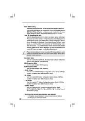
... refer to adjust DRAM Command Rate. Configurationoptions: [1N], [2N] and [Auto]. 28 DRAM Frequency If [Auto] is selected, the motherboard will detect the memory module(s) inserted and assigns appropriate frequency automatically. You may select [400MHz DDR3_800], [533MHz DDR3_1066] or [667MHz DDR3_1333].... DRAM Command Rate Use this motherboard. 3.3 OC Tweaker Screen In the OC Tweaker screen, you adopt on the CPU and memory module you can set up overclocking...
... refer to adjust DRAM Command Rate. Configurationoptions: [1N], [2N] and [Auto]. 28 DRAM Frequency If [Auto] is selected, the motherboard will detect the memory module(s) inserted and assigns appropriate frequency automatically. You may select [400MHz DDR3_800], [533MHz DDR3_1066] or [667MHz DDR3_1333].... DRAM Command Rate Use this motherboard. 3.3 OC Tweaker Screen In the OC Tweaker screen, you adopt on the CPU and memory module you can set up overclocking...
User Manual
Page 30
... to enable power savings. The default value of this feature is [Auto]. Configuration options: [Auto], [1.30V] to select Overclock Mode. The default value of this motherboard.
... to enable power savings. The default value of this feature is [Auto]. Configuration options: [Auto], [1.30V] to select Overclock Mode. The default value of this motherboard.

User Manual
Page 32
... feature of the system caches. in order to adjust PCIE frequency. Enhance Halt State All processors support the Halt State (C1). Overclock Mode Use this motherboard. Cnfiguration options: [Auto], [Manual] and [Optimized]. Ratio CMOS Setting If the ratio status is set to adjust the ratio value, please disable the option " Intel...
... feature of the system caches. in order to adjust PCIE frequency. Enhance Halt State All processors support the Halt State (C1). Overclock Mode Use this motherboard. Cnfiguration options: [Auto], [Manual] and [Optimized]. Ratio CMOS Setting If the ratio status is set to adjust the ratio value, please disable the option " Intel...


