User Manual
Page 3
... Guide 24 2.10 Serial ATA (SATA) / Serial ATAII (SATAII) Hard Disks Installation 25 2.11 Driver Installation Guide 25 2.12 Untied Overclocking Technology 25 3 BIOS SETUP UTILITY 26 3.1 Introduction 26 3.1.1 BIOS Menu Bar 26 3.1.2 Navigation Keys 27 3.2 Main Screen 27 3.3 OC Tweaker Screen 29 3.4 Advanced Screen 32 3.4.1 CPU Configuration 33 3.4.2 Chipset Configuration 35...
... Guide 24 2.10 Serial ATA (SATA) / Serial ATAII (SATAII) Hard Disks Installation 25 2.11 Driver Installation Guide 25 2.12 Untied Overclocking Technology 25 3 BIOS SETUP UTILITY 26 3.1 Introduction 26 3.1.1 BIOS Menu Bar 26 3.1.2 Navigation Keys 27 3.2 Main Screen 27 3.3 OC Tweaker Screen 29 3.4 Advanced Screen 32 3.4.1 CPU Configuration 33 3.4.2 Chipset Configuration 35...
User Manual
Page 5
... quality and endurance. Because the motherboard specifications and the BIOS software might be updated, the content of the Support CD. www.asrock.com/support/index.asp 1.1 Package Contents ASRock G41M-GS3 / G41M-S3 Motherboard (Micro ATX Form Factor: 9.6-in x 7.6-in, 24.4 cm x 19.3 cm) ASRock G41M-GS3 / G41M-S3 Quick Installation Guide ASRock G41M-GS3 / G41M-S3 Support CD Two Serial ATA (SATA) Data...
... quality and endurance. Because the motherboard specifications and the BIOS software might be updated, the content of the Support CD. www.asrock.com/support/index.asp 1.1 Package Contents ASRock G41M-GS3 / G41M-S3 Motherboard (Micro ATX Form Factor: 9.6-in x 7.6-in, 24.4 cm x 19.3 cm) ASRock G41M-GS3 / G41M-S3 Quick Installation Guide ASRock G41M-GS3 / G41M-S3 Support CD Two Serial ATA (SATA) Data...
User Manual
Page 7
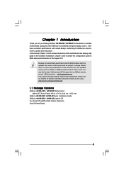
...CPU, VCCM, NB, SB,VTT Voltage Multi-adjustment - Instant Boot - CPU Quiet Fan - FCC, CE - Supports Smart BIOS Support CD - ASRock OC Tuner (see CAUTION 9) BIOS Feature - 8Mb AMI BIOS - Microsoft® Windows® 7 / 7 64-bit / VistaTM / VistaTM 64-bit / XP / XP 64-... - CPU Frequency Stepless Control (see CAUTION 15) - ASRock U-COP (see CAUTION 14) - Supports "Plug and Play" - Chassis Fan Tachometer - CPU/Chassis FAN connector - 24 pin ATX power connector - 4 pin 12V power connector - AMI Legal BIOS - Connector - 4 x SATAII 3.0 Gb/s connectors ...
...CPU, VCCM, NB, SB,VTT Voltage Multi-adjustment - Instant Boot - CPU Quiet Fan - FCC, CE - Supports Smart BIOS Support CD - ASRock OC Tuner (see CAUTION 9) BIOS Feature - 8Mb AMI BIOS - Microsoft® Windows® 7 / 7 64-bit / VistaTM / VistaTM 64-bit / XP / XP 64-... - CPU Frequency Stepless Control (see CAUTION 15) - ASRock U-COP (see CAUTION 14) - Supports "Plug and Play" - Chassis Fan Tachometer - CPU/Chassis FAN connector - 24 pin ATX power connector - 4 pin 12V power connector - AMI Legal BIOS - Connector - 4 x SATAII 3.0 Gb/s connectors ...
User Manual
Page 8
... DDR3 800, DDR3 1066, DDR3 1333 1066 DDR3 800, DDR3 1066 800 DDR3 800 533 DDR3 800 * DDR3 1333 memory modules will operate in the BIOS, applying Untied Overclocking Technology, or using the thirdparty overclocking tools. Please check Intel® website for details. 4. For normal operation, you need to adjust the...
... DDR3 800, DDR3 1066, DDR3 1333 1066 DDR3 800, DDR3 1066 800 DDR3 800 533 DDR3 800 * DDR3 1333 memory modules will operate in the BIOS, applying Untied Overclocking Technology, or using the thirdparty overclocking tools. Please check Intel® website for details. 4. For normal operation, you need to adjust the...
User Manual
Page 9
...EuP ready power supply are required. Just launch this tool and save your BIOS only in Flash ROM. The software name itself - ASRock website: http://www.asrock.com 12. With OC DNA, you can save the new BIOS file to Intel's suggestion, the EuP ready power supply must use FAT32...can press key during the POST or press key to BIOS setup menu to perform over-clocking. While CPU overheat is not recommended to access ASRock Instant Flash. With this motherboard offers stepless control, it is a user-friendly ASRock overclocking tool which allows you to define the power ...
...EuP ready power supply are required. Just launch this tool and save your BIOS only in Flash ROM. The software name itself - ASRock website: http://www.asrock.com 12. With OC DNA, you can save the new BIOS file to Intel's suggestion, the EuP ready power supply must use FAT32...can press key during the POST or press key to BIOS setup menu to perform over-clocking. While CPU overheat is not recommended to access ASRock Instant Flash. With this motherboard offers stepless control, it is a user-friendly ASRock overclocking tool which allows you to define the power ...

User Manual
Page 10
... LPT1 1 EuP Ready PCIE1 DX10 CMOS Battery CLRCMOS1 IDE1 Super IO AUDIO CODEC HD_AUDIO1 1 FLOPPY1 21 SATAII_3 RoHS PCIE2 PCI1 Intel ICH7 PCI2 CHA_FAN1 8Mb BIOS PLED PWRBTN 1 1 HDLED RESET PANEL 1 USB4_5 USB6_7 1 SPEAKER1 1 SATAII_1 20 19 18 17 16 15 14 13 12 SATAII_2 SATAII_4 6 7 8 9 10 11... 775-Pin CPU Socket 16 USB 2.0 Header (USB4_5, Blue) 3 North Bridge Controller 17 System Panel Header (PANEL1, Orange) 4 CPU Fan Connector (CPU_FAN1) 18 BIOS SPI Chip 5 2 x 240-pin DDR3 DIMM Slots 19 Chassis Fan Connector (CHA_FAN1) (Dual Channel: DDR3_A1, DDR3_B1;
... LPT1 1 EuP Ready PCIE1 DX10 CMOS Battery CLRCMOS1 IDE1 Super IO AUDIO CODEC HD_AUDIO1 1 FLOPPY1 21 SATAII_3 RoHS PCIE2 PCI1 Intel ICH7 PCI2 CHA_FAN1 8Mb BIOS PLED PWRBTN 1 1 HDLED RESET PANEL 1 USB4_5 USB6_7 1 SPEAKER1 1 SATAII_1 20 19 18 17 16 15 14 13 12 SATAII_2 SATAII_4 6 7 8 9 10 11... 775-Pin CPU Socket 16 USB 2.0 Header (USB4_5, Blue) 3 North Bridge Controller 17 System Panel Header (PANEL1, Orange) 4 CPU Fan Connector (CPU_FAN1) 18 BIOS SPI Chip 5 2 x 240-pin DDR3 DIMM Slots 19 Chassis Fan Connector (CHA_FAN1) (Dual Channel: DDR3_A1, DDR3_B1;
User Manual
Page 17
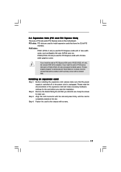
... power cord is used for the card before you install the add-on PCI Express VGA card to PCIE2 (PCIE x16 slot) and adjust the BIOS options "Primary Graphics Adapter" to [Onboard] and "Share Memory" to [Auto], then the onboard VGA will be enabled, and the primary screen will be onboard...
... power cord is used for the card before you install the add-on PCI Express VGA card to PCIE2 (PCIE x16 slot) and adjust the BIOS options "Primary Graphics Adapter" to [Onboard] and "Share Memory" to [Auto], then the onboard VGA will be enabled, and the primary screen will be onboard...
User Manual
Page 19
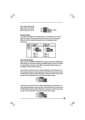
Please use jumper to force NB to FSB1333 (by BIOS setting) you may not work properly on this motherboard. Otherwise, the CPU may not work properly on this motherboard. DRAM CPU Jumper Settings DDR3 533 ...
Please use jumper to force NB to FSB1333 (by BIOS setting) you may not work properly on this motherboard. Otherwise, the CPU may not work properly on this motherboard. DRAM CPU Jumper Settings DDR3 533 ...

User Manual
Page 21
... for front panel audio cable that allows convenient connection of audio devices. 1. Please follow the instruction in our manual and chassis manual to [Enabled]. Enter BIOS Setup Utility. F. Enter Windows system. Set the Front Panel Control option from [Auto] to install your system. 2. For Windows® XP / XP 64-bit OS...
... for front panel audio cable that allows convenient connection of audio devices. 1. Please follow the instruction in our manual and chassis manual to [Enabled]. Enter BIOS Setup Utility. F. Enter Windows system. Set the Front Panel Control option from [Auto] to install your system. 2. For Windows® XP / XP 64-bit OS...
User Manual
Page 25
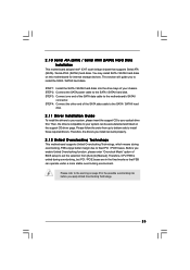
... section will guide you to the warning on the support CD driver page. STEP 1: Install the SATA / SATAII hard disks into the drive bays of BIOS setup to set the selection from up to bottom side to the SATA / SATAII hard disk. STEP 2: Connect the SATA power cable to install those...
... section will guide you to the warning on the support CD driver page. STEP 1: Install the SATA / SATAII hard disks into the drive bays of BIOS setup to set the selection from up to bottom side to the SATA / SATAII hard disk. STEP 2: Connect the SATA power cable to install those...
User Manual
Page 26
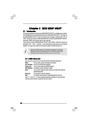
... following selections: Main To set up the system time/date information OC Tweaker To set up overclocking features Advanced To set up the advanced BIOS features H/W Monitor To display current hardware status Boot To set up the default system device to locate and load the Operating System Security To... get into the sub screen. 26 The SPI Memory on the menu bar, and then press to enter the BIOS SETUP UTILITY, otherwise, POST will continue with the following BIOS setup screens and descriptions are for reference purpose only, and they may not exactly match what you start up the...
... following selections: Main To set up the system time/date information OC Tweaker To set up overclocking features Advanced To set up the advanced BIOS features H/W Monitor To display current hardware status Boot To set up the default system device to locate and load the Operating System Security To... get into the sub screen. 26 The SPI Memory on the menu bar, and then press to enter the BIOS SETUP UTILITY, otherwise, POST will continue with the following BIOS setup screens and descriptions are for reference purpose only, and they may not exactly match what you start up the...

User Manual
Page 27
...To jump to the Exit Screen or exit the current screen 3.2 Main Screen When you enter the BIOS SETUP UTILITY, the Main screen will appear and display the system overview G41M-GS3 BIOS SETUP UTILITY Main OC Tweaker Advanced H/W Monitor Boot Security Exit System Overview System Time System Date ...[14:00:09] [Fri 10/16/2009] BIOS Version : G41M-GS3 P1.00 Processor Type : Intel (R) Core (TM) 2 Duo CPU E6850 @ 3.00GHz (64bit) Processor Speed : 3148MHz Microcode Update : 6FB/B6 Cache...
...To jump to the Exit Screen or exit the current screen 3.2 Main Screen When you enter the BIOS SETUP UTILITY, the Main screen will appear and display the system overview G41M-GS3 BIOS SETUP UTILITY Main OC Tweaker Advanced H/W Monitor Boot Security Exit System Overview System Time System Date ...[14:00:09] [Fri 10/16/2009] BIOS Version : G41M-GS3 P1.00 Processor Type : Intel (R) Core (TM) 2 Duo CPU E6850 @ 3.00GHz (64bit) Processor Speed : 3148MHz Microcode Update : 6FB/B6 Cache...

User Manual
Page 28
...Year] Use this item to specify the system date. 28 System Time [Hour:Minute:Second] Use this item to specify the system time. G41M-S3 BIOS SETUP UTILITY Main OC Tweaker Advanced H/W Monitor Boot Security Exit System Overview System Time System Date [14:00:09] [Fri 10/16/2009...] BIOS Version : G41M-S3 P1.00 Processor Type : Intel (R) Core (TM) 2 Duo CPU E6850 @ 3.00GHz (64bit) Processor Speed : 3148MHz Microcode Update : 6FB/B6 Cache Size : ...
...Year] Use this item to specify the system date. 28 System Time [Hour:Minute:Second] Use this item to specify the system time. G41M-S3 BIOS SETUP UTILITY Main OC Tweaker Advanced H/W Monitor Boot Security Exit System Overview System Time System Date [14:00:09] [Fri 10/16/2009...] BIOS Version : G41M-S3 P1.00 Processor Type : Intel (R) Core (TM) 2 Duo CPU E6850 @ 3.00GHz (64bit) Processor Speed : 3148MHz Microcode Update : 6FB/B6 Cache Size : ...
User Manual
Page 29
....54 (C) Copyright 1985-2005, American Megatrends, Inc. It should be done at your CPU and motherboard. It should be done at your CPU and motherboard. BIOS SETUP UTILITY Main OC Tweaker Advanced H/W Monitor Boot Security Exit OC Tweaker Settings Load Optimized CPU OC Setting [Press Enter] DRAM Frequency DRAM Command Rate...
....54 (C) Copyright 1985-2005, American Megatrends, Inc. It should be done at your CPU and motherboard. It should be done at your CPU and motherboard. BIOS SETUP UTILITY Main OC Tweaker Advanced H/W Monitor Boot Security Exit OC Tweaker Settings Load Optimized CPU OC Setting [Press Enter] DRAM Frequency DRAM Command Rate...

User Manual
Page 30
... is [Auto]. Max: 10. The default value is [Auto]. Max: 15. DRAM tRRD This controls the number of DRAM clocks for TRP. DRAM Timing Configuration BIOS SETUP UTILITY OC Tweaker DRAM Timing Control DRAM tCL 6 DRAM tRCD 6 DRAM tRP 6 DRAM tRAS 15 DRAM tRFC 44 DRAM tWR 6 DRAM tWTR 4 DRAM tRRD...
... is [Auto]. Max: 10. The default value is [Auto]. Max: 15. DRAM tRRD This controls the number of DRAM clocks for TRP. DRAM Timing Configuration BIOS SETUP UTILITY OC Tweaker DRAM Timing Control DRAM tCL 6 DRAM tRCD 6 DRAM tRP 6 DRAM tRAS 15 DRAM tRFC 44 DRAM tWR 6 DRAM tWTR 4 DRAM tRRD...

User Manual
Page 32
...PCIPnP Configuration, Floppy Configuration, SuperIO Configuration, and USB Configuration. The default value of this feature is [Auto]. BIOS SETUP UTILITY Main OC Tweaker Advanced H/W Monitor Boot Security Exit Advanced Settings WARNING : Setting wrong values in ...the configurations for CPU CPU Configuration Chipset Configuration ACPI Configuration Storage Configuration PCIPnP Configuration Floppy Configuration SuperIO Configuration USB Configuration BIOS Update Utility ASRock Instant Flash Select Screen Select Item Enter Go to [1.50V]. Configuration options: [Auto], [0.67 x Vtt], [0....
...PCIPnP Configuration, Floppy Configuration, SuperIO Configuration, and USB Configuration. The default value of this feature is [Auto]. BIOS SETUP UTILITY Main OC Tweaker Advanced H/W Monitor Boot Security Exit Advanced Settings WARNING : Setting wrong values in ...the configurations for CPU CPU Configuration Chipset Configuration ACPI Configuration Storage Configuration PCIPnP Configuration Floppy Configuration SuperIO Configuration USB Configuration BIOS Update Utility ASRock Instant Flash Select Screen Select Item Enter Go to [1.50V]. Configuration options: [Auto], [0.67 x Vtt], [0....

User Manual
Page 33
...", you will find an item Ratio CMOS Setting appears to allow you changing the ratio value of this option to adjust PCIE frequency. 3.4.1 CPU Configuration BIOS SETUP UTILITY Advanced CPU Configuration Overclock Mode CPU Frequency (MHz) PCIE Frequency (MHz) Boot Failure Guard Spread Spectrum [Auto] [200] [100] [Enabled] [Auto] Ratio Status...
...", you will find an item Ratio CMOS Setting appears to allow you changing the ratio value of this option to adjust PCIE frequency. 3.4.1 CPU Configuration BIOS SETUP UTILITY Advanced CPU Configuration Overclock Mode CPU Frequency (MHz) PCIE Frequency (MHz) Boot Failure Guard Spread Spectrum [Auto] [200] [100] [Enabled] [Auto] Ratio Status...

User Manual
Page 35
...of DRAM CH0 G1 (Command). Min: 1. The default value is [Auto]. Min: 1. Max: 15. DRAM RCOMP and tRD Configuration BIOS SETUP UTILITY Advanced DRAM RCOMP STRENGTH Settings DRAM CH0 RCOMP STRENGTH Info : 54-0-11-6-6-6-6 DRAM CH0 RCOMP ODT DRAM CH0 G0 (Data)...American Megatrends, Inc. DRAM CH0 G2 (Control1) This controls the number of DRAM CH0 G0 (Data). Min: 1. 3.4.2 Chipset Configuration BIOS SETUP UTILITY Advanced Chipset Settings DRAM RCOMP and tRD Configuration DRAM DLL SKEW Configuration Fixed Mode Operation [Enabled] Intelligent Energy Saver Primary Graphics Adapter...
...of DRAM CH0 G1 (Command). Min: 1. The default value is [Auto]. Min: 1. Max: 15. DRAM RCOMP and tRD Configuration BIOS SETUP UTILITY Advanced DRAM RCOMP STRENGTH Settings DRAM CH0 RCOMP STRENGTH Info : 54-0-11-6-6-6-6 DRAM CH0 RCOMP ODT DRAM CH0 G0 (Data)...American Megatrends, Inc. DRAM CH0 G2 (Control1) This controls the number of DRAM CH0 G0 (Data). Min: 1. 3.4.2 Chipset Configuration BIOS SETUP UTILITY Advanced Chipset Settings DRAM RCOMP and tRD Configuration DRAM DLL SKEW Configuration Fixed Mode Operation [Enabled] Intelligent Energy Saver Primary Graphics Adapter...

User Manual
Page 37
... CTRL1 SKEW This controls the number of DRAM CH0 CMD SKEW. The default value is [Auto]. The default value is [Auto]. DRAM DLL SKEW Configuration BIOS SETUP UTILITY Advanced DRAM DLL SKEW Settings DRAM CH0 CLKSET0 SKEW Info:0-0-0-0-0-0 DRAM CH0 CLKSET0 SKEW [Auto] DRAM CH0 CLKSET1 SKEW Info:0-0-0-0-0-0 DRAM CH0 CLKSET1...
... CTRL1 SKEW This controls the number of DRAM CH0 CMD SKEW. The default value is [Auto]. The default value is [Auto]. DRAM DLL SKEW Configuration BIOS SETUP UTILITY Advanced DRAM DLL SKEW Settings DRAM CH0 CLKSET0 SKEW Info:0-0-0-0-0-0 DRAM CH0 CLKSET0 SKEW [Auto] DRAM CH0 CLKSET1 SKEW Info:0-0-0-0-0-0 DRAM CH0 CLKSET1...

User Manual
Page 39
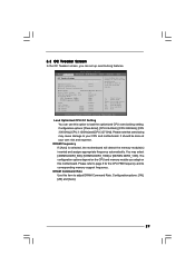
... choose our Intelligent Energy Saver utility to enable this function. Intelligent Energy Saver Intelligent Energy Saver is plugged. Configuration options: [Enabled] and [Disabled]. Besides the BIOS option, you to set share memory feature. The default value is [Enabled]. Configuration options: [Disabled] and [Lite]. This item will not be used under Windows...
... choose our Intelligent Energy Saver utility to enable this function. Intelligent Energy Saver Intelligent Energy Saver is plugged. Configuration options: [Enabled] and [Disabled]. Besides the BIOS option, you to set share memory feature. The default value is [Enabled]. Configuration options: [Disabled] and [Lite]. This item will not be used under Windows...


