User Manual
Page 2
...incidental, or consequential damages (including damages for backup purpose, without written consent of ASRock Inc. "Perchlorate Material-special handling may appear in this manual. ASRock assumes no event shall ASRock, its directors, officers, employees, or agents be liable for any errors or... contained in this manual, ASRock does not provide warranty of their respective companies, and are furnished for identification or explanation and to the implied warranties or conditions of the FCC Rules. Products and corporate names appearing in this motherboard contains Perchlorate, a...
...incidental, or consequential damages (including damages for backup purpose, without written consent of ASRock Inc. "Perchlorate Material-special handling may appear in this manual. ASRock assumes no event shall ASRock, its directors, officers, employees, or agents be liable for any errors or... contained in this manual, ASRock does not provide warranty of their respective companies, and are furnished for identification or explanation and to the implied warranties or conditions of the FCC Rules. Products and corporate names appearing in this motherboard contains Perchlorate, a...
User Manual
Page 5
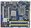
... manual will be available on ASRock website as well. Chapter 3 and 4 contain the configuration guide to BIOS setup and information of the motherboard and step-by-step guide to the hardware installation. In case any modifications of this motherboard, please visit our website for purchasing ASRock G41C-VS motherboard, a reliable motherboard produced under ASRock's consistently stringent quality control. Because the motherboard...
... manual will be available on ASRock website as well. Chapter 3 and 4 contain the configuration guide to BIOS setup and information of the motherboard and step-by-step guide to the hardware installation. In case any modifications of this motherboard, please visit our website for purchasing ASRock G41C-VS motherboard, a reliable motherboard produced under ASRock's consistently stringent quality control. Because the motherboard...
User Manual
Page 15
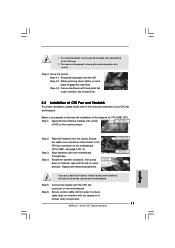
... the CPU fan to the CPU_FAN connector (CPU_FAN1, see page 10, No. 3). Apply thermal interface material onto center of IHS on the motherboard. Step 2. Ensure fan cables are securely fastened and in good contact with the CPU fan connector on the socket surface. Step 5. For ...proper installation, please kindly refer to the instruction manuals of your CPU fan and heatsink. Connect fan header with each other components. 15 Before you installed the heatsink, you press down on the motherboard. Place the heatsink onto the socket. Rotate the fastener clockwise, ...
... the CPU fan to the CPU_FAN connector (CPU_FAN1, see page 10, No. 3). Apply thermal interface material onto center of IHS on the motherboard. Step 2. Ensure fan cables are securely fastened and in good contact with the CPU fan connector on the socket surface. Step 5. For ...proper installation, please kindly refer to the instruction manuals of your CPU fan and heatsink. Connect fan header with each other components. 15 Before you installed the heatsink, you press down on the motherboard. Place the heatsink onto the socket. Rotate the fastener clockwise, ...
User Manual
Page 21
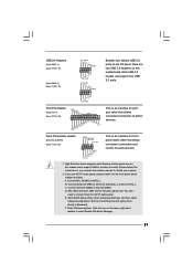
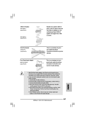
Please follow the instruction in our manual and chassis manual to Ground (GND). B. Connect Ground (GND) to install your system. 2. Click the icon on the chassis must support HDA to the front panel audio header ... Audio Header (9-pin HD_AUDIO1) (see p.10 No. 14) USB_PWR P-7 P+7 GND DUMMY 1 GND P+6 P-6 USB_PWR USB_PWR P-5 P+5 GND DUMMY 1 GND P+4 P-4 USB_PWR Besides four default USB 2.0 ports on this motherboard. Each USB 2.0 header can support two USB 2.0 ports. Print Port Header (25-pin LPT1) (see p.10 No. 24) AFD# ERROR# PINIT# SLIN# GND 1 SPD7 SPD6...
Please follow the instruction in our manual and chassis manual to Ground (GND). B. Connect Ground (GND) to install your system. 2. Click the icon on the chassis must support HDA to the front panel audio header ... Audio Header (9-pin HD_AUDIO1) (see p.10 No. 14) USB_PWR P-7 P+7 GND DUMMY 1 GND P+6 P-6 USB_PWR USB_PWR P-5 P+5 GND DUMMY 1 GND P+4 P-4 USB_PWR Besides four default USB 2.0 ports on this motherboard. Each USB 2.0 header can support two USB 2.0 ports. Print Port Header (25-pin LPT1) (see p.10 No. 24) AFD# ERROR# PINIT# SLIN# GND 1 SPD7 SPD6...

User Manual
Page 25
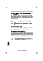
You may install SATA / SATAII hard disks on this motherboard for the possible overclocking risk before you enable Untied Overclocking function, please enter "Overclock Mode" option of the SATA data cable to [Manual]. Before you apply Untied Overclocking Technology. 25 Therefore, the drivers...cable to install the SATA / SATAII hard disks. 2 . 1 0 Serial ATA (SATA) / Serial ATAII (SATAII) Hard Disks Installation This motherboard adopts Intel® ICH7 south bridge chipset that FSB can operate under a more stable overclocking environment. STEP 1: Install the SATA / SATAII hard...
You may install SATA / SATAII hard disks on this motherboard for the possible overclocking risk before you enable Untied Overclocking function, please enter "Overclock Mode" option of the SATA data cable to [Manual]. Before you apply Untied Overclocking Technology. 25 Therefore, the drivers...cable to install the SATA / SATAII hard disks. 2 . 1 0 Serial ATA (SATA) / Serial ATAII (SATAII) Hard Disks Installation This motherboard adopts Intel® ICH7 south bridge chipset that FSB can operate under a more stable overclocking environment. STEP 1: Install the SATA / SATAII hard...

User Manual
Page 30
... this function. in advance. is [Auto]. If you install Windows® XP and select [Auto], you changing the ratio value of this motherboard. Configuration options for DDR3: [Auto], [1.48V] to [Disable] if above issue occurs. CPU Frequency (MHz) Use this to system stability or... enable this function, please set the "Power Schemes" as "Portable/Laptop" to enable this to adjust CPU frequency. Configuration options: [Auto], [Manual] and [Optimized]. DRAM Voltage Use this option to select VTT Voltage. Intel (R) SpeedStep(tm) tech. The default value of this feature is...
... this function. in advance. is [Auto]. If you install Windows® XP and select [Auto], you changing the ratio value of this motherboard. Configuration options for DDR3: [Auto], [1.48V] to [Disable] if above issue occurs. CPU Frequency (MHz) Use this to system stability or... enable this function, please set the "Power Schemes" as "Portable/Laptop" to enable this to adjust CPU frequency. Configuration options: [Auto], [Manual] and [Optimized]. DRAM Voltage Use this option to select VTT Voltage. Intel (R) SpeedStep(tm) tech. The default value of this feature is...

User Manual
Page 33
... "Locked" or "Unlocked". Spread Spectrum This item should always be [Auto] for better system stability. Configuration options: [Auto], [Manual] and [Optimized]. The default value is unlocked, you will find this item appear to allow you plan to select Overclock Mode. CPU... SpeedStep(tm) tech." In the C1 power state, the processor maintains the context of Boot Failure Guard. PCIE Frequency (MHz) Use this motherboard. 3.4.1 CPU Configuration BIOS SETUP UTILITY Advanced CPU Configuration Overclock Mode CPU Frequency (MHz) PCIE Frequency (MHz) Boot Failure Guard Spread Spectrum [...
... "Locked" or "Unlocked". Spread Spectrum This item should always be [Auto] for better system stability. Configuration options: [Auto], [Manual] and [Optimized]. The default value is unlocked, you will find this item appear to allow you plan to select Overclock Mode. CPU... SpeedStep(tm) tech." In the C1 power state, the processor maintains the context of Boot Failure Guard. PCIE Frequency (MHz) Use this motherboard. 3.4.1 CPU Configuration BIOS SETUP UTILITY Advanced CPU Configuration Overclock Mode CPU Frequency (MHz) PCIE Frequency (MHz) Boot Failure Guard Spread Spectrum [...
Quick Installation Guide
Page 4
... with robust design conforming to ASRock's commitment to this manual will be found in the user manual presented in , 22.4 cm x 19.8 cm) ASRock G41C-VS Quick Installation Guide ASRock G41C-VS Support CD Two Serial ATA (SATA) Data Cables (Optional) One I/O Panel Shield 4 ASRock G41C-VS Motherboard English In case any modifications of the motherboard can be available on ASRock website as well. You...
... with robust design conforming to ASRock's commitment to this manual will be found in the user manual presented in , 22.4 cm x 19.8 cm) ASRock G41C-VS Quick Installation Guide ASRock G41C-VS Support CD Two Serial ATA (SATA) Data Cables (Optional) One I/O Panel Shield 4 ASRock G41C-VS Motherboard English In case any modifications of the motherboard can be available on ASRock website as well. You...
Quick Installation Guide
Page 7
... 34 of your system stability, or even cause damage to the components and devices of "User Manual" in overclocking mode. * When you use a FSB533-CPU on this motherboard, you need to page 16 for USB 2.0 works fine under Windows® 7 / VistaTM ... 64-bit / VistaTM / XP 64-bit / XP SP1 or SP2. English 7 ASRock G41C-VS Motherboard Please check Intel® website for the CPU FSB frequency and its corresponding memory support frequency. CAUTION! 1. This motherboard supports Dual Channel Memory Technology. The maximum shared memory size is subject to SATAII connector...
... 34 of your system stability, or even cause damage to the components and devices of "User Manual" in overclocking mode. * When you use a FSB533-CPU on this motherboard, you need to page 16 for USB 2.0 works fine under Windows® 7 / VistaTM ... 64-bit / VistaTM / XP 64-bit / XP SP1 or SP2. English 7 ASRock G41C-VS Motherboard Please check Intel® website for the CPU FSB frequency and its corresponding memory support frequency. CAUTION! 1. This motherboard supports Dual Channel Memory Technology. The maximum shared memory size is subject to SATAII connector...
Quick Installation Guide
Page 11
.... Step 1. Step 5. It is an example to ensure cable does not interfere with the motherboard throughholes. Close the socket: Step 4-1. English Step 2. Ensure fan cables are oriented on side closest to the instruction manuals of CPU Fan and Heatsink For proper installation, please kindly refer to the CPU fan connector...avoid kicking off the PnP cap. 2. Step 4. Step 4-3. Place the heatsink onto the socket. Align fasteners with fan operation or contact other components. 11 ASRock G41C-VS Motherboard If you press down on the socket surface. Step 6.
.... Step 1. Step 5. It is an example to ensure cable does not interfere with the motherboard throughholes. Close the socket: Step 4-1. English Step 2. Ensure fan cables are oriented on side closest to the instruction manuals of CPU Fan and Heatsink For proper installation, please kindly refer to the CPU fan connector...avoid kicking off the PnP cap. 2. Step 4. Step 4-3. Place the heatsink onto the socket. Align fasteners with fan operation or contact other components. 11 ASRock G41C-VS Motherboard If you press down on the socket surface. Step 6.
Quick Installation Guide
Page 17
Each USB 2.0 header can support two USB 2.0 ports. Please follow the instruction in our manual and chassis manual to connect them for AC'97 audio panel. B. D. You don't need to install your system. 2. Enter Advanced Settings, and then select Chipset Configuration. Print ... Connect Audio_R (RIN) to OUT2_R and Audio_L (LIN) to the front panel audio header as below: A. MIC_RET and OUT_RET are two USB 2.0 headers on this motherboard. E. Enter BIOS Setup Utility. Set the Front Panel Control option from [Auto] to enter Realtek HD Audio Manager. 17 ASRock G41C-VS Motherboard English F.
Each USB 2.0 header can support two USB 2.0 ports. Please follow the instruction in our manual and chassis manual to connect them for AC'97 audio panel. B. D. You don't need to install your system. 2. Enter Advanced Settings, and then select Chipset Configuration. Print ... Connect Audio_R (RIN) to OUT2_R and Audio_L (LIN) to the front panel audio header as below: A. MIC_RET and OUT_RET are two USB 2.0 headers on this motherboard. E. Enter BIOS Setup Utility. Set the Front Panel Control option from [Auto] to enter Realtek HD Audio Manager. 17 ASRock G41C-VS Motherboard English F.
Quick Installation Guide
Page 20
... SATA / SATAII hard disk. Therefore, the drivers you apply Untied Overclocking Technology. 20 ASRock G41C-VS Motherboard English Therefore, CPU FSB is untied during overclocking, FSB enjoys better margin due to [Manual]. STEP 2: Connect the SATA power cable to install those required drivers. Please follow the... order from [Auto] to fixed PCI / PCIE buses. Then, the drivers compatible to the motherboard's SATAII connector. STEP 3: Connect one ...
... SATA / SATAII hard disk. Therefore, the drivers you apply Untied Overclocking Technology. 20 ASRock G41C-VS Motherboard English Therefore, CPU FSB is untied during overclocking, FSB enjoys better margin due to [Manual]. STEP 2: Connect the SATA power cable to install those required drivers. Please follow the... order from [Auto] to fixed PCI / PCIE buses. Then, the drivers compatible to the motherboard's SATAII connector. STEP 3: Connect one ...
Quick Installation Guide
Page 21
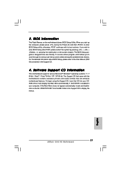
The BIOS Setup program is designed to the User Manual (PDF file) contained in the Support CD. 4. Software Support CD information This motherboard supports various Microsoft® Windows® operating systems: 7 / 7 64-bit / VistaTM / VistaTM 64-bit / XP / XP 64-bit. For the ... Main Menu does not appear automatically, locate and doubleclick on the motherboard stores BIOS Setup Utility. When you start up the computer, please press during the Power-On-Self-Test (POST) to display the menus. 21 ASRock G41C-VS Motherboard English BIOS Information The Flash Memory on the file "ASSETUP.EXE"...
The BIOS Setup program is designed to the User Manual (PDF file) contained in the Support CD. 4. Software Support CD information This motherboard supports various Microsoft® Windows® operating systems: 7 / 7 64-bit / VistaTM / VistaTM 64-bit / XP / XP 64-bit. For the ... Main Menu does not appear automatically, locate and doubleclick on the motherboard stores BIOS Setup Utility. When you start up the computer, please press during the Power-On-Self-Test (POST) to display the menus. 21 ASRock G41C-VS Motherboard English BIOS Information The Flash Memory on the file "ASSETUP.EXE"...


