
User Manual
Page 3
...Specifications 6 1.3 Unique Features 9 1.4 Motherboard Layout 11 1.5 I/O Panel 12 2 Installation 13 2.1 Screw Holes 13 2.2 Pre-installation Precautions 13 2.3 CPU Installation 14 2.4 Installation of Heatsink and CPU fan 16 2.5 Installation of Memory Modules (DIMM 17 2.6 Expansion Slots (PCI and PCI Express Slots 19 2.7 Jumpers Setup 20 2.8 Onboard Headers and Connectors 21 2.9 Driver Installation Guide 25 2.10 Untied Overclocking Technology 25 3 BIOS SETUP UTILITY 26 3.1 Introduction 26 3.1.1 BIOS Menu Bar 26 3.1.2 Navigation Keys 27 3.2 Main Screen 27 3.3 OC Tweaker Screen...
...Specifications 6 1.3 Unique Features 9 1.4 Motherboard Layout 11 1.5 I/O Panel 12 2 Installation 13 2.1 Screw Holes 13 2.2 Pre-installation Precautions 13 2.3 CPU Installation 14 2.4 Installation of Heatsink and CPU fan 16 2.5 Installation of Memory Modules (DIMM 17 2.6 Expansion Slots (PCI and PCI Express Slots 19 2.7 Jumpers Setup 20 2.8 Onboard Headers and Connectors 21 2.9 Driver Installation Guide 25 2.10 Untied Overclocking Technology 25 3 BIOS SETUP UTILITY 26 3.1 Introduction 26 3.1.1 BIOS Menu Bar 26 3.1.2 Navigation Keys 27 3.2 Main Screen 27 3.3 OC Tweaker Screen...

User Manual
Page 5
....asrock.com/support/index.asp 1.1 Package Contents ASRock G41C-GS R2.0 Motherboard (Micro ATX Form Factor) ASRock G41C-GS R2.0 Quick Installation Guide ASRock G41C-GS R2.0 Support CD Two Serial ATA (SATA) Data Cables (Optional) One I/O Panel Shield 5 Because the motherboard specifications and the BIOS software might be updated, the content of this manual, chapter 1 and 2 contain introduction of the Support CD. Chapter 3 and 4 contain the configuration guide to BIOS setup and information of the motherboard and step-by-step guide to change without further notice. In case...
....asrock.com/support/index.asp 1.1 Package Contents ASRock G41C-GS R2.0 Motherboard (Micro ATX Form Factor) ASRock G41C-GS R2.0 Quick Installation Guide ASRock G41C-GS R2.0 Support CD Two Serial ATA (SATA) Data Cables (Optional) One I/O Panel Shield 5 Because the motherboard specifications and the BIOS software might be updated, the content of this manual, chapter 1 and 2 contain introduction of the Support CD. Chapter 3 and 4 contain the configuration guide to BIOS setup and information of the motherboard and step-by-step guide to change without further notice. In case...

User Manual
Page 7
...Line in / Front Speaker / Microphone Storage - 4 x SATA2 3.0 Gb/s Connectors (No support for RAID and Hot Plug) Connector - 1 x ATA100 IDE Connector (Supports 2 x IDE devices) - 1 x Floppy Connector - 1 x Print Port Header - 1 x Chassis Intrusion Header - 1 x CPU Fan Connector (4-pin) - 1 x Chassis Fan Connector (4-pin) - 1 x Power Fan Connector (3-pin) - 1 x 24 pin ATX Power Connector - 1 x 4 pin 12V Power Connector - 1 x Front Panel Audio Connector - 2 x USB 2.0 Headers (Support 4 USB 2.0 ports) (Supports ESD Protection (ASRock Full Spike Protection)) BIOS Feature - 8Mb AMI...
...Line in / Front Speaker / Microphone Storage - 4 x SATA2 3.0 Gb/s Connectors (No support for RAID and Hot Plug) Connector - 1 x ATA100 IDE Connector (Supports 2 x IDE devices) - 1 x Floppy Connector - 1 x Print Port Header - 1 x Chassis Intrusion Header - 1 x CPU Fan Connector (4-pin) - 1 x Chassis Fan Connector (4-pin) - 1 x Power Fan Connector (3-pin) - 1 x 24 pin ATX Power Connector - 1 x 4 pin 12V Power Connector - 1 x Front Panel Audio Connector - 2 x USB 2.0 Headers (Support 4 USB 2.0 ports) (Supports ESD Protection (ASRock Full Spike Protection)) BIOS Feature - 8Mb AMI...

User Manual
Page 22
... install your system. 2. Connect Ground (GND) to [Enabled]. 22 Set the Front Panel Control option from [Auto] to Ground (GND). Enter BIOS Setup Utility. B. MIC_RET and OUT_RET are two USB 2.0 headers on the motherboard. High Definition Audio supports Jack Sensing, but the panel wire on the I/O panel, there are for front panel audio cable that allows convenient connection of the SATA data cable can support two USB 2.0 ports. E. You don't need to the SATA / SATAII hard disk or the SATAII connector on this motherboard. Each USB 2.0 header...
... install your system. 2. Connect Ground (GND) to [Enabled]. 22 Set the Front Panel Control option from [Auto] to Ground (GND). Enter BIOS Setup Utility. B. MIC_RET and OUT_RET are two USB 2.0 headers on the motherboard. High Definition Audio supports Jack Sensing, but the panel wire on the I/O panel, there are for front panel audio cable that allows convenient connection of the SATA data cable can support two USB 2.0 ports. E. You don't need to the SATA / SATAII hard disk or the SATAII connector on this motherboard. Each USB 2.0 header...

User Manual
Page 25
... listed on page 8 for the possible overclocking risk before you apply Untied Overclocking Technology. 25 Please follow the order from [Auto] to fixed PCI / PCIE buses. Therefore, CPU FSB is untied during overclocking, FSB enjoys better margin due to [Manual]. 2.9 Driver Installation Guide To install the drivers to your system, please insert the support CD to install those required drivers. Therefore, the drivers you enable Untied Overclocking function, please enter "Overclock Mode" option of BIOS setup to set...
... listed on page 8 for the possible overclocking risk before you apply Untied Overclocking Technology. 25 Please follow the order from [Auto] to fixed PCI / PCIE buses. Therefore, CPU FSB is untied during overclocking, FSB enjoys better margin due to [Manual]. 2.9 Driver Installation Guide To install the drivers to your system, please insert the support CD to install those required drivers. Therefore, the drivers you enable Untied Overclocking function, please enter "Overclock Mode" option of BIOS setup to set...

User Manual
Page 28
... CPU FSB frequency and its corresponding memory support frequency. 28 3.3 OC Tweaker Screen In the OC Tweaker screen, you adopt DDR3 1333 pls. Please refer to Sub Screen F1 General Help F9 Load Defaults F10 Save and Exit ESC Exit v02.54 (C) Copyright 1985-2005, American Megatrends, Inc. adjust jumper set up overclocking features. BIOS SETUP UTILITY Main OC Tweaker Advanced H/W Monitor Boot Security Exit OC Tweaker Settings DRAM Frequency DRAM Timing Configuration Ratio CMOS Setting...
... CPU FSB frequency and its corresponding memory support frequency. 28 3.3 OC Tweaker Screen In the OC Tweaker screen, you adopt DDR3 1333 pls. Please refer to Sub Screen F1 General Help F9 Load Defaults F10 Save and Exit ESC Exit v02.54 (C) Copyright 1985-2005, American Megatrends, Inc. adjust jumper set up overclocking features. BIOS SETUP UTILITY Main OC Tweaker Advanced H/W Monitor Boot Security Exit OC Tweaker Settings DRAM Frequency DRAM Timing Configuration Ratio CMOS Setting...

User Manual
Page 30
... this to [Disable] if above issue occurs. Please note that enabling this item to select GLTREF Voltage. Please set this to adjust CPU frequency. Configuration options: [Auto], [1.10V] and [1.46V]. The default value of this option to select Overclock Mode. Configuration options: [Auto], [Manual] and [Optimized]. CPU Frequency (MHz) Use this feature is [Auto]. 30 PCIE Frequency (MHz) Use this feature is [Auto]. The default value of this option to system stability or compatibility issue with some power supplies. Intel...
... this to [Disable] if above issue occurs. Please note that enabling this item to select GLTREF Voltage. Please set this to adjust CPU frequency. Configuration options: [Auto], [1.10V] and [1.46V]. The default value of this option to select Overclock Mode. Configuration options: [Auto], [Manual] and [Optimized]. CPU Frequency (MHz) Use this feature is [Auto]. 30 PCIE Frequency (MHz) Use this feature is [Auto]. The default value of this option to system stability or compatibility issue with some power supplies. Intel...

User Manual
Page 33
... CPU frequency. Overclock Mode Use this option is unlocked, you plan to [Enabled], a VMM (Virtual Machine Architecture) can utilize the additional hardware capabilities provided by Vanderpool Technology. Configuration options: [Auto], [Manual] and [Optimized]. The default value is supported through the native processor instructions HLT and MWAIT and requires no hardware support from the chipset. Boot Failure Guard Enable or disable the feature of the system caches. Intel (R) Virtualization tech. On-Demand Clock Modulation [Auto] [333] [100] [Enabled] [Auto] [8] [Disabled...
... CPU frequency. Overclock Mode Use this option is unlocked, you plan to [Enabled], a VMM (Virtual Machine Architecture) can utilize the additional hardware capabilities provided by Vanderpool Technology. Configuration options: [Auto], [Manual] and [Optimized]. The default value is supported through the native processor instructions HLT and MWAIT and requires no hardware support from the chipset. Boot Failure Guard Enable or disable the feature of the system caches. Intel (R) Virtualization tech. On-Demand Clock Modulation [Auto] [333] [100] [Enabled] [Auto] [8] [Disabled...

User Manual
Page 39
... adjust the shared memory size in Intel® 4 Series Express chipset family to select [Onboard], [PCI] or [PCI Express] as [DVMT Mode]. Share Memory This allows you to support increased content protection and robustness requirements for the motherboard through efficient memory utilization. PAVP Mode Use this item to adjust PAVP mode. If you want to enable this function, please set DVMT Mode Select as the boot graphic adapter priority. Besides the BIOS option, you can...
... adjust the shared memory size in Intel® 4 Series Express chipset family to select [Onboard], [PCI] or [PCI Express] as [DVMT Mode]. Share Memory This allows you to support increased content protection and robustness requirements for the motherboard through efficient memory utilization. PAVP Mode Use this item to adjust PAVP mode. If you want to enable this function, please set DVMT Mode Select as the boot graphic adapter priority. Besides the BIOS option, you can...

User Manual
Page 41
... (Win2000 / XP) is used. ACPI HPET Table Use this motherboard to submit Windows® VistaTM certification. 3.4.4 Storage Configuration BIOS SETUP UTILITY Advanced Storage Configuration ATA/IDE Configuration SATAII_1 SATAII_2 SATAII_3 SATAII_4 IDE1 Master IDE1 Slave [Enhanced] [Hard Disk] [Not Detected] [Not Detected] [Not Detected] [Not Detected] [Not Detected] Set [Compatible] when Legacy OS (MS-DOS, Win NT) device is used. +F1 F9 F10 ESC Select Screen Select Item Change Option General Help Load Defaults Save and Exit...
... (Win2000 / XP) is used. ACPI HPET Table Use this motherboard to submit Windows® VistaTM certification. 3.4.4 Storage Configuration BIOS SETUP UTILITY Advanced Storage Configuration ATA/IDE Configuration SATAII_1 SATAII_2 SATAII_3 SATAII_4 IDE1 Master IDE1 Slave [Enhanced] [Hard Disk] [Not Detected] [Not Detected] [Not Detected] [Not Detected] [Not Detected] Set [Compatible] when Legacy OS (MS-DOS, Win NT) device is used. +F1 F9 F10 ESC Select Screen Select Item Change Option General Help Load Defaults Save and Exit...

User Manual
Page 43
... disable the S.M.A.R.T. (Self-Monitoring, Analysis, and Reporting Technology) feature. Use this item to maximize the IDE hard disk data transfer rate. 3.4.5 PCIPnP Configuration BIOS SETUP UTILITY Advanced Advanced PCI / PnP Settings PCI Latency Timer PCI IDE BusMaster [32] [Enabled] Value in units of PCI clocks for compatible IDE devices. S.M.A.R.T. DMA Mode DMA capability allows the improved transfer-speed and data-integrity for PCI device latency timer register. +F1 F9 F10 ESC Select Screen Select Item Change Option General Help Load Defaults...
... disable the S.M.A.R.T. (Self-Monitoring, Analysis, and Reporting Technology) feature. Use this item to maximize the IDE hard disk data transfer rate. 3.4.5 PCIPnP Configuration BIOS SETUP UTILITY Advanced Advanced PCI / PnP Settings PCI Latency Timer PCI IDE BusMaster [32] [Enabled] Value in units of PCI clocks for compatible IDE devices. S.M.A.R.T. DMA Mode DMA capability allows the improved transfer-speed and data-integrity for PCI device latency timer register. +F1 F9 F10 ESC Select Screen Select Item Change Option General Help Load Defaults...

User Manual
Page 46
... There are connected. [Disabled] - Please refer to select legacy support for the details of USB controller. USB 2.0 Support Use this option to below descriptions for USB devices. Enables support for legacy USB. [Auto] - USB devices are not allowed to enter OS. [BIOS Setup Only] - 3.4.8 USB Configuration BIOS SETUP UTILITY Advanced USB Configuration USB Controller USB 2.0 Support Legacy USB Support [Enabled] [Enabled] [Enabled] To enable or disable the onboard USB controllers. +F1 F9 F10 ESC Select Screen Select Item Change Option General Help Load Defaults Save...
... There are connected. [Disabled] - Please refer to select legacy support for the details of USB controller. USB 2.0 Support Use this option to below descriptions for USB devices. Enables support for legacy USB. [Auto] - USB devices are not allowed to enter OS. [BIOS Setup Only] - 3.4.8 USB Configuration BIOS SETUP UTILITY Advanced USB Configuration USB Controller USB 2.0 Support Legacy USB Support [Enabled] [Enabled] [Enabled] To enable or disable the onboard USB controllers. +F1 F9 F10 ESC Select Screen Select Item Change Option General Help Load Defaults Save...

User Manual
Page 49
.... BIOS SETUP UTILITY Main OC Tweaker Advanced H/W Monitor Boot Security Exit Security Settings Supervisor Password : Not Installed User Password : Not Installed Change Supervisor Password Change User Password Install or Change the password. Configuration options: [Auto], [EuP], [Scenery] and [ASRock]. Select Screen Select Item Enter Change F1 General Help F9 Load Defaults F10 Save and Exit ESC Exit v02.54 (C) Copyright 1985-2005, American Megatrends, Inc. 49 Currently, the option [Auto] is [Auto]. Boot Logo Use this item to enable or disable the Boot From Onboard LAN...
.... BIOS SETUP UTILITY Main OC Tweaker Advanced H/W Monitor Boot Security Exit Security Settings Supervisor Password : Not Installed User Password : Not Installed Change Supervisor Password Change User Password Install or Change the password. Configuration options: [Auto], [EuP], [Scenery] and [ASRock]. Select Screen Select Item Enter Change F1 General Help F9 Load Defaults F10 Save and Exit ESC Exit v02.54 (C) Copyright 1985-2005, American Megatrends, Inc. 49 Currently, the option [Auto] is [Auto]. Boot Logo Use this item to enable or disable the Boot From Onboard LAN...

User Manual
Page 51
... need to contact ASRock or want to your computer. Chapter 4 Software Support 4.1 Install Operating System This motherboard supports various Microsoft® Windows® operating systems: 7 / 7 64-bit / VistaTM / VistaTM 64-bit / XP / XP 64-bit. Refer to know more information. 4.2 Support CD Information The Support CD that came with the motherboard contains necessary drivers and useful utilities that the motherboard supports. Because motherboard settings and hardware options vary, use the setup procedures in...
... need to contact ASRock or want to your computer. Chapter 4 Software Support 4.1 Install Operating System This motherboard supports various Microsoft® Windows® operating systems: 7 / 7 64-bit / VistaTM / VistaTM 64-bit / XP / XP 64-bit. Refer to know more information. 4.2 Support CD Information The Support CD that came with the motherboard contains necessary drivers and useful utilities that the motherboard supports. Because motherboard settings and hardware options vary, use the setup procedures in...

Quick Installation Guide
Page 2
...Connector (SATAII_2; Yellow) 6 2 x 240-pin DDR3 DIMM Slots (Dual Channel: DDR3_A1, DDR3_B1; Red) 15 USB 2.0 Header (USB6_7, Blue) 16 USB 2.0 Header (USB4_5, Blue) 17 System Panel Header (PANEL1, Orange) 18 Floppy Connector (FLOPPY1) 19 Print Port Header (LPT1, Purple) 20 Clear CMOS Jumper (CLRCMOS1) 21 Chassis Intrusion Header (CI1) 22 FSB1 Jumper 23 EUP Audio Jumper (EUP_AUDIO1) 24 Front Panel Audio Header (HD_AUDIO1, Lime) 2 ASRock G41C-GS R2.0 Motherboard English Motherboard Layout 1 23 4 PS2 Mouse PS2 Keyboard 1 PS2_USB_PWR1 ATX12V2 CPU_FAN1 56 COM1 G41C-GS DDRII_1 (64 bit...
...Connector (SATAII_2; Yellow) 6 2 x 240-pin DDR3 DIMM Slots (Dual Channel: DDR3_A1, DDR3_B1; Red) 15 USB 2.0 Header (USB6_7, Blue) 16 USB 2.0 Header (USB4_5, Blue) 17 System Panel Header (PANEL1, Orange) 18 Floppy Connector (FLOPPY1) 19 Print Port Header (LPT1, Purple) 20 Clear CMOS Jumper (CLRCMOS1) 21 Chassis Intrusion Header (CI1) 22 FSB1 Jumper 23 EUP Audio Jumper (EUP_AUDIO1) 24 Front Panel Audio Header (HD_AUDIO1, Lime) 2 ASRock G41C-GS R2.0 Motherboard English Motherboard Layout 1 23 4 PS2 Mouse PS2 Keyboard 1 PS2_USB_PWR1 ATX12V2 CPU_FAN1 56 COM1 G41C-GS DDRII_1 (64 bit...
Quick Installation Guide
Page 4
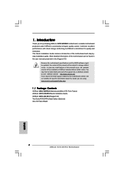
... in the user manual presented in the Support CD. In case any modifications of the motherboard can be available on ASRock website as well. www.asrock.com/support/index.asp 1.1 Package Contents ASRock G41C-GS R2.0 Motherboard (Micro ATX Form Factor) ASRock G41C-GS R2.0 Quick Installation Guide ASRock G41C-GS R2.0 Support CD Two Serial ATA (SATA) Data Cables (Optional) One I/O Panel Shield 4 ASRock G41C-GS R2.0 Motherboard English ASRock website http://www.asrock.com If you are using. You may find the latest VGA cards and CPU support lists on ASRock website...
... in the user manual presented in the Support CD. In case any modifications of the motherboard can be available on ASRock website as well. www.asrock.com/support/index.asp 1.1 Package Contents ASRock G41C-GS R2.0 Motherboard (Micro ATX Form Factor) ASRock G41C-GS R2.0 Quick Installation Guide ASRock G41C-GS R2.0 Support CD Two Serial ATA (SATA) Data Cables (Optional) One I/O Panel Shield 4 ASRock G41C-GS R2.0 Motherboard English ASRock website http://www.asrock.com If you are using. You may find the latest VGA cards and CPU support lists on ASRock website...
Quick Installation Guide
Page 6
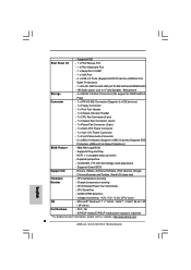
... Voltage multi-adjustment - CPU temperature sensing Monitor - FCC, CE - ErP/EuP ready (ErP/EuP ready power supply is required) * For detailed product information, please visit our website: http://www.asrock.com English 6 ASRock G41C-GS R2.0 Motherboard HD Audio Jacks: Line in / Front Speaker / Microphone Storage - 4 x SATA2 3.0 Gb/s Connectors (No support for RAID and Hot Plug) Connector - 1 x ATA100 IDE Connector (Supports 2 x IDE devices) - 1 x Floppy Connector - 1 x Print Port Header - 1 x Chassis Intrusion Header - 1 x CPU Fan Connector (4-pin) - 1 x Chassis Fan...
... Voltage multi-adjustment - CPU temperature sensing Monitor - FCC, CE - ErP/EuP ready (ErP/EuP ready power supply is required) * For detailed product information, please visit our website: http://www.asrock.com English 6 ASRock G41C-GS R2.0 Motherboard HD Audio Jacks: Line in / Front Speaker / Microphone Storage - 4 x SATA2 3.0 Gb/s Connectors (No support for RAID and Hot Plug) Connector - 1 x ATA100 IDE Connector (Supports 2 x IDE devices) - 1 x Floppy Connector - 1 x Print Port Header - 1 x Chassis Intrusion Header - 1 x CPU Fan Connector (4-pin) - 1 x Chassis Fan...
Quick Installation Guide
Page 10
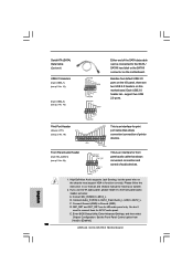
...'97 audio panel. You don't need to [Enabled]. 10 ASRock G41C-GS R2.0 Motherboard English Besides four default USB 2.0 ports on this motherboard. Connect Audio_R (RIN) to OUT2_R and Audio_L (LIN) to install your system. 2. Enter Advanced Settings, and then select Chipset Configuration. Each USB 2.0 header can be connected to the SATA / SATAII hard disk or the SATAII connector on the chassis must support HDA to MIC2_L. Please follow the instruction in our manual and chassis manual to OUT2_L. Serial ATA (SATA) Data Cable (Optional) USB 2.0 Headers (9-pin...
...'97 audio panel. You don't need to [Enabled]. 10 ASRock G41C-GS R2.0 Motherboard English Besides four default USB 2.0 ports on this motherboard. Connect Audio_R (RIN) to OUT2_R and Audio_L (LIN) to install your system. 2. Enter Advanced Settings, and then select Chipset Configuration. Each USB 2.0 header can be connected to the SATA / SATAII hard disk or the SATAII connector on the chassis must support HDA to MIC2_L. Please follow the instruction in our manual and chassis manual to OUT2_L. Serial ATA (SATA) Data Cable (Optional) USB 2.0 Headers (9-pin...

Quick Installation Guide
Page 11
...RESET# GND HDLEDHDLED+ 1 SPEAKER DUMMY DUMMY +5V This header accommodates several system front panel functions. Please connect the chassis speaker to this motherboard provides 4-Pin CPU fan (Quiet Fan) support, the 3-Pin CPU fan still can still work successfully even without the fan speed control function. To use the 20-pin ATX power supply, please plug your power supply along with Pin 1 and Pin 13. 24 13 20-Pin ATX Power Supply Installation 12 1 English 11 ASRock G41C-GS R2.0 Motherboard System Panel Header (9-pin PANEL1) (see p.2 No. 17) Chassis Speaker Header (4-pin SPEAKER...
...RESET# GND HDLEDHDLED+ 1 SPEAKER DUMMY DUMMY +5V This header accommodates several system front panel functions. Please connect the chassis speaker to this motherboard provides 4-Pin CPU fan (Quiet Fan) support, the 3-Pin CPU fan still can still work successfully even without the fan speed control function. To use the 20-pin ATX power supply, please plug your power supply along with Pin 1 and Pin 13. 24 13 20-Pin ATX Power Supply Installation 12 1 English 11 ASRock G41C-GS R2.0 Motherboard System Panel Header (9-pin PANEL1) (see p.2 No. 17) Chassis Speaker Header (4-pin SPEAKER...
Quick Installation Guide
Page 12
... motherboard contains necessary drivers and useful utilities that detects if the chassis cover has been removed. For the detailed information about BIOS Setup, please refer to enter BIOS Setup after POST, please restart the system by pressing + + , or pressing the reset button on the system chassis. The BIOS Setup program is necessary to connect a power supply with chassis intrusion detection design. 2. When you wish to the User Manual (PDF file) contained in your CDROM drive. ATX 12V Connector (4-pin...
... motherboard contains necessary drivers and useful utilities that detects if the chassis cover has been removed. For the detailed information about BIOS Setup, please refer to enter BIOS Setup after POST, please restart the system by pressing + + , or pressing the reset button on the system chassis. The BIOS Setup program is necessary to connect a power supply with chassis intrusion detection design. 2. When you wish to the User Manual (PDF file) contained in your CDROM drive. ATX 12V Connector (4-pin...


