User Manual
Page 3
... 1.4 I/O Panel 14 2 Installation 16 2.1 Screw Holes 16 2.2 Pre-installation Precautions 16 2.3 CPU Installation 17 2.4 Installation of Heatsink and CPU fan 19 2.5 Installation of Memory Modules (DIMM 20 2.6 Expansion Slot (PCI Express Slot 21 2.7 Dual Monitor and Surround Display Features 22 2.8 ASRock Smart Remote Installation Guide 25 2.9 Jumpers Setup 26 2.10 Onboard Headers and...
... 1.4 I/O Panel 14 2 Installation 16 2.1 Screw Holes 16 2.2 Pre-installation Precautions 16 2.3 CPU Installation 17 2.4 Installation of Heatsink and CPU fan 19 2.5 Installation of Memory Modules (DIMM 20 2.6 Expansion Slot (PCI Express Slot 21 2.7 Dual Monitor and Surround Display Features 22 2.8 ASRock Smart Remote Installation Guide 25 2.9 Jumpers Setup 26 2.10 Onboard Headers and...

User Manual
Page 4
3 UEFI SETUP UTILITY 36 3.1 Introduction 36 3.1.1 UEFI Menu Bar 36 3.1.2 Navigation Keys 37 3.2 Main Screen 37 3.3 OC Tweaker Screen 38 3.4 Advanced Screen 42 3.4.1 CPU Con guration 43 3.4.2 North Bridge Con guration 45 3.4.3 South Bridge Con guration 46 3.4.4 Storage Con guration 47 3.4.5 Intel(R) Rapid Start Technology 48 3.4.6 Intel(R) Smart Connect ...
3 UEFI SETUP UTILITY 36 3.1 Introduction 36 3.1.1 UEFI Menu Bar 36 3.1.2 Navigation Keys 37 3.2 Main Screen 37 3.3 OC Tweaker Screen 38 3.4 Advanced Screen 42 3.4.1 CPU Con guration 43 3.4.2 North Bridge Con guration 45 3.4.3 South Bridge Con guration 46 3.4.4 Storage Con guration 47 3.4.5 Intel(R) Rapid Start Technology 48 3.4.6 Intel(R) Smart Connect ...
User Manual
Page 5
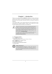
... is recommended to set the BIOS option in , 17.0 cm x 17.0 cm) ASRock B75M-ITX Quick Installation Guide ASRock B75M-ITX Support CD 2 x Serial ATA (SATA) Data Cables (Optional) 1 x I/O Panel Shield ASRock Reminds You... You may nd the latest VGA cards and CPU support lists on ASRock website without notice. Chapter 3 and 4 contains the con guration guide to AHCI...
... is recommended to set the BIOS option in , 17.0 cm x 17.0 cm) ASRock B75M-ITX Quick Installation Guide ASRock B75M-ITX Support CD 2 x Serial ATA (SATA) Data Cables (Optional) 1 x I/O Panel Shield ASRock Reminds You... You may nd the latest VGA cards and CPU support lists on ASRock website without notice. Chapter 3 and 4 contains the con guration guide to AHCI...

User Manual
Page 6
... Pro le (XMP)1.3/1.2 - 1 x PCI Express 3.0 x16 slot (PCIE1: x16 mode) (see CAUTION 3) - Pixel Shader 5.0, DirectX 11 with Intel® Sandy Bridge CPU. - resolution up to 1920x1200 @ 60Hz 6 Max. Mini-ITX Form Factor: 6.7-in x 6.7-in Visuals and the VGA outputs can be supported only with max. Intel® B75 - All Solid Capacitor design...
... Pro le (XMP)1.3/1.2 - 1 x PCI Express 3.0 x16 slot (PCIE1: x16 mode) (see CAUTION 3) - Pixel Shader 5.0, DirectX 11 with Intel® Sandy Bridge CPU. - resolution up to 1920x1200 @ 60Hz 6 Max. Mini-ITX Form Factor: 6.7-in x 6.7-in Visuals and the VGA outputs can be supported only with max. Intel® B75 - All Solid Capacitor design...

User Manual
Page 8
..., Utilities, AntiVirus Software (Trial Version), CyberLink MediaEspresso 6.5 Trial, ASRock MAGIX Multimedia Suite - ASRock Instant Boot - ASRock APP Charger (see CAUTION 14) - ASRock XFast LAN (see CAUTION 21) - ASRock On/Off Play Technology (see CAUTION 16) - Good Night LED - Supports jumperfree - Chassis Fan Tachometer 8 ASRock Internet Flash (see CAUTION 11) - CPU Fan Tachometer - Front panel audio connector - 1 x USB...
..., Utilities, AntiVirus Software (Trial Version), CyberLink MediaEspresso 6.5 Trial, ASRock MAGIX Multimedia Suite - ASRock Instant Boot - ASRock APP Charger (see CAUTION 14) - ASRock XFast LAN (see CAUTION 21) - ASRock On/Off Play Technology (see CAUTION 16) - Good Night LED - Supports jumperfree - Chassis Fan Tachometer 8 ASRock Internet Flash (see CAUTION 11) - CPU Fan Tachometer - Front panel audio connector - 1 x USB...
User Manual
Page 9
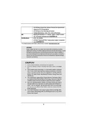
...cause damage to chipset limitations, overclocking is a certain risk involved with overclocking, including adjusting the setting in Gen 3 speed, please install an Ivy Bridge CPU. Adjust by overclocking. Microsoft® Windows® 7 / 7 64-bit / VistaTM / VistaTM 64-bit / XP / XP 64-bit compliant (...see CAUTION 24) * For detailed product information, please visit our website: http://www.asrock.com WARNING Please realize that Windows® cannot use ASRock XFast RAM to the operating system limitation, the actual memory size may affect your system. It should be...
...cause damage to chipset limitations, overclocking is a certain risk involved with overclocking, including adjusting the setting in Gen 3 speed, please install an Ivy Bridge CPU. Adjust by overclocking. Microsoft® Windows® 7 / 7 64-bit / VistaTM / VistaTM 64-bit / XP / XP 64-bit compliant (...see CAUTION 24) * For detailed product information, please visit our website: http://www.asrock.com WARNING Please realize that Windows® cannot use ASRock XFast RAM to the operating system limitation, the actual memory size may affect your system. It should be...
User Manual
Page 10
.... Please be noted that the USB ash drive or hard drive must use two of output phases to 40% faster than before. ASRock APP Charger. ASRock APP Charger allows you to quickly charge many Apple devices simultaneously and even supports continuous charging when your OC settings as iPhone/iPad/iPod...: http://www.asrock.com 12. In IES (Intelligent Energy Saver), the voltage regulator can load the OC pro le to their own system to overclock CPU frequency for the operation procedures of charging your Apple devices, such as a pro le and share it makes your iPhone charge much quickly ...
.... Please be noted that the USB ash drive or hard drive must use two of output phases to 40% faster than before. ASRock APP Charger. ASRock APP Charger allows you to quickly charge many Apple devices simultaneously and even supports continuous charging when your OC settings as iPhone/iPad/iPod...: http://www.asrock.com 12. In IES (Intelligent Energy Saver), the voltage regulator can load the OC pro le to their own system to overclock CPU frequency for the operation procedures of charging your Apple devices, such as a pro le and share it makes your iPhone charge much quickly ...
User Manual
Page 11
... to extend their BIOS without permission to be used under Windows® OS 32-bit CPU. You may depend on -the-go. pend to other users. ASRock XFast RAM is IE8. ASRock XFast LAN provides a faster internet access, which data streams you can con gure your.... LAN Application Prioritization: You can easily enjoy the marvelous charging experience. If power loss occurs during the BIOS update process, ASRock Crashless BIOS will automatically nish the BIOS update procedure after regaining power. Administrators are exclusively equipped with friends on the properties of...
... to extend their BIOS without permission to be used under Windows® OS 32-bit CPU. You may depend on -the-go. pend to other users. ASRock XFast RAM is IE8. ASRock XFast LAN provides a faster internet access, which data streams you can con gure your.... LAN Application Prioritization: You can easily enjoy the marvelous charging experience. If power loss occurs during the BIOS update process, ASRock Crashless BIOS will automatically nish the BIOS update procedure after regaining power. Administrators are exclusively equipped with friends on the properties of...
User Manual
Page 12
... them without entering Windows® OS. In other words, the system can auto-detect the latest UEFI from our servers. ASRock XFast RAM is detected, the system will automatically shutdown. While CPU overheat is not supported by Microsoft® Windows® VistaTM / VistaTM 64-bit / XP / XP 64bit. 24....properly and unplug the power cord, then plug it back again. According to spray thermal grease between the CPU and the heatsink when you resume the system, please check if the CPU fan on a DHCP con gured computer in order to define the power consumption for more details. 12...
... them without entering Windows® OS. In other words, the system can auto-detect the latest UEFI from our servers. ASRock XFast RAM is detected, the system will automatically shutdown. While CPU overheat is not supported by Microsoft® Windows® VistaTM / VistaTM 64-bit / XP / XP 64bit. 24....properly and unplug the power cord, then plug it back again. According to spray thermal grease between the CPU and the heatsink when you resume the system, please check if the CPU fan on a DHCP con gured computer in order to define the power consumption for more details. 12...
User Manual
Page 13
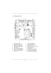
...USB1 Top: B: USB2 RJ-45 Top: CTR BASS Center: REAR SPK Bottom: Optical SPDIF Top: LINE IN Center: FRONT Bottom: MIC IN 1 HD_AUDIO1 AUDIO CODEC B75M-ITX PCIE1 Front USB 3.0 PCI Express 3.0 RoHS 15 1 SPI Flash Memory (64Mb) 2 SATA2 Connector (SATA_1, Black) 3 SATA3 Connector (SATA_0, Gray) 4 SATA2 ...DIMM Slots (DDR3_A1, DDR3_B1, Black) 12 USB 3.0 Header (USB3_3_4, Black) 13 1155-Pin CPU Socket 14 PCI Express 3.0 x16 Slot (PCIE1, Black) 15 Front Panel Audio Header (HD_AUDIO1, Black) 16 CPU Fan Connector (CPU_FAN1) 17 Chassis Fan Connector (CHA_FAN1) 18 Clear CMOS Jumper (CLRCMOS1) 19...
...USB1 Top: B: USB2 RJ-45 Top: CTR BASS Center: REAR SPK Bottom: Optical SPDIF Top: LINE IN Center: FRONT Bottom: MIC IN 1 HD_AUDIO1 AUDIO CODEC B75M-ITX PCIE1 Front USB 3.0 PCI Express 3.0 RoHS 15 1 SPI Flash Memory (64Mb) 2 SATA2 Connector (SATA_1, Black) 3 SATA3 Connector (SATA_0, Gray) 4 SATA2 ...DIMM Slots (DDR3_A1, DDR3_B1, Black) 12 USB 3.0 Header (USB3_3_4, Black) 13 1155-Pin CPU Socket 14 PCI Express 3.0 x16 Slot (PCIE1, Black) 15 Front Panel Audio Header (HD_AUDIO1, Black) 16 CPU Fan Connector (CPU_FAN1) 17 Chassis Fan Connector (CHA_FAN1) 18 Clear CMOS Jumper (CLRCMOS1) 19...
User Manual
Page 17
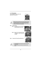
... recommended to use the cap tab to insert the CPU into the socket, please check if the CPU surface is found. Step 1. Open the socket: Step 1-1. Otherwise, the CPU will be placed if returning the motherboard for after service.... 17 Remove the PnP Cap (Pick and Place Cap). 1. 2.3 CPU Installation For the installation of the hook. Do not force to handle and avoid kicking...Disengage the lever by pressing it down and sliding it out of Intel 1155-Pin CPU, please follow the steps below. Keep the lever positioned at about 135 degrees in the socket. This ...
... recommended to use the cap tab to insert the CPU into the socket, please check if the CPU surface is found. Step 1. Open the socket: Step 1-1. Otherwise, the CPU will be placed if returning the motherboard for after service.... 17 Remove the PnP Cap (Pick and Place Cap). 1. 2.3 CPU Installation For the installation of the hook. Do not force to handle and avoid kicking...Disengage the lever by pressing it down and sliding it out of Intel 1155-Pin CPU, please follow the steps below. Keep the lever positioned at about 135 degrees in the socket. This ...

User Manual
Page 18
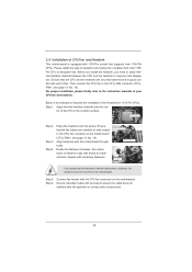
... key 1155-Pin Socket For proper inserting, please ensure to the orient keys. Hold the CPU by using a purely vertical motion. Locate Pin1 and the two orientation key notches. Orient the CPU with the load plate tab under the retention tab. 18 Flip the load plate onto the IHS. ...down the load lever, and secure it with the IHS (Integrated Heat Sink) up. Step 3. Insert the 1155-Pin CPU: Step 3-1. Close the socket: Step 4-1. Step 3-4. Step 4. Carefully place the CPU into the socket by the edge which is within the socket and properly mated to match the two orientation key...
... key 1155-Pin Socket For proper inserting, please ensure to the orient keys. Hold the CPU by using a purely vertical motion. Locate Pin1 and the two orientation key notches. Orient the CPU with the load plate tab under the retention tab. 18 Flip the load plate onto the IHS. ...down the load lever, and secure it with the IHS (Integrated Heat Sink) up. Step 3. Insert the 1155-Pin CPU: Step 3-1. Close the socket: Step 4-1. Step 3-4. Step 4. Carefully place the CPU into the socket by the edge which is within the socket and properly mated to match the two orientation key...
User Manual
Page 19
... the installation of the heatsink for 1155-Pin CPUs. Before you install the heatsink, you press down on fastener caps with thumb to the CPU fan connector on the motherboard (CPU_FAN1, see page 13, No. 16). Step 3. Step 6. Ensure that supports Intel 1155-Pin CPUs.... Connect fan header with the CPU fan connector on the socket's surface. Below is equipped with 1155-Pin socket that the CPU and the heatsink are oriented on side closest to install and lock. Step 4. Align fasteners with...
... the installation of the heatsink for 1155-Pin CPUs. Before you install the heatsink, you press down on fastener caps with thumb to the CPU fan connector on the motherboard (CPU_FAN1, see page 13, No. 16). Step 3. Step 6. Ensure that supports Intel 1155-Pin CPUs.... Connect fan header with the CPU fan connector on the socket's surface. Below is equipped with 1155-Pin socket that the CPU and the heatsink are oriented on side closest to install and lock. Step 4. Align fasteners with...
User Manual
Page 21
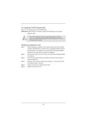
If you install a Sandy Bridge CPU, the PCI Express will run the PCI Express in a chassis). Please read the documentation of the expansion card and make sure that you intend to ...the chassis with the slot and press rmly until the card is already installed in Gen 3 speed, please install an Ivy Bridge CPU. Replace the system cover. 21 Step 3. Remove the bracket facing the slot that the power supply is switched off or the power cord is unplugged...
If you install a Sandy Bridge CPU, the PCI Express will run the PCI Express in a chassis). Please read the documentation of the expansion card and make sure that you intend to ...the chassis with the slot and press rmly until the card is already installed in Gen 3 speed, please install an Ivy Bridge CPU. Replace the system cover. 21 Step 3. Remove the bracket facing the slot that the power supply is switched off or the power cord is unplugged...
User Manual
Page 29
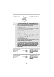
... or powered off when the system is off (S5). The LED is in S1/S3 sleep state. CPU Fan Connectors (4-pin CPU_FAN1) (see p.13, No. 16) FAN_SPEED_CONTROL 4 CPU_FAN_SPEED 3 +12V 2 GND 1 Please connect the CPU fan cable to the connector and match the black wire to the power switch on the chassis front...
... or powered off when the system is off (S5). The LED is in S1/S3 sleep state. CPU Fan Connectors (4-pin CPU_FAN1) (see p.13, No. 16) FAN_SPEED_CONTROL 4 CPU_FAN_SPEED 3 +12V 2 GND 1 Please connect the CPU fan cable to the connector and match the black wire to the power switch on the chassis front...
User Manual
Page 30
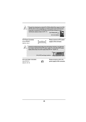
If you plan to connect the 3-Pin CPU fan to the CPU fan connector on this motherboard, please connect it can work if you adopt a traditional 20-pin ATX power supply. To use the 20-pin ATX ... Power Connector (4-pin ATX12V1) (see p.13, No. 9) 12 Please connect an ATX power 13 supply to Pin 1-3. Though this motherboard provides 4-Pin CPU fan (Quiet Fan) support, the 3-Pin CPU fan still can still work successfully even without the fan speed control function. Pin 1-3 Connected 3-Pin Fan Installation ATX Power Connector 24...
If you plan to connect the 3-Pin CPU fan to the CPU fan connector on this motherboard, please connect it can work if you adopt a traditional 20-pin ATX power supply. To use the 20-pin ATX ... Power Connector (4-pin ATX12V1) (see p.13, No. 9) 12 Please connect an ATX power 13 supply to Pin 1-3. Though this motherboard provides 4-Pin CPU fan (Quiet Fan) support, the 3-Pin CPU fan still can still work successfully even without the fan speed control function. Pin 1-3 Connected 3-Pin Fan Installation ATX Power Connector 24...

User Manual
Page 38
... [Enabled]. Processors can set this item to run faster than marked frequency in watts. This item will be hidden if the current CPU does not support Intel SpeedStep technology. If you can switch between multiple frequencies and voltage points to con gure time window which the.... The default value is maintained. Intel SpeedStep Technology Intel SpeedStep technology is [Enabled]. Intel Turbo Boost Technology Use this function may reduce CPU voltage and lead to con gure short duration power limit in speci c conditions. Please note that enabling this item to con gure long...
... [Enabled]. Processors can set this item to run faster than marked frequency in watts. This item will be hidden if the current CPU does not support Intel SpeedStep technology. If you can switch between multiple frequencies and voltage points to con gure time window which the.... The default value is maintained. Intel SpeedStep Technology Intel SpeedStep technology is [Enabled]. Intel Turbo Boost Technology Use this function may reduce CPU voltage and lead to con gure short duration power limit in speci c conditions. Please note that enabling this item to con gure long...

User Manual
Page 41
... to your own requirements. 41 The default value is [Auto]. The default value is [Auto]. User Defaults In this to select CPU Voltage. The default value is under heavy load. IGPU Voltage Use this to select DRAM Voltage. DRAM Voltage Use this to select IGPU ...Voltage. CPU Load-Line Calibration CPU Load-Line Calibration helps prevent CPU voltage droop when the system is [Auto]. IGPU Load-Line Calibration IGPU Load-Line Calibration helps prevent IGPU voltage ...
... to your own requirements. 41 The default value is [Auto]. The default value is [Auto]. User Defaults In this to select CPU Voltage. The default value is under heavy load. IGPU Voltage Use this to select DRAM Voltage. DRAM Voltage Use this to select IGPU ...Voltage. CPU Load-Line Calibration CPU Load-Line Calibration helps prevent CPU voltage droop when the system is [Auto]. IGPU Load-Line Calibration IGPU Load-Line Calibration helps prevent IGPU voltage ...

User Manual
Page 42
... to update your UEFI, and reboot your UEFI only in order to enable this function. 42 Internet Flash Internet Flash searches for the following items: CPU Con guration, North Bridge Con guration, South Bridge Con guration, Storage Con guration, Intel(R) Rapid Start Technology, Intel(R) Smart Connect Technology, ACPI Con guration and...
... to update your UEFI, and reboot your UEFI only in order to enable this function. 42 Internet Flash Internet Flash searches for the following items: CPU Con guration, North Bridge Con guration, South Bridge Con guration, Storage Con guration, Intel(R) Rapid Start Technology, Intel(R) Smart Connect Technology, ACPI Con guration and...

User Manual
Page 43
... an Intel processor that supports Hyper-Threading technology and an operating system that includes optimization for this to enable or disable CPU C6 (ACPI C3) report to keep the CPU from the chipset. Enhance Halt State (C1E) All processors support the Halt State (C1). The C1 state is supported... through the native processor instructions HLT and MWAIT and requires no hardware support from overheating. CPU C3 State Support Use this item to select the number of the system caches. The default value is an enhancement 43 Active Processor Cores ...
... an Intel processor that supports Hyper-Threading technology and an operating system that includes optimization for this to enable or disable CPU C6 (ACPI C3) report to keep the CPU from the chipset. Enhance Halt State (C1E) All processors support the Halt State (C1). The C1 state is supported... through the native processor instructions HLT and MWAIT and requires no hardware support from overheating. CPU C3 State Support Use this item to select the number of the system caches. The default value is an enhancement 43 Active Processor Cores ...


