Software/BIOS Setup Guide
Page 3
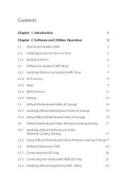
... 6 2.2 ASRock Live Update & APP Shop 7 2.2.1 Installing ASRock Live Update & APP Shop 7 2.2.2 UI Overview 8 2.2.3 Apps 9 2.2.4 BIOS & Drivers 12 2.2.5 Setting 13 2.3 ASRock Motherboard Utility (A-Tuning) 14 2.3.1 Installing ASRock Motherboard Utility (A-Tuning) 14 2.3.2 Using ASRock Motherboard Utility (A-Tuning) 14 2.4 ASRock Motherboard Utility (Phantom Gaming Tuning) 17 2.4.1 Installing ASRock Motherboard Utility (Phantom Gaming Tuning) 17 2.4.2 Using ASRock Motherboard Utility (Phantom Gaming Tuning)17 2.5 ASRock Polychrome SYNC 20 2.5.1 Connecting the LED Strip...
... 6 2.2 ASRock Live Update & APP Shop 7 2.2.1 Installing ASRock Live Update & APP Shop 7 2.2.2 UI Overview 8 2.2.3 Apps 9 2.2.4 BIOS & Drivers 12 2.2.5 Setting 13 2.3 ASRock Motherboard Utility (A-Tuning) 14 2.3.1 Installing ASRock Motherboard Utility (A-Tuning) 14 2.3.2 Using ASRock Motherboard Utility (A-Tuning) 14 2.4 ASRock Motherboard Utility (Phantom Gaming Tuning) 17 2.4.1 Installing ASRock Motherboard Utility (Phantom Gaming Tuning) 17 2.4.2 Using ASRock Motherboard Utility (Phantom Gaming Tuning)17 2.5 ASRock Polychrome SYNC 20 2.5.1 Connecting the LED Strip...
Software/BIOS Setup Guide
Page 5
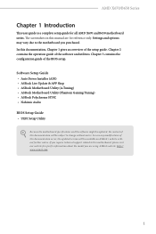
... case any modifications of this motherboard, please visit our website for specific information about the model you are for all AMD X670 and B650 motherboard series. If you purchased. ASRock website http:// www.asrock.com. 1 In this manual are using. Software Setup Guide • Auto Driver Installer (ADI) • ASRock Live Update & APP Shop • ASRock Motherboard Utility (A-Tuning) • ASRock Motherboard Utility (Phantom Gaming Tuning) • ASRock Polychrome SYNC • Nahimic Audio BIOS Setup Guide • UEFI Setup Utility Because the motherboard specifications and...
... case any modifications of this motherboard, please visit our website for specific information about the model you are for all AMD X670 and B650 motherboard series. If you purchased. ASRock website http:// www.asrock.com. 1 In this manual are using. Software Setup Guide • Auto Driver Installer (ADI) • ASRock Live Update & APP Shop • ASRock Motherboard Utility (A-Tuning) • ASRock Motherboard Utility (Phantom Gaming Tuning) • ASRock Polychrome SYNC • Nahimic Audio BIOS Setup Guide • UEFI Setup Utility Because the motherboard specifications and...
Software/BIOS Setup Guide
Page 7
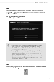
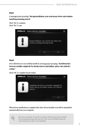
..., for using the Auto Driver Installer. Now connect your screen saying, "Do you want to one-step-install the latest drivers simply from ASRock Auto Driver Installer?". The item is no need to change the setting in the BIOS. 2. If you select "No" in Step 2 and skip the installation, the Auto Driver Installer will be removed. Select "No" to install Auto Driver Installer. If you would like to run the application again, please enable the "Auto Driver Installer...
..., for using the Auto Driver Installer. Now connect your screen saying, "Do you want to one-step-install the latest drivers simply from ASRock Auto Driver Installer?". The item is no need to change the setting in the BIOS. 2. If you select "No" in Step 2 and skip the installation, the Auto Driver Installer will be removed. Select "No" to install Auto Driver Installer. If you would like to run the application again, please enable the "Auto Driver Installer...
Software/BIOS Setup Guide
Page 9
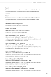
..." menu in the BIOS setting, and set the "Auto Driver Installer" item to complete the procedure. For further drivers and utilities, please visit ASRock's website." Click "Ok" to [Enabled]. 5 Step 6 Once all drivers are successfully installed, a message pops up saying, "During installation, your computer. When driver installation is completed, the Auto Driver Installer tool will be uninstalled automatically from your system may reboot and continue installing remaining item(s)". AMD X670/B650 Series...
..." menu in the BIOS setting, and set the "Auto Driver Installer" item to complete the procedure. For further drivers and utilities, please visit ASRock's website." Click "Ok" to [Enabled]. 5 Step 6 Once all drivers are successfully installed, a message pops up saying, "During installation, your computer. When driver installation is completed, the Auto Driver Installer tool will be uninstalled automatically from your system may reboot and continue installing remaining item(s)". AMD X670/B650 Series...

Software/BIOS Setup Guide
Page 29
AMD X670/B650 Series Chapter 3 UEFI SETUP UTILITY 3.1 Introduction ASRock UEFI (Unified Extensible Firmware Interface) is turned off and then back on. If the system becomes unstable or fails to default values. See your motherboard manual for instructions. 3.1.1 Entering BIOS Setup You may also restart by pressing or right after you do not alter the UEFI default configurations or change the setting, try to clear the CMOS values and reset the board to boot after POST, restart the...
AMD X670/B650 Series Chapter 3 UEFI SETUP UTILITY 3.1 Introduction ASRock UEFI (Unified Extensible Firmware Interface) is turned off and then back on. If the system becomes unstable or fails to default values. See your motherboard manual for instructions. 3.1.1 Entering BIOS Setup You may also restart by pressing or right after you do not alter the UEFI default configurations or change the setting, try to clear the CMOS values and reset the board to boot after POST, restart the...
Software/BIOS Setup Guide
Page 37
... enable or disable DDR5 power down mode. Power Down Enable Allows you to specify the Dram ODT impedance RTT_NOM_WR. Configuration options: [Auto] [RTT_OFF] [RZQ (240)] [RZQ/2 (120)] [RZQ/3 (80)] 33 Trdwr The minimum number of cycles from the last clock of virtual CAS of the first readburst operation to the clock in which CAS is asserted for a following read-burst operation. AMD X670/B650 Series...
... enable or disable DDR5 power down mode. Power Down Enable Allows you to specify the Dram ODT impedance RTT_NOM_WR. Configuration options: [Auto] [RTT_OFF] [RZQ (240)] [RZQ/2 (120)] [RZQ/3 (80)] 33 Trdwr The minimum number of cycles from the last clock of virtual CAS of the first readburst operation to the clock in which CAS is asserted for a following read-burst operation. AMD X670/B650 Series...
Software/BIOS Setup Guide
Page 48
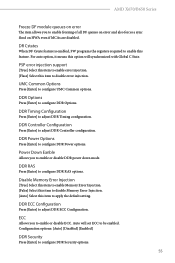
...Low Frequency Peak Port B Allows you to configure the Downstream High Frequency Peak Port A settings. Configure the size of memory that is allocated to the integrated graphics processor when the system boots up. [Auto] BIOS will configure this option to configure the Downstream Low Frequency Peak Port B settings. Downstream Low Frequency Peak Port A Allows you to Auto. Upstream High Frequency Peak Port A Allows you to configure the Upstream High Frequency Peak Port A settings. 44 Onboard HD Audio Allows you to enable or disable onboard HD audio. Downstream High Frequency Peak...
...Low Frequency Peak Port B Allows you to configure the Downstream High Frequency Peak Port A settings. Configure the size of memory that is allocated to the integrated graphics processor when the system boots up. [Auto] BIOS will configure this option to configure the Downstream Low Frequency Peak Port B settings. Downstream Low Frequency Peak Port A Allows you to Auto. Upstream High Frequency Peak Port A Allows you to configure the Upstream High Frequency Peak Port A settings. 44 Onboard HD Audio Allows you to enable or disable onboard HD audio. Downstream High Frequency Peak...
Software/BIOS Setup Guide
Page 57
... selection for analysis purposes as long as default. [Disabled] This can be set to zero for this option is enabled, uncorrected errors detected by default (Auto), the Bronze workaround is set to 1 as OS supports it . Configuration options: [Auto] [Disabled] [Enabled] Fast Short REP MOVSB [Enabled] This is only applicable for analysis purposes as long as default. [Disabled] This can be set to enable or disable the PPIN feature. Configuration options: [Disabled] [Enabled] Power Supply Idle Control Allows you to determine...
... selection for analysis purposes as long as default. [Disabled] This can be set to zero for this option is enabled, uncorrected errors detected by default (Auto), the Bronze workaround is set to 1 as OS supports it . Configuration options: [Auto] [Disabled] [Enabled] Fast Short REP MOVSB [Enabled] This is only applicable for analysis purposes as long as default. [Disabled] This can be set to enable or disable the PPIN feature. Configuration options: [Disabled] [Enabled] Power Supply Idle Control Allows you to determine...
Software/BIOS Setup Guide
Page 59
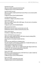
... enable Memory Error Injection. [False] Select this item to disable Memory Error Injection. [Auto] Select this item to apply the default setting. PSP error injection support [True] Select this item to enable error injection. [Flase] Select this item to disable error injection. DDR Timing Configuration Press [Enter] to configure DDR Options. Configuration options: [Auto] [Disabled] [Enabled] DDR Security Press [Enter] to configure UMC Common options. For auto option, it means this feature. UMC Common Options Press [Enter] to configure DDR Security options. 55 Power...
... enable Memory Error Injection. [False] Select this item to disable Memory Error Injection. [Auto] Select this item to apply the default setting. PSP error injection support [True] Select this item to enable error injection. [Flase] Select this item to disable error injection. DDR Timing Configuration Press [Enter] to configure DDR Options. Configuration options: [Auto] [Disabled] [Enabled] DDR Security Press [Enter] to configure UMC Common options. For auto option, it means this feature. UMC Common Options Press [Enter] to configure DDR Security options. 55 Power...
Software/BIOS Setup Guide
Page 65
Configuration options: [Auto] [Disabled] [Enabled] SyncFifo Mode Override Allows you to enable or disable FEATURE FCLK DPM. Configuration options: [Auto] [Disabled] [Enabled] Soc Miscellaneous Control Press [Enter] to HSP commands. no further PSP to configure Soc Miscellaneous Control. Pluton (HSP) UART HSP Firmware will print debug information to configure Pluton (HSP) Options. When it will gate the HSP clock; This option will boot without HSP. By default, it is set up PSP directiry entry OxB, BIT36...
Configuration options: [Auto] [Disabled] [Enabled] SyncFifo Mode Override Allows you to enable or disable FEATURE FCLK DPM. Configuration options: [Auto] [Disabled] [Enabled] Soc Miscellaneous Control Press [Enter] to HSP commands. no further PSP to configure Soc Miscellaneous Control. Pluton (HSP) UART HSP Firmware will print debug information to configure Pluton (HSP) Options. When it will gate the HSP clock; This option will boot without HSP. By default, it is set up PSP directiry entry OxB, BIT36...

Software/BIOS Setup Guide
Page 68
..., GPP1-CPU] Note: Switch APU clocks source mapping will get stuck immediately (post code: B0005A5A). Manully press cold reset button to the RAID configuration. External CLK Control Allows you to enable or disable NVMe RAID mode. Configuration options: [Auto] [Gen1]-[Gen5] Chipset Link Speed Allows you to configure M.2_1 Link Speed. Please set the "PCIe/GFX Lanes Configuration" item according to bypass the stuck. Configuration options: [Auto] [Gen1]-[Gen5] M.2_1 Link Speed Allows you to configure Chipset Link Speed. Configuration options: [Disabled] [Enabled] Adjust...
..., GPP1-CPU] Note: Switch APU clocks source mapping will get stuck immediately (post code: B0005A5A). Manully press cold reset button to the RAID configuration. External CLK Control Allows you to enable or disable NVMe RAID mode. Configuration options: [Auto] [Gen1]-[Gen5] Chipset Link Speed Allows you to configure M.2_1 Link Speed. Please set the "PCIe/GFX Lanes Configuration" item according to bypass the stuck. Configuration options: [Auto] [Gen1]-[Gen5] M.2_1 Link Speed Allows you to configure Chipset Link Speed. Configuration options: [Disabled] [Enabled] Adjust...
Software/BIOS Setup Guide
Page 72
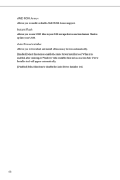
Instant Flash Allows you to save UEFI files in your UEFI. When it is enabled, after entering to Windows with available Internet access, the Auto Driver Installer tool will appear automatically. [Disabled] Select this item to enable or diable AMD ROM Armor support. Auto Driver Installer Allows you to download and install all necessary drivers automatically. [Enabled] Select this item to update your USB storage device and run Instant Flash to disable the Auto Driver Installer tool. 68 AMD ROM Armor Allows you to enable the Auto Driver Installer tool.
Instant Flash Allows you to save UEFI files in your UEFI. When it is enabled, after entering to Windows with available Internet access, the Auto Driver Installer tool will appear automatically. [Disabled] Select this item to enable or diable AMD ROM Armor support. Auto Driver Installer Allows you to download and install all necessary drivers automatically. [Enabled] Select this item to update your USB storage device and run Instant Flash to disable the Auto Driver Installer tool. 68 AMD ROM Armor Allows you to enable the Auto Driver Installer tool.
Software/BIOS Setup Guide
Page 80
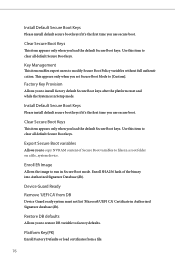
... when you set Secure Boot Mode to install factory default Secure Boot keys after the platform reset and while the System is in a root folder on a file_system device. This appears only when you load the default Secure Boot keys. Device Guard Ready Remove 'UEFI CA' from a file: 76 Use this item to copy NVRAM content of the binary into Authorized Signature Database (db). Key Management This item enables expert users to...
... when you set Secure Boot Mode to install factory default Secure Boot keys after the platform reset and while the System is in a root folder on a file_system device. This appears only when you load the default Secure Boot keys. Device Guard Ready Remove 'UEFI CA' from a file: 76 Use this item to copy NVRAM content of the binary into Authorized Signature Database (db). Key Management This item enables expert users to...

User Manual
Page 3
... Contents 1 1.2 Specifications 2 1.3 Motherboard Layout 6 1.4 I/O Panel 8 1.5 Block Diagram 10 Chapter 2 Installation 11 2.1 Installing the CPU 12 2.2 Installing the CPU Fan and Heatsink 15 2.3 Installing Memory Modules (DIMM) 24 2.4 Connecting the Front Panel Header 26 2.5 Installing the Motherboard 27 2.6 Installing SATA Drives 28 2.7 Installing a Graphics Card 30 2.8 Connecting Peripheral Devices 32 2.9 Connecting the Power Connectors 33 2.10 Power On 34 2.11 Jumpers Setup 35 2.12 Onboard Headers and Connectors 36 2.13 Smart Switches 49 2.14 Post Status...
... Contents 1 1.2 Specifications 2 1.3 Motherboard Layout 6 1.4 I/O Panel 8 1.5 Block Diagram 10 Chapter 2 Installation 11 2.1 Installing the CPU 12 2.2 Installing the CPU Fan and Heatsink 15 2.3 Installing Memory Modules (DIMM) 24 2.4 Connecting the Front Panel Header 26 2.5 Installing the Motherboard 27 2.6 Installing SATA Drives 28 2.7 Installing a Graphics Card 30 2.8 Connecting Peripheral Devices 32 2.9 Connecting the Power Connectors 33 2.10 Power On 34 2.11 Jumpers Setup 35 2.12 Onboard Headers and Connectors 36 2.13 Smart Switches 49 2.14 Post Status...

User Manual
Page 11
... Panel Header (PANEL1) 16 Power LED and Speaker Header (SPK_PLED1) 17 Clear CMOS Jumper (CLRCMOS1) 18 USB 3.2 Gen1 Header (USB32_6_7) 19 Post Status Checker (PSC) 20 Chassis/Water Pump Fan Connector (CHA_FAN3/WP) 21 USB 2.0 Header (USB_5_6) 22 USB 2.0 Header (USB_7_8) 23 Chassis/Water Pump Fan Connector (CHA_FAN2/WP) 24 Chassis/Water Pump Fan Connector (CHA_FAN1/WP) 25 Addressable LED Header (ADDR_LED1) 26 Addressable LED Header (ADDR_LED2) 27 5-pin Thunderbolt AIC Connector (TB1) 28 Front Panel Audio Header (HD_AUDIO1) 29 CPU/Water Pump Fan Connector (CPU_FAN2/WP) B650M PG Riptide...
... Panel Header (PANEL1) 16 Power LED and Speaker Header (SPK_PLED1) 17 Clear CMOS Jumper (CLRCMOS1) 18 USB 3.2 Gen1 Header (USB32_6_7) 19 Post Status Checker (PSC) 20 Chassis/Water Pump Fan Connector (CHA_FAN3/WP) 21 USB 2.0 Header (USB_5_6) 22 USB 2.0 Header (USB_7_8) 23 Chassis/Water Pump Fan Connector (CHA_FAN2/WP) 24 Chassis/Water Pump Fan Connector (CHA_FAN1/WP) 25 Addressable LED Header (ADDR_LED1) 26 Addressable LED Header (ADDR_LED2) 27 5-pin Thunderbolt AIC Connector (TB1) 28 Front Panel Audio Header (HD_AUDIO1) 29 CPU/Water Pump Fan Connector (CPU_FAN2/WP) B650M PG Riptide...

User Manual
Page 35
... hardware settings for PCIe x4 lane width graphics cards. PCIe Slot Configurations Single Graphics Card PCIE1 Gen4x16 PCIE4 N/A Two Graphics Cards in CrossFireTM Mode Gen4x16 Gen4x4 For a better thermal environment, please connect a chassis fan to the motherboard's chassis fan connector (CHA_FAN1~3/WP) when using multiple graphics cards. 31 PCIE3 (PCIe 3.0 x1 slot) is unplugged. B650M PG Riptide Expansion Slots (PCIe Slots) There are 4 PCI Express slots on the motherboard. Please read the documentation of the expansion card and make sure that the power supply is switched off...
... hardware settings for PCIe x4 lane width graphics cards. PCIe Slot Configurations Single Graphics Card PCIE1 Gen4x16 PCIE4 N/A Two Graphics Cards in CrossFireTM Mode Gen4x16 Gen4x4 For a better thermal environment, please connect a chassis fan to the motherboard's chassis fan connector (CHA_FAN1~3/WP) when using multiple graphics cards. 31 PCIE3 (PCIe 3.0 x1 slot) is unplugged. B650M PG Riptide Expansion Slots (PCIe Slots) There are 4 PCI Express slots on the motherboard. Please read the documentation of the expansion card and make sure that the power supply is switched off...

User Manual
Page 54
... the system and remove/ disconnect the CMOS battery from the motherboard for about three seconds. Please make sure the file system of X: USB flash drive. 5. If the recovery key is missing while encryption is not operating properly. Then turn on the system, even without CPU. Otherwise an unpredictable failure may occur. Then the LED starts to power on the TPM. Before using the BIOS Flashback function, please suspend...
... the system and remove/ disconnect the CMOS battery from the motherboard for about three seconds. Please make sure the file system of X: USB flash drive. 5. If the recovery key is missing while encryption is not operating properly. Then turn on the system, even without CPU. Otherwise an unpredictable failure may occur. Then the LED starts to power on the TPM. Before using the BIOS Flashback function, please suspend...
User Manual
Page 56
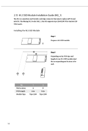
B A No. Nut Location PCB Length Module Type 1 A 6cm Type 2260 2 B 8cm Type 2280 52 Installing the M.2 SSD Module Step 1 Prepare a M.2 SSD module. 2 Step 2 1 Depending on the PCB type and length of your M.2 SSD module, find the corresponding nut location to replace mPCIe and mSATA. The Blazing M.2 Socket (M2_1, Key M) supports type 2260/2280 PCIe Gen5x4 (128 Gb/s) mode. 2.15 M.2 SSD Module Installation Guide (M2_1) The M.2 is a small size and versatile card edge connector that aims to be used.
B A No. Nut Location PCB Length Module Type 1 A 6cm Type 2260 2 B 8cm Type 2280 52 Installing the M.2 SSD Module Step 1 Prepare a M.2 SSD module. 2 Step 2 1 Depending on the PCB type and length of your M.2 SSD module, find the corresponding nut location to replace mPCIe and mSATA. The Blazing M.2 Socket (M2_1, Key M) supports type 2260/2280 PCIe Gen5x4 (128 Gb/s) mode. 2.15 M.2 SSD Module Installation Guide (M2_1) The M.2 is a small size and versatile card edge connector that aims to be used.
User Manual
Page 60
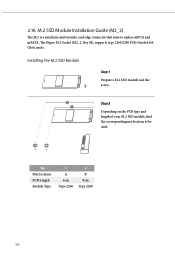
Nut Location PCB Length Module Type 1 A 6cm Type 2260 2 B 8cm Type 2280 56 2.16 M.2 SSD Module Installation Guide (M2_2) The M.2 is a small size and versatile card edge connector that aims to be used. B A No. Installing the M.2 SSD Module Step 1 Prepare a M.2 SSD module and the screw. 2 Step 2 1 Depending on the PCB type and length of your M.2 SSD module, find the corresponding nut location to replace mPCIe and mSATA. The Hyper M.2 Socket (M2_2, Key M), supports type 2260/2280 PCIe Gen4x4 (64 Gb/s) mode.
Nut Location PCB Length Module Type 1 A 6cm Type 2260 2 B 8cm Type 2280 56 2.16 M.2 SSD Module Installation Guide (M2_2) The M.2 is a small size and versatile card edge connector that aims to be used. B A No. Installing the M.2 SSD Module Step 1 Prepare a M.2 SSD module and the screw. 2 Step 2 1 Depending on the PCB type and length of your M.2 SSD module, find the corresponding nut location to replace mPCIe and mSATA. The Hyper M.2 Socket (M2_2, Key M), supports type 2260/2280 PCIe Gen4x4 (64 Gb/s) mode.

RAID Installation Guide
Page 13
While the system is shown in this point. 13 When the disk selection page shows up during the Windows installation process, please click . It should list the USB drive as a UEFI device. Do not try to boot from. Please select this point, then please open the boot menu that is booting, please press [F11] to open the [F11] boot menu again. 1. STEP 3: Windows installation Insert the USB drive with Windows 11 installation files. Then restart the system. If the system restarts at this to delete or create any partition at this picture.
While the system is shown in this point. 13 When the disk selection page shows up during the Windows installation process, please click . It should list the USB drive as a UEFI device. Do not try to boot from. Please select this point, then please open the boot menu that is booting, please press [F11] to open the [F11] boot menu again. 1. STEP 3: Windows installation Insert the USB drive with Windows 11 installation files. Then restart the system. If the system restarts at this to delete or create any partition at this picture.


