
RAID Installation Guide
Page 2
... it contains a complete copy of the "User Manual" in the other drive if one drive fails. 2 WARNING!! Although RAID 0 function can start to use the onboard RAID Option ROM Utility to configure RAID. 1.1 Introduction to RAID The term "RAID" stands for you make a SATA driver diskette, press or to enter BIOS setup to RAID mode by using the onboard FastBuild BIOS utility under BIOS environment. For optimal performance, please install identical drives of data from one logical unit. It provides...
... it contains a complete copy of the "User Manual" in the other drive if one drive fails. 2 WARNING!! Although RAID 0 function can start to use the onboard RAID Option ROM Utility to configure RAID. 1.1 Introduction to RAID The term "RAID" stands for you make a SATA driver diskette, press or to enter BIOS setup to RAID mode by using the onboard FastBuild BIOS utility under BIOS environment. For optimal performance, please install identical drives of data from one logical unit. It provides...

RAID Installation Guide
Page 8
...Please install the DVD-ROM. During system boot, press or key to finish the driver copy process. D. Follow instructions to enter UEFI setup utility. STEP 3.1: Copy RAID driver to a USB flash drive You can choose either STEP 3.1 or STEP 3.2 to Tools Easy RAID Installer F. C. B. Plug a USB drive into the DVD-ROM drive. Go to finish the configuration. STEP 4: Windows installation A. Click to find the driver inside your USB flash disk. STEP 3.2: Download driver from ASRock's website and unzip the file into your USB flash drive. 8 Please download the "SATA Floppy...
...Please install the DVD-ROM. During system boot, press or key to finish the driver copy process. D. Follow instructions to enter UEFI setup utility. STEP 3.1: Copy RAID driver to a USB flash drive You can choose either STEP 3.1 or STEP 3.2 to Tools Easy RAID Installer F. C. B. Plug a USB drive into the DVD-ROM drive. Go to finish the configuration. STEP 4: Windows installation A. Click to find the driver inside your USB flash disk. STEP 3.2: Download driver from ASRock's website and unzip the file into your USB flash drive. 8 Please download the "SATA Floppy...

RAID Installation Guide
Page 14
...". Please install the DVD-ROM. During system boot, press or key to finish the driver copy process. D. Please download the "SATA Floppy Imaged driver" from ASRock's website A. Follow instructions to enter UEFI setup utility. E. STEP 2.2: Download driver from ASRock's website and unzip the file into one of the USB port. Click to save to Tools Easy RAID Installer F. B. C. A. Plug a USB drive into your USB flash disk. 14 Go to exit. Insert the Support CD into the DVD-ROM drive. STEP 2.1: Copy RAID driver to a USB flash drive You...
...". Please install the DVD-ROM. During system boot, press or key to finish the driver copy process. D. Please download the "SATA Floppy Imaged driver" from ASRock's website A. Follow instructions to enter UEFI setup utility. E. STEP 2.2: Download driver from ASRock's website and unzip the file into one of the USB port. Click to save to Tools Easy RAID Installer F. B. C. A. Plug a USB drive into your USB flash disk. 14 Go to exit. Insert the Support CD into the DVD-ROM drive. STEP 2.1: Copy RAID driver to a USB flash drive You...

RAID Installation Guide
Page 15
... list the USB drive as a UEFI device. Click to open the F11 boot menu again. Three drivers must be loaded. Please select this picture. A. This is shown in this to boot from AMD website. STEP 3: Windows installation Insert the USB drive with Windows 10 installation files. Then restart the system. If the system restarts at this system is booting, please press F11 to find the driver inside your USB flash drive. Using SATA/NVMe RAID driver package (version...
... list the USB drive as a UEFI device. Click to open the F11 boot menu again. Three drivers must be loaded. Please select this picture. A. This is shown in this to boot from AMD website. STEP 3: Windows installation Insert the USB drive with Windows 10 installation files. Then restart the system. If the system restarts at this system is booting, please press F11 to find the driver inside your USB flash drive. Using SATA/NVMe RAID driver package (version...
User Manual
Page 4
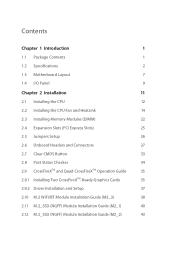
... Contents 1 1.2 Specifications 2 1.3 Motherboard Layout 7 1.4 I/O Panel 9 Chapter 2 Installation 11 2.1 Installing the CPU 12 2.2 Installing the CPU Fan and Heatsink 14 2.3 Installing Memory Modules (DIMM) 22 2.4 Expansion Slots (PCI Express Slots) 25 2.5 Jumpers Setup 26 2.6 Onboard Headers and Connectors 27 2.7 Clear CMOS Button 33 2.8 Post Status Checker 34 2.9 CrossFireXTM and Quad CrossFireXTM Operation Guide 35 2.9.1 Installing Two CrossFireXTM-Ready Graphics Cards 35 2.9.2 Driver Installation and Setup 37 2.10 M.2 WiFi/BT Module Installation Guide (M2_3...
... Contents 1 1.2 Specifications 2 1.3 Motherboard Layout 7 1.4 I/O Panel 9 Chapter 2 Installation 11 2.1 Installing the CPU 12 2.2 Installing the CPU Fan and Heatsink 14 2.3 Installing Memory Modules (DIMM) 22 2.4 Expansion Slots (PCI Express Slots) 25 2.5 Jumpers Setup 26 2.6 Onboard Headers and Connectors 27 2.7 Clear CMOS Button 33 2.8 Post Status Checker 34 2.9 CrossFireXTM and Quad CrossFireXTM Operation Guide 35 2.9.1 Installing Two CrossFireXTM-Ready Graphics Cards 35 2.9.2 Driver Installation and Setup 37 2.10 M.2 WiFi/BT Module Installation Guide (M2_3...
User Manual
Page 7
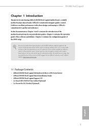
...Steel Legend Quick Installation Guide • ASRock B550M Steel Legend Support CD • 2 x Serial ATA (SATA) Data Cables (Optional) • 2 x Screws for specific information about the model you are using. If you for purchasing ASRock B550M Steel Legend motherboard, a reliable motherboard produced under ASRock's consistently stringent quality control. Chapter 4 contains the configuration guide of the software and utilities. It delivers excellent performance with robust design conforming to ASRock's commitment to quality and endurance. You may find the latest VGA cards and CPU support...
...Steel Legend Quick Installation Guide • ASRock B550M Steel Legend Support CD • 2 x Serial ATA (SATA) Data Cables (Optional) • 2 x Screws for specific information about the model you are using. If you for purchasing ASRock B550M Steel Legend motherboard, a reliable motherboard produced under ASRock's consistently stringent quality control. Chapter 4 contains the configuration guide of the software and utilities. It delivers excellent performance with robust design conforming to ASRock's commitment to quality and endurance. You may find the latest VGA cards and CPU support...

User Manual
Page 8
... x4 mode)* AMD Ryzen series APUs (Renoir) • 2 x PCI Express x16 Slots (PCIE1: Gen3x16 mode; 1.2 Specifications Platform CPU • Micro ATX Form Factor • 2oz Copper PCB • Supports 3rd Gen AMD AM4 Ryzen™ / future AMD Ryzen™ Processors (3000 and 4000 Series Processors)* * Not compatible with AMD Ryzen™ 5 3400G and Ryzen™ 3 3200G. • Digi Power design • 10 Power Phase design Chipset • AMD B550 Memory • Dual Channel DDR4 Memory Technology •...
... x4 mode)* AMD Ryzen series APUs (Renoir) • 2 x PCI Express x16 Slots (PCIE1: Gen3x16 mode; 1.2 Specifications Platform CPU • Micro ATX Form Factor • 2oz Copper PCB • Supports 3rd Gen AMD AM4 Ryzen™ / future AMD Ryzen™ Processors (3000 and 4000 Series Processors)* * Not compatible with AMD Ryzen™ 5 3400G and Ryzen™ 3 3200G. • Digi Power design • 10 Power Phase design Chipset • AMD B550 Memory • Dual Channel DDR4 Memory Technology •...

User Manual
Page 9
... memory default 2GB. B550M Steel Legend Graphics Audio • Supports AMD Quad CrossFireXTM and CrossFireXTM • 15μ Gold Contact in VGA PCIe Slot (PCIE1) • 1 x M.2 Socket (Key E), supports type 2230 WiFi/BT module • Integrated AMD RadeonTM Vega Series Graphics in Ryzen Series APU* * Actual support may vary by independent display controllers • Supports HDMI 2.1 with max. Max Shared memory supports up to 5K (5120x2880)@120Hz • Supports Auto Lip Sync, Deep Color (12bpc), xvYCC and HBR (High Bit Rate Audio) with HDMI 2.1 Port (Compliant HDMI monitor...
... memory default 2GB. B550M Steel Legend Graphics Audio • Supports AMD Quad CrossFireXTM and CrossFireXTM • 15μ Gold Contact in VGA PCIe Slot (PCIE1) • 1 x M.2 Socket (Key E), supports type 2230 WiFi/BT module • Integrated AMD RadeonTM Vega Series Graphics in Ryzen Series APU* * Actual support may vary by independent display controllers • Supports HDMI 2.1 with max. Max Shared memory supports up to 5K (5120x2880)@120Hz • Supports Auto Lip Sync, Deep Color (12bpc), xvYCC and HBR (High Bit Rate Audio) with HDMI 2.1 Port (Compliant HDMI monitor...

User Manual
Page 10
... LAN Port with LED (ACT/LINK LED and SPEED LED) • 1 x Clear CMOS Button • HD Audio Jacks: Rear Speaker / Central / Bass / Line in use, the other one of them is in / Front Speaker / Microphone (Gold Audio Jacks) Storage • 6 x SATA3 6.0 Gb/s Connectors, support RAID (RAID 0, RAID 1 and RAID 10), NCQ, AHCI and Hot Plug* * M2_2 and SATA3_5_6 share lanes. Visual Network Usage Statistics - Smart Auto Adjust Bandwidth Control - If either one will be disabled. • 1 x Hyper M.2 Socket (M2_1), supports M Key type...
... LAN Port with LED (ACT/LINK LED and SPEED LED) • 1 x Clear CMOS Button • HD Audio Jacks: Rear Speaker / Central / Bass / Line in use, the other one of them is in / Front Speaker / Microphone (Gold Audio Jacks) Storage • 6 x SATA3 6.0 Gb/s Connectors, support RAID (RAID 0, RAID 1 and RAID 10), NCQ, AHCI and Hot Plug* * M2_2 and SATA3_5_6 share lanes. Visual Network Usage Statistics - Smart Auto Adjust Bandwidth Control - If either one will be disabled. • 1 x Hyper M.2 Socket (M2_1), supports M Key type...
User Manual
Page 11
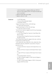
... 1 x 4 pin 12V Power Connector (Hi-Density Power Connec- tor) • 1 x Front Panel Audio Connector • 2 x USB 2.0 Headers (Support 4 USB 2.0 ports) (Supports ESD Protection) • 2 x USB 3.2 Gen1 Headers (Support 4 USB 3.2 Gen1 ports) (Supports ESD Protection) English 5 B550M Steel Legend • 1 x M.2 Socket (M2_2), supports M Key type 2280 M.2 SATA3 6.0 Gb/s module and M.2 PCI Express module up to Gen3 x2 (16 Gb/s)** ** Supports NVMe SSD as boot disks ** Supports ASRock U.2 Kit Connector • 1 x SPI TPM Header • 1 x Power LED and Speaker Header • 2 x RGB LED...
... 1 x 4 pin 12V Power Connector (Hi-Density Power Connec- tor) • 1 x Front Panel Audio Connector • 2 x USB 2.0 Headers (Support 4 USB 2.0 ports) (Supports ESD Protection) • 2 x USB 3.2 Gen1 Headers (Support 4 USB 3.2 Gen1 ports) (Supports ESD Protection) English 5 B550M Steel Legend • 1 x M.2 Socket (M2_2), supports M Key type 2280 M.2 SATA3 6.0 Gb/s module and M.2 PCI Express module up to Gen3 x2 (16 Gb/s)** ** Supports NVMe SSD as boot disks ** Supports ASRock U.2 Kit Connector • 1 x SPI TPM Header • 1 x Power LED and Speaker Header • 2 x RGB LED...

User Manual
Page 14
... Panel Header (PANEL1) 18 Power LED and Speaker Header (SPK_PLED1) 19 USB 3.2 Gen1 Header (F_USB3_3_4) 20 Chassis/Water Pump Fan Connector (CHA_FAN4/WP) 21 Post Status Checker (PSC) 22 SPI TPM Header (SPI_TPM_J1) 23 USB 2.0 Header (USB_3_4) 24 USB 2.0 Header (USB_5_6) 25 Chassis/Water Pump Fan Connector (CHA_FAN2/WP) 26 Chassis/Water Pump Fan Connector (CHA_FAN3/WP) 27 Clear CMOS Jumper (CLRCMOS1) 28 Thunderbolt AIC Connector (TB1) 29 Addressable LED Header (ADDR_LED2) 30 RGB LED Header (RGB_LED2) 31 Front Panel Audio Header (HD_AUDIO1) 32 Chassis...
... Panel Header (PANEL1) 18 Power LED and Speaker Header (SPK_PLED1) 19 USB 3.2 Gen1 Header (F_USB3_3_4) 20 Chassis/Water Pump Fan Connector (CHA_FAN4/WP) 21 Post Status Checker (PSC) 22 SPI TPM Header (SPI_TPM_J1) 23 USB 2.0 Header (USB_3_4) 24 USB 2.0 Header (USB_5_6) 25 Chassis/Water Pump Fan Connector (CHA_FAN2/WP) 26 Chassis/Water Pump Fan Connector (CHA_FAN3/WP) 27 Clear CMOS Jumper (CLRCMOS1) 28 Thunderbolt AIC Connector (TB1) 29 Addressable LED Header (ADDR_LED2) 30 RGB LED Header (RGB_LED2) 31 Front Panel Audio Header (HD_AUDIO1) 32 Chassis...
User Manual
Page 17
... you install the motherboard, study the configuration of the following precautions before you install motherboard components or change any components, place them on a carpet. Failure to do so may damage the motherboard. 11 English Also remember to use a grounded wrist strap or touch a safety grounded object before installing or removing the motherboard. Doing so may cause physical injuries to you uninstall any motherboard settings...
... you install the motherboard, study the configuration of the following precautions before you install motherboard components or change any components, place them on a carpet. Failure to do so may damage the motherboard. 11 English Also remember to use a grounded wrist strap or touch a safety grounded object before installing or removing the motherboard. Doing so may cause physical injuries to you uninstall any motherboard settings...
User Manual
Page 31
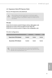
... the card before you start the installation. PCIe slots: PCIE1 (PCIe 4.0 x16 slot) is used for PCI Express x16 lane width graphics cards. B550M Steel Legend 2.4 Expansion Slots (PCI Express Slots) There are 3 PCI Express slots on the motherboard. Before installing an expansion card, please make necessary hardware settings for PCI Express x4 lane width graphics cards. PCIe Slot Configurations Ryzen Series CPUs (Matisse) PCIE1 Gen4x16 PCIE2 Gen3x1 PCIE3 Gen3x4 Ryzen Series CPUs (Renoir) Gen3x16 Gen3x1 Gen3x4 For a better thermal environment, please connect a chassis fan to...
... the card before you start the installation. PCIe slots: PCIE1 (PCIe 4.0 x16 slot) is used for PCI Express x16 lane width graphics cards. B550M Steel Legend 2.4 Expansion Slots (PCI Express Slots) There are 3 PCI Express slots on the motherboard. Before installing an expansion card, please make necessary hardware settings for PCI Express x4 lane width graphics cards. PCIe Slot Configurations Ryzen Series CPUs (Matisse) PCIE1 Gen4x16 PCIE2 Gen3x1 PCIE3 Gen3x4 Ryzen Series CPUs (Renoir) Gen3x16 Gen3x1 Gen3x4 For a better thermal environment, please connect a chassis fan to...
User Manual
Page 33
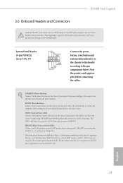
.... The LED is on the chassis front panel. PWRBTN (Power Button): Connect to the power status indicator on the chassis front panel. When connecting your chassis front panel module to turn off (S5). English 27 The front panel design may configure the way to this header according to the reset button on the chassis front panel. You may differ by chassis. B550M Steel Legend 2.6 Onboard Headers and Connectors Onboard headers and connectors are matched correctly. Placing jumper caps over these headers and connectors.
.... The LED is on the chassis front panel. PWRBTN (Power Button): Connect to the power status indicator on the chassis front panel. When connecting your chassis front panel module to turn off (S5). English 27 The front panel design may configure the way to this header according to the reset button on the chassis front panel. You may differ by chassis. B550M Steel Legend 2.6 Onboard Headers and Connectors Onboard headers and connectors are matched correctly. Placing jumper caps over these headers and connectors.
User Manual
Page 35
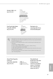
... HD audio panel only. If you plan to connect a 3-Pin chassis water cooler fan, please connect it to Pin 1-3. 29 E. You don't need to function correctly. B550M Steel Legend (19-pin F_USB3_3_4) (see p.7, No. 19) IntA_P_D+ IntA_P_DGND IntA_P_SSTX+ IntA_P_SSTXGND IntA_P_SSRX+ IntA_P_SSRXVbus 1 Vbus IntA_P_SSRXIntA_P_SSRX+ GND IntA_P_SSTXIntA_P_SSTX+ GND IntA_P_DIntA_P_D+ ID Front Panel Audio Header (9-pin HD_AUDIO1) (see p.7, No. 31) 3 4 GND FAN_VOLTAGE CHA_FAN_SPEED FAN_SPEED_CONTROL This motherboard provides four 4-Pin water cooling chassis fan connectors...
... HD audio panel only. If you plan to connect a 3-Pin chassis water cooler fan, please connect it to Pin 1-3. 29 E. You don't need to function correctly. B550M Steel Legend (19-pin F_USB3_3_4) (see p.7, No. 19) IntA_P_D+ IntA_P_DGND IntA_P_SSTX+ IntA_P_SSTXGND IntA_P_SSRX+ IntA_P_SSRXVbus 1 Vbus IntA_P_SSRXIntA_P_SSRX+ GND IntA_P_SSTXIntA_P_SSTX+ GND IntA_P_DIntA_P_D+ ID Front Panel Audio Header (9-pin HD_AUDIO1) (see p.7, No. 31) 3 4 GND FAN_VOLTAGE CHA_FAN_SPEED FAN_SPEED_CONTROL This motherboard provides four 4-Pin water cooling chassis fan connectors...
User Manual
Page 37
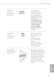
... network security, protects digital identities, and ensures platform integrity. To use a 4-pin ATX power supply, please plug it along Pin 1 and Pin 5. *Warning: Please make sure that the power cable connected is optional. *The power supply plug fits into this connector. SPI TPM Header (13-pin SPI_TPM_J1) (see p.7, No. 1) This motherboard provides an 8-pin ATX 12V power connector. English 31 ATX 12V Power Connector (4-pin ATX12V2) (see p.7, No. 2) Please connect an ATX 12V power supply to this connector in only one orientation. B550M Steel Legend ATX 12V Power...
... network security, protects digital identities, and ensures platform integrity. To use a 4-pin ATX power supply, please plug it along Pin 1 and Pin 5. *Warning: Please make sure that the power cable connected is optional. *The power supply plug fits into this connector. SPI TPM Header (13-pin SPI_TPM_J1) (see p.7, No. 1) This motherboard provides an 8-pin ATX 12V power connector. English 31 ATX 12V Power Connector (4-pin ATX12V2) (see p.7, No. 2) Please connect an ATX 12V power supply to this connector in only one orientation. B550M Steel Legend ATX 12V Power...
User Manual
Page 41
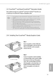
B550M Steel Legend 2.9 CrossFireXTM and Quad CrossFireXTM Operation Guide This motherboard supports CrossFireXTM and Quad CrossFireXTM that are properly seated on the top of the graphics cards. (The CrossFire Bridge is recommended to enable CrossFireXTM. Please refer to PCIE3 slot. Download the drivers from the AMD's website: www.amd.com 3. Please refer to the AMD's website for detailed installation guide. 2.9.1 Installing Two CrossFireXTM-Ready Graphics Cards Step 1 Insert one graphics card into PCIE1...
B550M Steel Legend 2.9 CrossFireXTM and Quad CrossFireXTM Operation Guide This motherboard supports CrossFireXTM and Quad CrossFireXTM that are properly seated on the top of the graphics cards. (The CrossFire Bridge is recommended to enable CrossFireXTM. Please refer to PCIE3 slot. Download the drivers from the AMD's website: www.amd.com 3. Please refer to the AMD's website for detailed installation guide. 2.9.1 Installing Two CrossFireXTM-Ready Graphics Cards Step 1 Insert one graphics card into PCIE1...
User Manual
Page 43
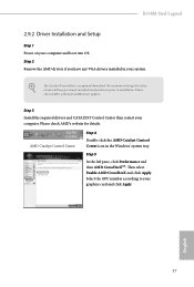
... and boot into OS. AMD Catalyst Control Center Step 4 Double-click the AMD Catalyst Control Center icon in your graphics card and click Apply. We recommend using this utility to uninstall any VGA drivers installed in the Windows® system tray. B550M Steel Legend 2.9.2 Driver Installation and Setup Step 1 Power on your computer. Step 5 In the left pane, click Performance and then AMD CrossFireXTM. Please check AMD's website for AMD driver updates. Step 2 Remove the AMD drivers if...
... and boot into OS. AMD Catalyst Control Center Step 4 Double-click the AMD Catalyst Control Center icon in your graphics card and click Apply. We recommend using this utility to uninstall any VGA drivers installed in the Windows® system tray. B550M Steel Legend 2.9.2 Driver Installation and Setup Step 1 Power on your computer. Step 5 In the left pane, click Performance and then AMD CrossFireXTM. Please check AMD's website for AMD driver updates. Step 2 Remove the AMD drivers if...
User Manual
Page 52
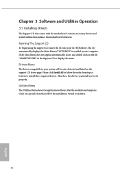
... to display the menu. The CD automatically displays the Main Menu if "AUTORUN" is enabled in the Support CD to install it. 46 English Drivers Menu The drivers compatible to install those required drivers. Running The Support CD To begin using the support CD, insert the CD into your system will be auto-detected and listed on a specific item then follow the order from top to bottom to your CD-ROM drive.
... to display the menu. The CD automatically displays the Main Menu if "AUTORUN" is enabled in the Support CD to install it. 46 English Drivers Menu The drivers compatible to install those required drivers. Running The Support CD To begin using the support CD, insert the CD into your system will be auto-detected and listed on a specific item then follow the order from top to bottom to your CD-ROM drive.
User Manual
Page 69
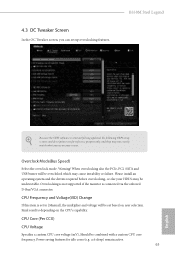
... being updated, the following UEFI setup screens and descriptions are for idle cores (e.g. Power saving features for reference purpose only, and they may not exactly match what you can set based on user selection. Final result is connected via the onboard D-Bus/VGA connector. cc6 sleep) remain active. 63 English Overclocking is not supported if the monitor is depending on the CPU's capability. Warning! When overclocking also the PCIe, PCI, SATA and USB...
... being updated, the following UEFI setup screens and descriptions are for idle cores (e.g. Power saving features for reference purpose only, and they may not exactly match what you can set based on user selection. Final result is connected via the onboard D-Bus/VGA connector. cc6 sleep) remain active. 63 English Overclocking is not supported if the monitor is depending on the CPU's capability. Warning! When overclocking also the PCIe, PCI, SATA and USB...


