
RAID Installation Guide
Page 2
... a SATA driver diskette, press or to enter BIOS setup to set . Hot-Plug any fault tolerance. WARNING!! It provides data protection and increases fault tolerance to the entire system since it does not provide any HDDs of the same model and capacity when creating a RAID set the option to RAID mode by using the onboard FastBuild BIOS utility under BIOS environment. For optimal performance, please install identical drives of the RAID 0 Disk will...
... a SATA driver diskette, press or to enter BIOS setup to set . Hot-Plug any fault tolerance. WARNING!! It provides data protection and increases fault tolerance to the entire system since it does not provide any HDDs of the same model and capacity when creating a RAID set the option to RAID mode by using the onboard FastBuild BIOS utility under BIOS environment. For optimal performance, please install identical drives of the RAID 0 Disk will...

RAID Installation Guide
Page 8
... install the DVD-ROM. E. STEP 3.2: Download driver from ASRock's website and unzip the file into your USB flash drive. 8 Click to finish the driver copy process. Go to finish the configuration. STEP 4: Windows installation A. A. C. STEP 3.1: Copy RAID driver to a USB flash drive You can choose either STEP 3.1 or STEP 3.2 to Tools Easy RAID Installer F. B. During system boot, press or key to enter UEFI setup utility. Insert the Support CD into one of the USB port. Please download the "SATA Floppy Imaged driver" from ASRock...
... install the DVD-ROM. E. STEP 3.2: Download driver from ASRock's website and unzip the file into your USB flash drive. 8 Click to finish the driver copy process. Go to finish the configuration. STEP 4: Windows installation A. A. C. STEP 3.1: Copy RAID driver to a USB flash drive You can choose either STEP 3.1 or STEP 3.2 to Tools Easy RAID Installer F. B. During system boot, press or key to enter UEFI setup utility. Insert the Support CD into one of the USB port. Please download the "SATA Floppy Imaged driver" from ASRock...

RAID Installation Guide
Page 12
... USB flash disk. 12 STEP 2.1: Copy RAID driver to a USB flash drive You can choose either STEP2.1 or STEP2.2 to Tools Easy RAID Installer F. D. Go to finish the configuration. Click to save to enter UEFI setup utility. B. During system boot, press or key to exit. Insert the Support CD into one of the USB port. C. Follow instructions to delete the existing disk arrays before creating a new array. H. Please install the DVD-ROM. Please download the "SATA Floppy...
... USB flash disk. 12 STEP 2.1: Copy RAID driver to a USB flash drive You can choose either STEP2.1 or STEP2.2 to Tools Easy RAID Installer F. D. Go to finish the configuration. Click to save to enter UEFI setup utility. B. During system boot, press or key to exit. Insert the Support CD into one of the USB port. C. Follow instructions to delete the existing disk arrays before creating a new array. H. Please install the DVD-ROM. Please download the "SATA Floppy...

Quick Installation Guide
Page 4
... DDR4_B1) 5 2 x 288-pin DDR4 DIMM Slots (DDR4_A2, DDR4_B2) 6 AMD Fan LED Header (AMD_FAN_LED1) 7 ATX Power Connector (ATXPWR1) 8 USB 3.1 Gen1 Header (USB3_56) 9 SATA3 Connector (SATA3_3) 10 SATA3 Connector (SATA3_4) 11 SATA3 Connector (SATA3_2) 12 SATA3 Connector (SATA3_1) 13 System Panel Header (PANEL1) 14 Power LED and Speaker Header (SPK_PLED1) 15 Chassis Intrusion Header (CI1) 16 Chassis/Water Pump Fan Connector (CHA_FAN2/WP) 17 Chassis/Water Pump Fan Connector (CHA_FAN3/WP) 18 Clear CMOS Jumper (CLRCMOS1) 19 USB 2.0 Header (USB_5_6) 20 USB 2.0 Header (USB_3_4) 21 COM Port Header (COM1) 22...
... DDR4_B1) 5 2 x 288-pin DDR4 DIMM Slots (DDR4_A2, DDR4_B2) 6 AMD Fan LED Header (AMD_FAN_LED1) 7 ATX Power Connector (ATXPWR1) 8 USB 3.1 Gen1 Header (USB3_56) 9 SATA3 Connector (SATA3_3) 10 SATA3 Connector (SATA3_4) 11 SATA3 Connector (SATA3_2) 12 SATA3 Connector (SATA3_1) 13 System Panel Header (PANEL1) 14 Power LED and Speaker Header (SPK_PLED1) 15 Chassis Intrusion Header (CI1) 16 Chassis/Water Pump Fan Connector (CHA_FAN2/WP) 17 Chassis/Water Pump Fan Connector (CHA_FAN3/WP) 18 Clear CMOS Jumper (CLRCMOS1) 19 USB 2.0 Header (USB_5_6) 20 USB 2.0 Header (USB_3_4) 21 COM Port Header (COM1) 22...
Quick Installation Guide
Page 7
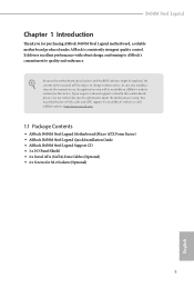
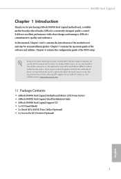
... Guide • ASRock B450M Steel Legend Support CD • 1 x I/O Panel Shield • 2 x Serial ATA (SATA) Data Cables (Optional) • 2 x Screws for purchasing ASRock B450M Steel Legend motherboard, a reliable motherboard produced under ASRock's consistently stringent quality control. If you require technical support related to this motherboard, please visit our website for specific information about the model you for M.2 Sockets (Optional) 5 English B450M Steel Legend Chapter 1 Introduction Thank you are using. In case any modifications of this manual occur, the updated...
... Guide • ASRock B450M Steel Legend Support CD • 1 x I/O Panel Shield • 2 x Serial ATA (SATA) Data Cables (Optional) • 2 x Screws for purchasing ASRock B450M Steel Legend motherboard, a reliable motherboard produced under ASRock's consistently stringent quality control. If you require technical support related to this motherboard, please visit our website for specific information about the model you for M.2 Sockets (Optional) 5 English B450M Steel Legend Chapter 1 Introduction Thank you are using. In case any modifications of this manual occur, the updated...

Quick Installation Guide
Page 11
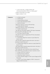
... CHA_FAN3/WP can auto detect if 3-pin or 4-pin fan is in use. • 1 x 24 pin ATX Power Connector • 1 x 8 pin 12V Power Connector • 1 x Front Panel Audio Connector • 2 x USB 2.0 Headers (Support 4 USB 2.0 ports) (Supports ESD Protection) • 1 x USB 3.1 Gen1 Header (Supports 2 USB 3.1 Gen1 ports) (Supports ESD Protection) BIOS Feature • AMI UEFI Legal BIOS with multilingual GUI support • Supports "Plug and Play" • ACPI 5.1 compliance wake up events • Supports jumperfree • SMBIOS 2.3 support • DRAM Voltage multi-adjustment English...
... CHA_FAN3/WP can auto detect if 3-pin or 4-pin fan is in use. • 1 x 24 pin ATX Power Connector • 1 x 8 pin 12V Power Connector • 1 x Front Panel Audio Connector • 2 x USB 2.0 Headers (Support 4 USB 2.0 ports) (Supports ESD Protection) • 1 x USB 3.1 Gen1 Header (Supports 2 USB 3.1 Gen1 ports) (Supports ESD Protection) BIOS Feature • AMI UEFI Legal BIOS with multilingual GUI support • Supports "Plug and Play" • ACPI 5.1 compliance wake up events • Supports jumperfree • SMBIOS 2.3 support • DRAM Voltage multi-adjustment English...

Quick Installation Guide
Page 13
...; Whenever you uninstall any motherboard settings. • Make sure to the chassis, please do so may damage the motherboard. 11 English Pre-installation Precautions Take note of your motherboard directly on a grounded anti-static pad or in the bag that the motherboard fits into it. Failure to do not overtighten the screws! B450M Steel Legend Chapter 2 Installation This is a Micro ATX form factor...
...; Whenever you uninstall any motherboard settings. • Make sure to the chassis, please do so may damage the motherboard. 11 English Pre-installation Precautions Take note of your motherboard directly on a grounded anti-static pad or in the bag that the motherboard fits into it. Failure to do not overtighten the screws! B450M Steel Legend Chapter 2 Installation This is a Micro ATX form factor...

Quick Installation Guide
Page 27
... hardware settings for PCI Express x16 lane width graphics cards. PCIe slots: PCIE1 (PCIe 2.0 x1 slot) is unplugged. English 25 Please read the documentation of the expansion card and make sure that the power supply is switched off or the power cord is used for the card before you start the installation. PCIE2 (PCIe 3.0 x16 slot) is used for PCI Express x1 lane width cards. B450M Steel Legend 2.4 Expansion Slots (PCI Express Slots) There are 3 PCI Express slots on the motherboard. PCIE3 (PCIe 2.0 x16 slot) is used for PCI Express...
... hardware settings for PCI Express x16 lane width graphics cards. PCIe slots: PCIE1 (PCIe 2.0 x1 slot) is unplugged. English 25 Please read the documentation of the expansion card and make sure that the power supply is switched off or the power cord is used for the card before you start the installation. PCIE2 (PCIe 3.0 x16 slot) is used for PCI Express x1 lane width cards. B450M Steel Legend 2.4 Expansion Slots (PCI Express Slots) There are 3 PCI Express slots on the motherboard. PCIE3 (PCIe 2.0 x16 slot) is used for PCI Express...

Quick Installation Guide
Page 30
These four SATA3 connectors support SATA data cables for connecting audio devices to 6.0 Gb/s data transfer rate. * M2_2 and SATA3_3 share lanes. Each USB 2.0 header can support two ports. Power LED and Speaker Header (7-pin SPK_PLED1) (see p.1, No. 14) Serial ATA3 Connectors (SATA3_1: see p.1, No. 12) (SATA3_2: see p.1, No. 11) (SATA3_3: see p.1, No. 9) (SATA3_4: see p.1, No. 10) USB 2.0 Headers (9-pin USB_3_4) (see p.1, No. 20) (9-pin USB_5_6) (see p.1 or 8, No. 8) Vbus IntA_PA_SSRXIntA_PA_SSRX+ GND IntA_PA_SSTXIntA_PA_SSTX...
These four SATA3 connectors support SATA data cables for connecting audio devices to 6.0 Gb/s data transfer rate. * M2_2 and SATA3_3 share lanes. Each USB 2.0 header can support two ports. Power LED and Speaker Header (7-pin SPK_PLED1) (see p.1, No. 14) Serial ATA3 Connectors (SATA3_1: see p.1, No. 12) (SATA3_2: see p.1, No. 11) (SATA3_3: see p.1, No. 9) (SATA3_4: see p.1, No. 10) USB 2.0 Headers (9-pin USB_3_4) (see p.1, No. 20) (9-pin USB_5_6) (see p.1 or 8, No. 8) Vbus IntA_PA_SSRXIntA_PA_SSRX+ GND IntA_PA_SSTXIntA_PA_SSTX...

User Manual
Page 4
...Contents 1 1.2 Specifications 2 1.3 Motherboard Layout 7 1.4 I/O Panel 9 Chapter 2 Installation 11 2.1 Installing the CPU 12 2.2 Installing the CPU Fan and Heatsink 14 2.3 Installing Memory Modules (DIMM) 22 2.4 Expansion Slots (PCI Express Slots) 26 2.5 Jumpers Setup 27 2.6 Onboard Headers and Connectors 28 2.7 CrossFireXTM and Quad CrossFireXTM Operation Guide 33 2.7.1 Installing Two CrossFireXTM-Ready Graphics Cards 33 2.7.2 Driver Installation and Setup 35 2.8 M.2_SSD (NGFF) Module Installation Guide (M2_1) 36 2.9 M.2_SSD (NGFF) Module Installation Guide (M2_2...
...Contents 1 1.2 Specifications 2 1.3 Motherboard Layout 7 1.4 I/O Panel 9 Chapter 2 Installation 11 2.1 Installing the CPU 12 2.2 Installing the CPU Fan and Heatsink 14 2.3 Installing Memory Modules (DIMM) 22 2.4 Expansion Slots (PCI Express Slots) 26 2.5 Jumpers Setup 27 2.6 Onboard Headers and Connectors 28 2.7 CrossFireXTM and Quad CrossFireXTM Operation Guide 33 2.7.1 Installing Two CrossFireXTM-Ready Graphics Cards 33 2.7.2 Driver Installation and Setup 35 2.8 M.2_SSD (NGFF) Module Installation Guide (M2_1) 36 2.9 M.2_SSD (NGFF) Module Installation Guide (M2_2...
User Manual
Page 7
... guide of the BIOS setup. In this motherboard, please visit our website for specific information about the model you are using. In case any modifications of this manual will be subject to change without further notice. ASRock website http://www.asrock.com. 1.1 Package Contents • ASRock B450M Steel Legend Motherboard (Micro ATX Form Factor) • ASRock B450M Steel Legend Quick Installation Guide • ASRock B450M Steel Legend Support CD • 1 x I/O Panel Shield • 2 x Serial ATA (SATA) Data Cables (Optional) • 2 x Screws for purchasing ASRock B450M Steel Legend...
... guide of the BIOS setup. In this motherboard, please visit our website for specific information about the model you are using. In case any modifications of this manual will be subject to change without further notice. ASRock website http://www.asrock.com. 1.1 Package Contents • ASRock B450M Steel Legend Motherboard (Micro ATX Form Factor) • ASRock B450M Steel Legend Quick Installation Guide • ASRock B450M Steel Legend Support CD • 1 x I/O Panel Shield • 2 x Serial ATA (SATA) Data Cables (Optional) • 2 x Screws for purchasing ASRock B450M Steel Legend...
User Manual
Page 11
B450M Steel Legend • 1 x M.2 Socket (M2_2), supports M Key type 2230/2242/2260/2280 M.2 SATA3 6.0 Gb/s module** ** Supports NVMe SSD as boot disks ** Supports ASRock U.2 Kit Connector • 1 x COM Port Header • 1 x TPM Header • 1 x Chassis Intrusion Header • 1 x Power LED and Speaker Header • 1 x RGB LED Header * Supports in total up to 12V/3A, 36W LED Strip • 1 x Addressable LED Header * Supports in total up to 5V/3A, 15W LED Strip • 1 x AMD Fan LED Header * The AMD Fan LED Header supports LED strips of maximum load of 3A (36W) and length...
B450M Steel Legend • 1 x M.2 Socket (M2_2), supports M Key type 2230/2242/2260/2280 M.2 SATA3 6.0 Gb/s module** ** Supports NVMe SSD as boot disks ** Supports ASRock U.2 Kit Connector • 1 x COM Port Header • 1 x TPM Header • 1 x Chassis Intrusion Header • 1 x Power LED and Speaker Header • 1 x RGB LED Header * Supports in total up to 12V/3A, 36W LED Strip • 1 x Addressable LED Header * Supports in total up to 5V/3A, 15W LED Strip • 1 x AMD Fan LED Header * The AMD Fan LED Header supports LED strips of maximum load of 3A (36W) and length...

User Manual
Page 35
...+ GND IntA_PA_SSTXIntA_PA_SSTX+ GND IntA_PA_DIntA_PA_D+ Vbus IntA_PB_SSRXIntA_PB_SSRX+ GND IntA_PB_SSTXIntA_PB_SSTX+ GND IntA_PB_DIntA_PB_D+ Dummy 1 There is one will be disabled. Each USB 2.0 header can support two ports. These four SATA3 connectors support SATA data cables for connecting audio devices to the front audio panel. 29 English B450M Steel Legend Power LED and Speaker Header (7-pin SPK_PLED1) (see p.7, No. 14) Serial ATA3 Connectors (SATA3_1: see p.7, No. 12) (SATA3_2: see p.7, No. 11) (SATA3_3: see p.7, No. 9) (SATA3_4: see p.7, No. 10...
...+ GND IntA_PA_SSTXIntA_PA_SSTX+ GND IntA_PA_DIntA_PA_D+ Vbus IntA_PB_SSRXIntA_PB_SSRX+ GND IntA_PB_SSTXIntA_PB_SSTX+ GND IntA_PB_DIntA_PB_D+ Dummy 1 There is one will be disabled. Each USB 2.0 header can support two ports. These four SATA3 connectors support SATA data cables for connecting audio devices to the front audio panel. 29 English B450M Steel Legend Power LED and Speaker Header (7-pin SPK_PLED1) (see p.7, No. 14) Serial ATA3 Connectors (SATA3_1: see p.7, No. 12) (SATA3_2: see p.7, No. 11) (SATA3_3: see p.7, No. 9) (SATA3_4: see p.7, No. 10...

User Manual
Page 39
... in CrossFireXTM mode. 5. Make sure that your power supply unit (PSU) can provide at least the minimum power your system requires. If you to install up to enable CrossFireXTM. CrossFire Bridge Step 2 Connect two graphics cards by installing a CrossFire Bridge on the CrossFire Bridge Interconnects on the slots. You should only use a AMD certified PSU. B450M Steel Legend 2.7 CrossFireXTM and Quad CrossFireXTM Operation Guide This motherboard supports CrossFireXTM and...
... in CrossFireXTM mode. 5. Make sure that your power supply unit (PSU) can provide at least the minimum power your system requires. If you to install up to enable CrossFireXTM. CrossFire Bridge Step 2 Connect two graphics cards by installing a CrossFire Bridge on the CrossFire Bridge Interconnects on the slots. You should only use a AMD certified PSU. B450M Steel Legend 2.7 CrossFireXTM and Quad CrossFireXTM Operation Guide This motherboard supports CrossFireXTM and...
User Manual
Page 41
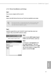
.... Step 2 Remove the AMD drivers if you have any previously installed Catalyst drivers prior to your system. The Catalyst Uninstaller is an optional download. Step 3 Install the required drivers and CATALYST Control Center then restart your computer and boot into OS. We recommend using this utility to uninstall any VGA drivers installed in the Windows® system tray. English 35 Please check AMD's website for AMD driver updates. B450M Steel Legend 2.7.2 Driver Installation and Setup Step 1 Power on...
.... Step 2 Remove the AMD drivers if you have any previously installed Catalyst drivers prior to your system. The Catalyst Uninstaller is an optional download. Step 3 Install the required drivers and CATALYST Control Center then restart your computer and boot into OS. We recommend using this utility to uninstall any VGA drivers installed in the Windows® system tray. English 35 Please check AMD's website for AMD driver updates. B450M Steel Legend 2.7.2 Driver Installation and Setup Step 1 Power on...
User Manual
Page 48
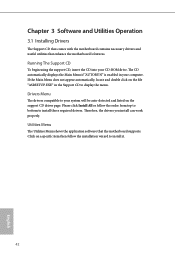
The CD automatically displays the Main Menu if "AUTORUN" is enabled in the Support CD to display the menu. Drivers Menu The drivers compatible to your system will be auto-detected and listed on the file "ASRSETUP.EXE" in your CD-ROM drive. Therefore, the drivers you install can work properly. If the Main Menu does not appear automatically, locate and double click on the support CD driver page. Utilities Menu The Utilities Menu shows the application software that enhance...
The CD automatically displays the Main Menu if "AUTORUN" is enabled in the Support CD to display the menu. Drivers Menu The drivers compatible to your system will be auto-detected and listed on the file "ASRSETUP.EXE" in your CD-ROM drive. Therefore, the drivers you install can work properly. If the Main Menu does not appear automatically, locate and double click on the support CD driver page. Utilities Menu The Utilities Menu shows the application software that enhance...

User Manual
Page 72
PS2 Y-Cable Enable the PS2 Y-Cable or set this option to Auto. 66 English 4.4.5 Super IO Configuration Serial Port Enable or disable the Serial port. Serial Port Address Select the address of the Serial port.
PS2 Y-Cable Enable the PS2 Y-Cable or set this option to Auto. 66 English 4.4.5 Super IO Configuration Serial Port Enable or disable the Serial port. Serial Port Address Select the address of the Serial port.

User Manual
Page 76
... error Controls DF::PIEConfig[DisImmSyncFloodOnFatalError] Disabling this field are from 0x1 (1) - 0x10 (16). Once this option has been used . Core/Thread Enablement Downcore control Sets the number of hours to take effect. Opcache Control Enables or disables the Opcache. SMTEN This item can be used to be used to remove any cores, a POWER CYCLE is needed after selecting the 'Auto' option. The valid values for future selections to scrub memory...
... error Controls DF::PIEConfig[DisImmSyncFloodOnFatalError] Disabling this field are from 0x1 (1) - 0x10 (16). Once this option has been used . Core/Thread Enablement Downcore control Sets the number of hours to take effect. Opcache Control Enables or disables the Opcache. SMTEN This item can be used to be used to remove any cores, a POWER CYCLE is needed after selecting the 'Auto' option. The valid values for future selections to scrub memory...
User Manual
Page 84
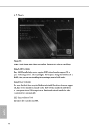
... drivers please change the SATA mode to RAID, then you to adjust the RGB LED color to your system via an USB storage device, then downloads and installs the other required drivers automatically. Easy Driver Installer For users that installs the LAN driver to securely erase SSD. 78 English 4.5 Tools RGB LED ASRock Polychrome RGB allows you can start installing the operating system in the UEFI that don't have an optical disk drive to install the drivers...
... drivers please change the SATA mode to RAID, then you to adjust the RGB LED color to your system via an USB storage device, then downloads and installs the other required drivers automatically. Easy Driver Installer For users that installs the LAN driver to securely erase SSD. 78 English 4.5 Tools RGB LED ASRock Polychrome RGB allows you can start installing the operating system in the UEFI that don't have an optical disk drive to install the drivers...
User Manual
Page 85
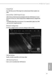
...(Auto IP), Auto ASRock Internet Flash downloads and updates the latest UEFI firmware version from our servers for Internet Flash. Please setup network configuration before using Internet Flash. *For BIOS backup and recovery purpose, it is recommended to plug in your USB pen drive before using this to configure internet connection settings for you. Internet Setting Enable or disable sound effects in the setup utility. Network Configuration Use this function. B450M Steel Legend Instant Flash Save UEFI files in your USB storage device and run Instant Flash to download the UEFI firmware...
...(Auto IP), Auto ASRock Internet Flash downloads and updates the latest UEFI firmware version from our servers for Internet Flash. Please setup network configuration before using Internet Flash. *For BIOS backup and recovery purpose, it is recommended to plug in your USB pen drive before using this to configure internet connection settings for you. Internet Setting Enable or disable sound effects in the setup utility. Network Configuration Use this function. B450M Steel Legend Instant Flash Save UEFI files in your USB storage device and run Instant Flash to download the UEFI firmware...


