
Quick Installation Guide
Page 4
... (SATA3_1) 13 System Panel Header (PANEL1) 14 Power LED and Speaker Header (SPK_PLED1) 15 Chassis Intrusion Header (CI1) 16 Chassis Fan Connector (CHA_FAN2) 17 USB 2.0 Header (USB_3_4) 18 USB 2.0 Header (USB_5_6) 19 Clear CMOS Jumper (CLRCMOS1) 20 RGB LED Header (RGB_HEADER1) 21 Addressable LED Header (ADDR_LED1) 22 Front Panel Audio Header (HD_AUDIO1) 23 Chassis/Water Pump Fan Connector (CHA_FAN1) 2 English...
... (SATA3_1) 13 System Panel Header (PANEL1) 14 Power LED and Speaker Header (SPK_PLED1) 15 Chassis Intrusion Header (CI1) 16 Chassis Fan Connector (CHA_FAN2) 17 USB 2.0 Header (USB_3_4) 18 USB 2.0 Header (USB_5_6) 19 Clear CMOS Jumper (CLRCMOS1) 20 RGB LED Header (RGB_HEADER1) 21 Addressable LED Header (ADDR_LED1) 22 Front Panel Audio Header (HD_AUDIO1) 23 Chassis/Water Pump Fan Connector (CHA_FAN1) 2 English...
Quick Installation Guide
Page 9
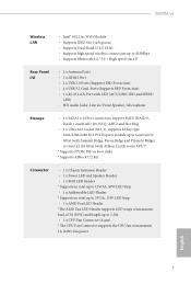
English 7 B450M/ac Wireless LAN • Intel® 802.11ac WiFi Module • Supports IEEE 802.11a/b/g/n/ac • Supports Dual-Band (2.4/5 GHz) • Supports high speed wireless connections up to 433Mbps • Supports Bluetooth 4.2 / 3.0 + High speed class II... ASRock U.2 Kit Connector • 1 x Chassis Intrusion Header • 1 x Power LED and Speaker Header • 1 x RGB LED Header * Supports in total up to 12V/3A, 36W LED Strip • 1 x Addressable LED Header * Supports in total up to 5V/3A, 15W LED Strip • 1 x AMD Fan LED Header *The AMD Fan LED Header ...
English 7 B450M/ac Wireless LAN • Intel® 802.11ac WiFi Module • Supports IEEE 802.11a/b/g/n/ac • Supports Dual-Band (2.4/5 GHz) • Supports high speed wireless connections up to 433Mbps • Supports Bluetooth 4.2 / 3.0 + High speed class II... ASRock U.2 Kit Connector • 1 x Chassis Intrusion Header • 1 x Power LED and Speaker Header • 1 x RGB LED Header * Supports in total up to 12V/3A, 36W LED Strip • 1 x Addressable LED Header * Supports in total up to 5V/3A, 15W LED Strip • 1 x AMD Fan LED Header *The AMD Fan LED Header ...

Quick Installation Guide
Page 10
.... • 1 x 24 pin ATX Power Connector • 1 x 8 pin 12V Power Connector • 1 x Front Panel Audio Connector • 1 x AMD LED Fan USB Header • 2 x USB 2.0 Headers (Support 4 USB 2.0 ports) (Supports ESD Protection) • 1 x USB 3.2 Gen1 Header (Supports 2 USB 3.2 Gen1 ports) (Supports ESD Protection) • AMI UEFI Legal BIOS with multilingual GUI support • Supports "Plug...
.... • 1 x 24 pin ATX Power Connector • 1 x 8 pin 12V Power Connector • 1 x Front Panel Audio Connector • 1 x AMD LED Fan USB Header • 2 x USB 2.0 Headers (Support 4 USB 2.0 ports) (Supports ESD Protection) • 1 x USB 3.2 Gen1 Header (Supports 2 USB 3.2 Gen1 ports) (Supports ESD Protection) • AMI UEFI Legal BIOS with multilingual GUI support • Supports "Plug...

Quick Installation Guide
Page 19
B450M/ac 4 CPU_FAN1 5 RGB LED Cable 4-pin FAN cable CPU_FAN1 +12V AMD_FAN_LED1 *The diagram shown here are for the orientation of AMD Fan LED Header (AMD_FAN_LED1). 17 English Please refer to page 32 for reference only.
B450M/ac 4 CPU_FAN1 5 RGB LED Cable 4-pin FAN cable CPU_FAN1 +12V AMD_FAN_LED1 *The diagram shown here are for the orientation of AMD Fan LED Header (AMD_FAN_LED1). 17 English Please refer to page 32 for reference only.

Quick Installation Guide
Page 23
Please refer to page 32 for the orientation of AMD Fan LED Header (AMD_FAN_LED1) and page 29 for reference only. B450M/ac 6 CPU_FAN1 +12V AMD_FAN_LED1 or 7 CPU_FAN1 AMD_FAN_LED1 USB_5 Please note that only one cable should be used at a time in this step. If you select USB connector, please install AMD utility "SR3 Settings Software". *The diagram shown here are for the orientation of AMD LED Fan USB Header (USB_7). 21 English If you select AMD_FAN_LED1, please install ASRock utility "ASRock Polychrome SYNC".
Please refer to page 32 for the orientation of AMD Fan LED Header (AMD_FAN_LED1) and page 29 for reference only. B450M/ac 6 CPU_FAN1 +12V AMD_FAN_LED1 or 7 CPU_FAN1 AMD_FAN_LED1 USB_5 Please note that only one cable should be used at a time in this step. If you select USB connector, please install AMD utility "SR3 Settings Software". *The diagram shown here are for the orientation of AMD LED Fan USB Header (USB_7). 21 English If you select AMD_FAN_LED1, please install ASRock utility "ASRock Polychrome SYNC".

Quick Installation Guide
Page 30
... p.1, No. 14) Serial ATA3 Connectors (SATA3_1: see p.1, No. 12) (SATA3_2: see p.1, No. 11) (SATA3_3: see p.1, No. 9) (SATA3_4: see p.1, No. 10) AMD LED Fan USB Header (4-pin USB_7) (see p.1, No. 8) USB 2.0 Headers (9-pin USB_3_4) (see p.1, No. 17) (9-pin USB_5_6) (see p.1, No. 18) SPEAKER DUMMY DUMMY +5V 1 PLED+ PLED+ PLED- Please connect the chassis power...
... p.1, No. 14) Serial ATA3 Connectors (SATA3_1: see p.1, No. 12) (SATA3_2: see p.1, No. 11) (SATA3_3: see p.1, No. 9) (SATA3_4: see p.1, No. 10) AMD LED Fan USB Header (4-pin USB_7) (see p.1, No. 8) USB 2.0 Headers (9-pin USB_3_4) (see p.1, No. 17) (9-pin USB_5_6) (see p.1, No. 18) SPEAKER DUMMY DUMMY +5V 1 PLED+ PLED+ PLED- Please connect the chassis power...

Quick Installation Guide
Page 31
... Volume". You don't need to the front audio panel. 1. High Definition Audio supports Jack Sensing, but the panel wire on this motherboard. B450M/ac USB 3.2 Gen1 Header (19-pin USB3_5_6) (see p.1, No. 22) GND PRESENCE# MIC_RET OUT_RET 1 OUT2_L J_SENSE OUT2_R MIC2_R MIC2_L This... Mic_IN (MIC) to OUT2_L. Connect Audio_R (RIN) to OUT2_R and Audio_L (LIN) to MIC2_L. Connect Ground (GND) to the ground pin. E. Chassis Fan Connector (3-pin CHA_FAN2) (see p.1, No. 16) GND FAN_VOLTAGE FAN_SPEED Please connect fan cable to the fan connector and match the black wire to Ground (GND).
... Volume". You don't need to the front audio panel. 1. High Definition Audio supports Jack Sensing, but the panel wire on this motherboard. B450M/ac USB 3.2 Gen1 Header (19-pin USB3_5_6) (see p.1, No. 22) GND PRESENCE# MIC_RET OUT_RET 1 OUT2_L J_SENSE OUT2_R MIC2_R MIC2_L This... Mic_IN (MIC) to OUT2_L. Connect Audio_R (RIN) to OUT2_R and Audio_L (LIN) to MIC2_L. Connect Ground (GND) to the ground pin. E. Chassis Fan Connector (3-pin CHA_FAN2) (see p.1, No. 16) GND FAN_VOLTAGE FAN_SPEED Please connect fan cable to the fan connector and match the black wire to Ground (GND).

Quick Installation Guide
Page 32
... p.1, No. 15) 1 GND Signal This motherboard supports CASE OPEN detection feature that detects if the chassis cove has been removed. Chassis Intrusion Header (2-pin CI1) (see p.1, No. 6) 12 24 1 13 This motherboard provides a 24-pin ATX power connector. This feature requires a ...(see p.1, No. 2) FAN_SPEED_CONTROL CPU_FAN_SPEED FAN_VOLTAGE GND 1 2 34 This motherboard provides a 4-Pin CPU fan (Quiet Fan) connector. To use a 20-pin ATX power supply, please plug it to connect a 3-Pin CPU fan, please connect it along Pin 1 and Pin 5. To use a 4 1 4-pin ATX power ...
... p.1, No. 15) 1 GND Signal This motherboard supports CASE OPEN detection feature that detects if the chassis cove has been removed. Chassis Intrusion Header (2-pin CI1) (see p.1, No. 6) 12 24 1 13 This motherboard provides a 24-pin ATX power connector. This feature requires a ...(see p.1, No. 2) FAN_SPEED_CONTROL CPU_FAN_SPEED FAN_VOLTAGE GND 1 2 34 This motherboard provides a 4-Pin CPU fan (Quiet Fan) connector. To use a 20-pin ATX power supply, please plug it to connect a 3-Pin CPU fan, please connect it along Pin 1 and Pin 5. To use a 4 1 4-pin ATX power ...

Quick Installation Guide
Page 33
... damaged. *Please refer to page 36 for further instructions on this header. B450M/ac AMD FAN LED Header (4-pin AMD_FAN_ LED1) (see p.1, No. 5) RGB LED Header (4-pin RGB_HEADER1) (see p.1, No. 20) Addressable LED Header (3-pin ADDR_LED1) (see p.1, No. 21) 1 12V G R B 1 12V G R B 1 GND D O _A D D R VOUT AMD FAN LED Header is used to connect RGB LED extension cable which allows users...
... damaged. *Please refer to page 36 for further instructions on this header. B450M/ac AMD FAN LED Header (4-pin AMD_FAN_ LED1) (see p.1, No. 5) RGB LED Header (4-pin RGB_HEADER1) (see p.1, No. 20) Addressable LED Header (3-pin ADDR_LED1) (see p.1, No. 21) 1 12V G R B 1 12V G R B 1 GND D O _A D D R VOUT AMD FAN LED Header is used to connect RGB LED extension cable which allows users...

User Manual
Page 5
... 1 1.2 Specifications 2 1.3 Motherboard Layout 7 1.4 I/O Panel 9 1.5 WiFi-802.11ac Module and ASRock WiFi 2.4/5 GHz Antenna 11 Chapter 2 Installation 13 2.1 Installing the CPU 14 2.2 Installing the CPU Fan and Heatsink 16 2.3 Installing Memory Modules (DIMM) 25 2.4 Expansion Slots (PCI Express Slots) 28 2.5 Jumpers Setup 29 2.6 Onboard Headers and Connectors 30 2.7 M.2_SSD (NGFF) Module Installation Guide (M2_1...
... 1 1.2 Specifications 2 1.3 Motherboard Layout 7 1.4 I/O Panel 9 1.5 WiFi-802.11ac Module and ASRock WiFi 2.4/5 GHz Antenna 11 Chapter 2 Installation 13 2.1 Installing the CPU 14 2.2 Installing the CPU Fan and Heatsink 16 2.3 Installing Memory Modules (DIMM) 25 2.4 Expansion Slots (PCI Express Slots) 28 2.5 Jumpers Setup 29 2.6 Onboard Headers and Connectors 30 2.7 M.2_SSD (NGFF) Module Installation Guide (M2_1...

User Manual
Page 10
English 4 Wireless LAN • Intel® 802.11ac WiFi Module • Supports IEEE 802.11a/b/g/n/ac • Supports Dual-Band (2.4/5 GHz) • Supports high speed wireless connections up to 433Mbps • Supports Bluetooth 4.2 / 3.0 + High speed class II ...Supports ASRock U.2 Kit Connector • 1 x Chassis Intrusion Header • 1 x Power LED and Speaker Header • 1 x RGB LED Header * Supports in total up to 12V/3A, 36W LED Strip • 1 x Addressable LED Header * Supports in total up to 5V/3A, 15W LED Strip • 1 x AMD Fan LED Header *The AMD Fan LED Header ...
English 4 Wireless LAN • Intel® 802.11ac WiFi Module • Supports IEEE 802.11a/b/g/n/ac • Supports Dual-Band (2.4/5 GHz) • Supports high speed wireless connections up to 433Mbps • Supports Bluetooth 4.2 / 3.0 + High speed class II ...Supports ASRock U.2 Kit Connector • 1 x Chassis Intrusion Header • 1 x Power LED and Speaker Header • 1 x RGB LED Header * Supports in total up to 12V/3A, 36W LED Strip • 1 x Addressable LED Header * Supports in total up to 5V/3A, 15W LED Strip • 1 x AMD Fan LED Header *The AMD Fan LED Header ...

User Manual
Page 11
... • 1 x Front Panel Audio Connector • 1 x AMD LED Fan USB Header • 2 x USB 2.0 Headers (Support 4 USB 2.0 ports) (Supports ESD Protection) • 1 x USB 3.2 Gen1 Header (Supports 2 USB 3.2 Gen1 ports) (Supports ESD Protection) BIOS Feature •...Fans • Fan Tachometer: CPU, Chassis, Chassis/Water Pump Fans • Quiet Fan (Auto adjust chassis fan speed by CPU tempera- B450M/ac • 1 x Chassis Fan Connector (3-pin) * The Chassis Fan Connector supports the chassis fan of maximum 1A (12W) fan power. • 1 x Chassis/Water Pump Fan Connector (4-pin) (Smart Fan...
... • 1 x Front Panel Audio Connector • 1 x AMD LED Fan USB Header • 2 x USB 2.0 Headers (Support 4 USB 2.0 ports) (Supports ESD Protection) • 1 x USB 3.2 Gen1 Header (Supports 2 USB 3.2 Gen1 ports) (Supports ESD Protection) BIOS Feature •...Fans • Fan Tachometer: CPU, Chassis, Chassis/Water Pump Fans • Quiet Fan (Auto adjust chassis fan speed by CPU tempera- B450M/ac • 1 x Chassis Fan Connector (3-pin) * The Chassis Fan Connector supports the chassis fan of maximum 1A (12W) fan power. • 1 x Chassis/Water Pump Fan Connector (4-pin) (Smart Fan...

User Manual
Page 14
... (SATA3_1) 13 System Panel Header (PANEL1) 14 Power LED and Speaker Header (SPK_PLED1) 15 Chassis Intrusion Header (CI1) 16 Chassis Fan Connector (CHA_FAN2) 17 USB 2.0 Header (USB_3_4) 18 USB 2.0 Header (USB_5_6) 19 Clear CMOS Jumper (CLRCMOS1) 20 RGB LED Header (RGB_HEADER1) 21 Addressable LED Header (ADDR_LED1) 22 Front Panel Audio Header (HD_AUDIO1) 23 Chassis/Water Pump Fan Connector (CHA_FAN1) 8 English...
... (SATA3_1) 13 System Panel Header (PANEL1) 14 Power LED and Speaker Header (SPK_PLED1) 15 Chassis Intrusion Header (CI1) 16 Chassis Fan Connector (CHA_FAN2) 17 USB 2.0 Header (USB_3_4) 18 USB 2.0 Header (USB_5_6) 19 Clear CMOS Jumper (CLRCMOS1) 20 RGB LED Header (RGB_HEADER1) 21 Addressable LED Header (ADDR_LED1) 22 Front Panel Audio Header (HD_AUDIO1) 23 Chassis/Water Pump Fan Connector (CHA_FAN1) 8 English...

User Manual
Page 25
Please refer to page 33 for reference only. B450M/ac 4 CPU_FAN1 5 RGB LED Cable 4-pin FAN cable CPU_FAN1 +12V AMD_FAN_LED1 *The diagram shown here are for the orientation of AMD Fan LED Header (AMD_FAN_LED1). 19 English
Please refer to page 33 for reference only. B450M/ac 4 CPU_FAN1 5 RGB LED Cable 4-pin FAN cable CPU_FAN1 +12V AMD_FAN_LED1 *The diagram shown here are for the orientation of AMD Fan LED Header (AMD_FAN_LED1). 19 English

User Manual
Page 29
If you select USB connector, please install AMD utility "SR3 Settings Software". *The diagram shown here are for the orientation of AMD Fan LED Header (AMD_FAN_LED1) and page 30 for reference only. Please refer to page 33 for the orientation of AMD LED Fan USB Header (USB_7). 23 English If you select AMD_FAN_LED1, please install ASRock utility "ASRock Polychrome SYNC". B450M/ac 6 CPU_FAN1 +12V AMD_FAN_LED1 or 7 CPU_FAN1 AMD_FAN_LED1 USB_5 Please note that only one cable should be used at a time in this step.
If you select USB connector, please install AMD utility "SR3 Settings Software". *The diagram shown here are for the orientation of AMD Fan LED Header (AMD_FAN_LED1) and page 30 for reference only. Please refer to page 33 for the orientation of AMD LED Fan USB Header (USB_7). 23 English If you select AMD_FAN_LED1, please install ASRock utility "ASRock Polychrome SYNC". B450M/ac 6 CPU_FAN1 +12V AMD_FAN_LED1 or 7 CPU_FAN1 AMD_FAN_LED1 USB_5 Please note that only one cable should be used at a time in this step.

User Manual
Page 36
...Heatsink. Power LED and Speaker Header (7-pin SPK_PLED1) (see p.7, No. 14) Serial ATA3 Connectors (SATA3_1: see p.7, No. 12) (SATA3_2: see p.7, No. 11) (SATA3_3: see p.7, No. 9) (SATA3_4: see p.7, No. 10) AMD LED Fan USB Header (4-pin USB_7) (see p.7, No. 8) USB 2.0 Headers (9-pin USB_3_4) (see ...p.7, No. 17) (9-pin USB_5_6) (see p.7, No. 18) SPEAKER DUMMY DUMMY +5V 1 PLED+ PLED+ PLED- Each USB 2.0 header can support two ports. These four SATA3 connectors support...
...Heatsink. Power LED and Speaker Header (7-pin SPK_PLED1) (see p.7, No. 14) Serial ATA3 Connectors (SATA3_1: see p.7, No. 12) (SATA3_2: see p.7, No. 11) (SATA3_3: see p.7, No. 9) (SATA3_4: see p.7, No. 10) AMD LED Fan USB Header (4-pin USB_7) (see p.7, No. 8) USB 2.0 Headers (9-pin USB_3_4) (see ...p.7, No. 17) (9-pin USB_5_6) (see p.7, No. 18) SPEAKER DUMMY DUMMY +5V 1 PLED+ PLED+ PLED- Each USB 2.0 header can support two ports. These four SATA3 connectors support...

User Manual
Page 37
B450M/ac USB 3.2 Gen1 Header (19-pin USB3_5_6) (see p.7, No. 7) Vbus IntA_PA_SSRXIntA_PA_SSRX+ GND IntA_PA_SSTXIntA_PA_SSTX+ GND IntA_PA_DIntA_PA_D+ Vbus IntA_PB_SSRXIntA_PB_SSRX+ GND IntA_PB_SSTXIntA_PB_SSTX+ GND IntA_PB_DIntA_PB_D+ Dummy 1 There is for the AC'97 audio panel. B. D. To activate the front mic, go to Ground (GND). Each USB 3.2 Gen1 header...MIC) to the front panel audio header by the steps below: A. Front Panel Audio Header (9-pin HD_AUDIO1) (see p.7, No. 16) GND FAN_VOLTAGE FAN_SPEED Please connect fan cable to the fan connector and match the black wire ...
B450M/ac USB 3.2 Gen1 Header (19-pin USB3_5_6) (see p.7, No. 7) Vbus IntA_PA_SSRXIntA_PA_SSRX+ GND IntA_PA_SSTXIntA_PA_SSTX+ GND IntA_PA_DIntA_PA_D+ Vbus IntA_PB_SSRXIntA_PB_SSRX+ GND IntA_PB_SSTXIntA_PB_SSTX+ GND IntA_PB_DIntA_PB_D+ Dummy 1 There is for the AC'97 audio panel. B. D. To activate the front mic, go to Ground (GND). Each USB 3.2 Gen1 header...MIC) to the front panel audio header by the steps below: A. Front Panel Audio Header (9-pin HD_AUDIO1) (see p.7, No. 16) GND FAN_VOLTAGE FAN_SPEED Please connect fan cable to the fan connector and match the black wire ...

User Manual
Page 38
...pin ATXPWR1) (see p.7, No. 23) FAN_SPEED_CONTROL CHA_FAN_SPEED FAN_VOLTAGE GND 4 This motherboard 3 2 provides one 4-Pin water 1 cooling chassis fan connectors. ATX 12V Power Connector (8-pin ATX12V1) (see p.7, No. 15) 1 GND Signal This motherboard supports CASE OPEN detection feature ...if the chassis cove has been removed. If you plan to Pin 1-3. Chassis Intrusion Header (2-pin CI1) (see p.7, No. 1) 8 5 This motherboard provides a 8-pin ATX 12V 4 1 power connector. CPU Fan Connector (4-pin CPU_FAN1) (see p.7, No. 2) FAN_SPEED_CONTROL CPU_FAN_SPEED FAN_VOLTAGE GND 1 2 34...
...pin ATXPWR1) (see p.7, No. 23) FAN_SPEED_CONTROL CHA_FAN_SPEED FAN_VOLTAGE GND 4 This motherboard 3 2 provides one 4-Pin water 1 cooling chassis fan connectors. ATX 12V Power Connector (8-pin ATX12V1) (see p.7, No. 15) 1 GND Signal This motherboard supports CASE OPEN detection feature ...if the chassis cove has been removed. If you plan to Pin 1-3. Chassis Intrusion Header (2-pin CI1) (see p.7, No. 1) 8 5 This motherboard provides a 8-pin ATX 12V 4 1 power connector. CPU Fan Connector (4-pin CPU_FAN1) (see p.7, No. 2) FAN_SPEED_CONTROL CPU_FAN_SPEED FAN_VOLTAGE GND 1 2 34...

User Manual
Page 39
... otherwise, the cable may be damaged. B450M/ac AMD FAN LED Header (4-pin AMD_FAN_ LED1) (see p.7, No. 5) RGB LED Header (4-pin RGB_HEADER1) (see p.7, No. 20) Addressable LED Header (3-pin ADDR_LED1) (see p.7, No. 21) 1 12V G R B 1 12V G R B 1 GND DO_ADDR VOUT AMD FAN LED Header is used to choose from various LED ...the wrong orientation; Caution: Never install the FAN LED cable in the wrong orientation; This header is used to connect Addressable LED extension cable which allows users to page 48 for further instructions on this header. The cable connection allows users to page ...
... otherwise, the cable may be damaged. B450M/ac AMD FAN LED Header (4-pin AMD_FAN_ LED1) (see p.7, No. 5) RGB LED Header (4-pin RGB_HEADER1) (see p.7, No. 20) Addressable LED Header (3-pin ADDR_LED1) (see p.7, No. 21) 1 12V G R B 1 12V G R B 1 GND DO_ADDR VOUT AMD FAN LED Header is used to choose from various LED ...the wrong orientation; Caution: Never install the FAN LED cable in the wrong orientation; This header is used to connect Addressable LED extension cable which allows users to page 48 for further instructions on this header. The cable connection allows users to page ...


