
RAID Installation Guide
Page 2
Although RAID 0 function can start to use the onboard RAID Option ROM Utility to configure RAID. 1.1 Introduction to RAID The term "RAID" stands for "Redundant Array of Independent Disks", which is an instruction for you to configure RAID functions by following the detailed instruction of the "User Manual" in our support CD, then you make a SATA driver diskette, press or to enter BIOS setup to the entire system since it will cause data damage or data...
Although RAID 0 function can start to use the onboard RAID Option ROM Utility to configure RAID. 1.1 Introduction to RAID The term "RAID" stands for "Redundant Array of Independent Disks", which is an instruction for you to configure RAID functions by following the detailed instruction of the "User Manual" in our support CD, then you make a SATA driver diskette, press or to enter BIOS setup to the entire system since it will cause data damage or data...

RAID Installation Guide
Page 8
... Support CD into one of the USB port. Go to finish the configuration. STEP 3.2: Download driver from ASRock's website and unzip the file into your USB flash drive. 8 STEP 3.1: Copy RAID driver to a USB flash drive You can choose either STEP 3.1 or STEP 3.2 to Tools Easy RAID Installer F. C. E. Please download the "SATA Floppy Imaged driver" from ASRock's website A. During Windows installation process, when Disk selection page show up, please click . Please install the DVD-ROM. Plug a USB drive into the DVD-ROM drive. Follow instructions...
... Support CD into one of the USB port. Go to finish the configuration. STEP 3.2: Download driver from ASRock's website and unzip the file into your USB flash drive. 8 STEP 3.1: Copy RAID driver to a USB flash drive You can choose either STEP 3.1 or STEP 3.2 to Tools Easy RAID Installer F. C. E. Please download the "SATA Floppy Imaged driver" from ASRock's website A. During Windows installation process, when Disk selection page show up, please click . Please install the DVD-ROM. Plug a USB drive into the DVD-ROM drive. Follow instructions...

RAID Installation Guide
Page 12
STEP 2.1: Copy RAID driver to a USB flash drive You can choose either STEP2.1 or STEP2.2 to enter UEFI setup utility. Please install the DVD-ROM. During system boot, press or key to finish the configuration. Go to finish the driver copy process. Follow instructions to Tools Easy RAID Installer F. B. Plug a USB drive into the DVD-ROM drive. Insert the Support CD into one of the USB port. G. Click to save to delete the existing disk arrays before creating a new...
STEP 2.1: Copy RAID driver to a USB flash drive You can choose either STEP2.1 or STEP2.2 to enter UEFI setup utility. Please install the DVD-ROM. During system boot, press or key to finish the configuration. Go to finish the driver copy process. Follow instructions to Tools Easy RAID Installer F. B. Plug a USB drive into the DVD-ROM drive. Insert the Support CD into one of the USB port. G. Click to save to delete the existing disk arrays before creating a new...

Quick Installation Guide
Page 4
...2 CPU Fan Connector (CPU_FAN1) 3 2 x 288-pin DDR4 DIMM Slots (DDR4_A1, DDR4_B1) 4 2 x 288-pin DDR4 DIMM Slots (DDR4_A2, DDR4_B2) 5 AMD Fan LED Header (AMD_FAN_LED1) 6 ATX Power Connector (ATXPWR1) 7 USB 3.2 Gen1 Header (USB3_5_6) 8 AMD LED Fan USB Header (USB_7) 9 SATA3 Connector (SATA3_3) 10 SATA3 Connector (SATA3_4) 11 SATA3 Connector (SATA3_2) 12 SATA3 Connector (SATA3_1) 13 System Panel Header (PANEL1) 14 Power LED and Speaker Header (SPK_PLED1) 15 Chassis Intrusion Header (CI1) 16 Chassis Fan Connector (CHA_FAN2) 17 USB 2.0 Header (USB_3_4) 18 USB 2.0 Header (USB_5_6) 19 Clear CMOS Jumper...
...2 CPU Fan Connector (CPU_FAN1) 3 2 x 288-pin DDR4 DIMM Slots (DDR4_A1, DDR4_B1) 4 2 x 288-pin DDR4 DIMM Slots (DDR4_A2, DDR4_B2) 5 AMD Fan LED Header (AMD_FAN_LED1) 6 ATX Power Connector (ATXPWR1) 7 USB 3.2 Gen1 Header (USB3_5_6) 8 AMD LED Fan USB Header (USB_7) 9 SATA3 Connector (SATA3_3) 10 SATA3 Connector (SATA3_4) 11 SATA3 Connector (SATA3_2) 12 SATA3 Connector (SATA3_1) 13 System Panel Header (PANEL1) 14 Power LED and Speaker Header (SPK_PLED1) 15 Chassis Intrusion Header (CI1) 16 Chassis Fan Connector (CHA_FAN2) 17 USB 2.0 Header (USB_3_4) 18 USB 2.0 Header (USB_5_6) 19 Clear CMOS Jumper...

Quick Installation Guide
Page 6
...ASRock B450M/ac Quick Installation Guide • ASRock B450M/ac Support CD • 1 x I/O Panel Shield • 2 x Serial ATA (SATA) Data Cables (Optional) • 2 x ASRock WiFi 2.4/5 GHz Antennas (Optional) • 1 x Screw for purchasing ASRock B450M/ac motherboard, a reliable motherboard produced under ASRock's consistently stringent quality control. Because the motherboard specifications and the BIOS software might be updated, the content of this manual occur, the updated version will be available on ASRock's website as well. You may find the latest VGA cards and CPU support list...
...ASRock B450M/ac Quick Installation Guide • ASRock B450M/ac Support CD • 1 x I/O Panel Shield • 2 x Serial ATA (SATA) Data Cables (Optional) • 2 x ASRock WiFi 2.4/5 GHz Antennas (Optional) • 1 x Screw for purchasing ASRock B450M/ac motherboard, a reliable motherboard produced under ASRock's consistently stringent quality control. Because the motherboard specifications and the BIOS software might be updated, the content of this manual occur, the updated version will be available on ASRock's website as well. You may find the latest VGA cards and CPU support list...
Quick Installation Guide
Page 9
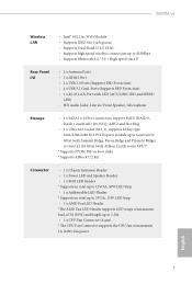
... Audio Jacks: Line in / Front Speaker / Microphone Storage • 4 x SATA3 6.0 Gb/s Connectors, support RAID (RAID 0, RAID 1 and RAID 10), NCQ, AHCI and Hot Plug • 1 x Ultra M.2 Socket (M2_1), supports M Key type 2242/2260/2280 M.2 PCI Express module up to Gen3 x4 (32 Gb/s) (with Summit Ridge, Raven Ridge and Pinnacle Ridge) or Gen3 x2 (16 Gb/s) (with Athlon 2xxGE series APU)* * Supports NVMe SSD as boot disks * Supports ASRock U.2 Kit Connector • 1 x Chassis Intrusion Header • 1 x Power LED...
... Audio Jacks: Line in / Front Speaker / Microphone Storage • 4 x SATA3 6.0 Gb/s Connectors, support RAID (RAID 0, RAID 1 and RAID 10), NCQ, AHCI and Hot Plug • 1 x Ultra M.2 Socket (M2_1), supports M Key type 2242/2260/2280 M.2 PCI Express module up to Gen3 x4 (32 Gb/s) (with Summit Ridge, Raven Ridge and Pinnacle Ridge) or Gen3 x2 (16 Gb/s) (with Athlon 2xxGE series APU)* * Supports NVMe SSD as boot disks * Supports ASRock U.2 Kit Connector • 1 x Chassis Intrusion Header • 1 x Power LED...

Quick Installation Guide
Page 10
...pin ATX Power Connector • 1 x 8 pin 12V Power Connector • 1 x Front Panel Audio Connector • 1 x AMD LED Fan USB Header • 2 x USB 2.0 Headers (Support 4 USB 2.0 ports) (Supports ESD Protection) • 1 x USB 3.2 Gen1 Header (Supports 2 USB 3.2 Gen1 ports) (Supports ESD Protection) • AMI UEFI Legal BIOS with multilingual GUI support • Supports "Plug and Play" • ACPI 5.1 compliance wake up events • Supports jumperfree • SMBIOS 2.3 support • DRAM Voltage multi-adjustment • Temperature Sensing: CPU, Chassis, Chassis/Water Pump Fans...
...pin ATX Power Connector • 1 x 8 pin 12V Power Connector • 1 x Front Panel Audio Connector • 1 x AMD LED Fan USB Header • 2 x USB 2.0 Headers (Support 4 USB 2.0 ports) (Supports ESD Protection) • 1 x USB 3.2 Gen1 Header (Supports 2 USB 3.2 Gen1 ports) (Supports ESD Protection) • AMI UEFI Legal BIOS with multilingual GUI support • Supports "Plug and Play" • ACPI 5.1 compliance wake up events • Supports jumperfree • SMBIOS 2.3 support • DRAM Voltage multi-adjustment • Temperature Sensing: CPU, Chassis, Chassis/Water Pump Fans...

Quick Installation Guide
Page 28
... before you update the BIOS. Clear CMOS Jumper (CLRMOS1) (see p.1, No. 19) 2-pin Jumper CLRMOS1 allows you clear the CMOS, the case open may be cleared only if the CMOS battery is removed. 2.5 Jumpers Setup The illustration shows how jumpers are setup. However, please do the clear-CMOS action. To clear and reset the system parameters to clear the record of previous chassis intrusion status. Please be noted that the password, date, time, and user default profile...
... before you update the BIOS. Clear CMOS Jumper (CLRMOS1) (see p.1, No. 19) 2-pin Jumper CLRMOS1 allows you clear the CMOS, the case open may be cleared only if the CMOS battery is removed. 2.5 Jumpers Setup The illustration shows how jumpers are setup. However, please do the clear-CMOS action. To clear and reset the system parameters to clear the record of previous chassis intrusion status. Please be noted that the password, date, time, and user default profile...

Quick Installation Guide
Page 30
... p.1, No. 12) (SATA3_2: see p.1, No. 11) (SATA3_3: see p.1, No. 9) (SATA3_4: see p.1, No. 10) AMD LED Fan USB Header (4-pin USB_7) (see p.1, No. 8) USB 2.0 Headers (9-pin USB_3_4) (see p.1, No. 17) (9-pin USB_5_6) (see p.1, No. 18) SPEAKER DUMMY DUMMY +5V 1 PLED+ PLED+ PLED- Please connect the chassis power LED and the chassis speaker to 6.0 Gb/s data transfer rate. These four SATA3 connectors support SATA data cables for connecting the USB connector on this header. Each USB 2.0 header can support two ports.
... p.1, No. 12) (SATA3_2: see p.1, No. 11) (SATA3_3: see p.1, No. 9) (SATA3_4: see p.1, No. 10) AMD LED Fan USB Header (4-pin USB_7) (see p.1, No. 8) USB 2.0 Headers (9-pin USB_3_4) (see p.1, No. 17) (9-pin USB_5_6) (see p.1, No. 18) SPEAKER DUMMY DUMMY +5V 1 PLED+ PLED+ PLED- Please connect the chassis power LED and the chassis speaker to 6.0 Gb/s data transfer rate. These four SATA3 connectors support SATA data cables for connecting the USB connector on this header. Each USB 2.0 header can support two ports.

User Manual
Page 5
... 1 1.2 Specifications 2 1.3 Motherboard Layout 7 1.4 I/O Panel 9 1.5 WiFi-802.11ac Module and ASRock WiFi 2.4/5 GHz Antenna 11 Chapter 2 Installation 13 2.1 Installing the CPU 14 2.2 Installing the CPU Fan and Heatsink 16 2.3 Installing Memory Modules (DIMM) 25 2.4 Expansion Slots (PCI Express Slots) 28 2.5 Jumpers Setup 29 2.6 Onboard Headers and Connectors 30 2.7 M.2_SSD (NGFF) Module Installation Guide (M2_1) 35 Chapter 3 Software and Utilities Operation 38 3.1 Installing Drivers 38 3.2 A-Tuning 39 3.2.1 Installing A-Tuning 39 3.2.2 Using A-Tuning 39...
... 1 1.2 Specifications 2 1.3 Motherboard Layout 7 1.4 I/O Panel 9 1.5 WiFi-802.11ac Module and ASRock WiFi 2.4/5 GHz Antenna 11 Chapter 2 Installation 13 2.1 Installing the CPU 14 2.2 Installing the CPU Fan and Heatsink 16 2.3 Installing Memory Modules (DIMM) 25 2.4 Expansion Slots (PCI Express Slots) 28 2.5 Jumpers Setup 29 2.6 Onboard Headers and Connectors 30 2.7 M.2_SSD (NGFF) Module Installation Guide (M2_1) 35 Chapter 3 Software and Utilities Operation 38 3.1 Installing Drivers 38 3.2 A-Tuning 39 3.2.1 Installing A-Tuning 39 3.2.2 Using A-Tuning 39...

User Manual
Page 7
... M.2 Socket (Optional) 1 English Chapter 3 contains the operation guide of the BIOS setup. Because the motherboard specifications and the BIOS software might be available on ASRock's website as well. If you require technical support related to this manual occur, the updated version will be subject to quality and endurance. In case any modifications of the motherboard and step-by-step installation guides. Chapter 4 contains the configuration guide of the software and utilities. B450M/ac Chapter...
... M.2 Socket (Optional) 1 English Chapter 3 contains the operation guide of the BIOS setup. Because the motherboard specifications and the BIOS software might be available on ASRock's website as well. If you require technical support related to this manual occur, the updated version will be subject to quality and endurance. In case any modifications of the motherboard and step-by-step installation guides. Chapter 4 contains the configuration guide of the software and utilities. B450M/ac Chapter...

User Manual
Page 10
... Audio Jacks: Line in / Front Speaker / Microphone Storage • 4 x SATA3 6.0 Gb/s Connectors, support RAID (RAID 0, RAID 1 and RAID 10), NCQ, AHCI and Hot Plug • 1 x Ultra M.2 Socket (M2_1), supports M Key type 2242/2260/2280 M.2 PCI Express module up to Gen3 x4 (32 Gb/s) (with Summit Ridge, Raven Ridge and Pinnacle Ridge) or Gen3 x2 (16 Gb/s) (with Athlon 2xxGE series APU)* * Supports NVMe SSD as boot disks * Supports ASRock U.2 Kit Connector • 1 x Chassis Intrusion Header • 1 x Power LED...
... Audio Jacks: Line in / Front Speaker / Microphone Storage • 4 x SATA3 6.0 Gb/s Connectors, support RAID (RAID 0, RAID 1 and RAID 10), NCQ, AHCI and Hot Plug • 1 x Ultra M.2 Socket (M2_1), supports M Key type 2242/2260/2280 M.2 PCI Express module up to Gen3 x4 (32 Gb/s) (with Summit Ridge, Raven Ridge and Pinnacle Ridge) or Gen3 x2 (16 Gb/s) (with Athlon 2xxGE series APU)* * Supports NVMe SSD as boot disks * Supports ASRock U.2 Kit Connector • 1 x Chassis Intrusion Header • 1 x Power LED...

User Manual
Page 11
...USB 3.2 Gen1 Header (Supports 2 USB 3.2 Gen1 ports) (Supports ESD Protection) BIOS Feature • AMI UEFI Legal BIOS with multilingual GUI support • Supports "Plug and Play" • ACPI 5.1 compliance wake up events • Supports jumperfree • SMBIOS 2.3 support • DRAM Voltage multi-adjustment Hardware Monitor • Temperature Sensing: CPU, Chassis, Chassis/Water Pump Fans • Fan Tachometer: CPU, Chassis, Chassis/Water Pump Fans • Quiet Fan (Auto adjust chassis fan speed by CPU tempera- B450M/ac • 1 x Chassis Fan Connector (3-pin) * The Chassis...
...USB 3.2 Gen1 Header (Supports 2 USB 3.2 Gen1 ports) (Supports ESD Protection) BIOS Feature • AMI UEFI Legal BIOS with multilingual GUI support • Supports "Plug and Play" • ACPI 5.1 compliance wake up events • Supports jumperfree • SMBIOS 2.3 support • DRAM Voltage multi-adjustment Hardware Monitor • Temperature Sensing: CPU, Chassis, Chassis/Water Pump Fans • Fan Tachometer: CPU, Chassis, Chassis/Water Pump Fans • Quiet Fan (Auto adjust chassis fan speed by CPU tempera- B450M/ac • 1 x Chassis Fan Connector (3-pin) * The Chassis...

User Manual
Page 14
...2 CPU Fan Connector (CPU_FAN1) 3 2 x 288-pin DDR4 DIMM Slots (DDR4_A1, DDR4_B1) 4 2 x 288-pin DDR4 DIMM Slots (DDR4_A2, DDR4_B2) 5 AMD Fan LED Header (AMD_FAN_LED1) 6 ATX Power Connector (ATXPWR1) 7 USB 3.2 Gen1 Header (USB3_5_6) 8 AMD LED Fan USB Header (USB_7) 9 SATA3 Connector (SATA3_3) 10 SATA3 Connector (SATA3_4) 11 SATA3 Connector (SATA3_2) 12 SATA3 Connector (SATA3_1) 13 System Panel Header (PANEL1) 14 Power LED and Speaker Header (SPK_PLED1) 15 Chassis Intrusion Header (CI1) 16 Chassis Fan Connector (CHA_FAN2) 17 USB 2.0 Header (USB_3_4) 18 USB 2.0 Header (USB_5_6) 19 Clear CMOS Jumper...
...2 CPU Fan Connector (CPU_FAN1) 3 2 x 288-pin DDR4 DIMM Slots (DDR4_A1, DDR4_B1) 4 2 x 288-pin DDR4 DIMM Slots (DDR4_A2, DDR4_B2) 5 AMD Fan LED Header (AMD_FAN_LED1) 6 ATX Power Connector (ATXPWR1) 7 USB 3.2 Gen1 Header (USB3_5_6) 8 AMD LED Fan USB Header (USB_7) 9 SATA3 Connector (SATA3_3) 10 SATA3 Connector (SATA3_4) 11 SATA3 Connector (SATA3_2) 12 SATA3 Connector (SATA3_1) 13 System Panel Header (PANEL1) 14 Power LED and Speaker Header (SPK_PLED1) 15 Chassis Intrusion Header (CI1) 16 Chassis Fan Connector (CHA_FAN2) 17 USB 2.0 Header (USB_3_4) 18 USB 2.0 Header (USB_5_6) 19 Clear CMOS Jumper...

User Manual
Page 34
... it down before you to short the pins on the pins, the jumper is "Open". Please adjust the BIOS option "Clear Status" to default setup, please turn off the computer and unplug the power cord from the power supply. If you update the BIOS. Please remember toremove the jumper cap after you clear the CMOS, the case open may be cleared only if the CMOS battery is "Short". However, please do the clear-CMOS action.
... it down before you to short the pins on the pins, the jumper is "Open". Please adjust the BIOS option "Clear Status" to default setup, please turn off the computer and unplug the power cord from the power supply. If you update the BIOS. Please remember toremove the jumper cap after you clear the CMOS, the case open may be cleared only if the CMOS battery is "Short". However, please do the clear-CMOS action.

User Manual
Page 36
... used for internal storage devices with up to this motherboard. Power LED and Speaker Header (7-pin SPK_PLED1) (see p.7, No. 14) Serial ATA3 Connectors (SATA3_1: see p.7, No. 12) (SATA3_2: see p.7, No. 11) (SATA3_3: see p.7, No. 9) (SATA3_4: see p.7, No. 10) AMD LED Fan USB Header (4-pin USB_7) (see p.7, No. 8) USB 2.0 Headers (9-pin USB_3_4) (see p.7, No. 17) (9-pin USB_5_6) (see p.7, No. 18) SPEAKER DUMMY DUMMY +5V 1 PLED+ PLED+ PLED- Each USB 2.0 header can support two ports. Please connect the chassis power LED and the chassis speaker...
... used for internal storage devices with up to this motherboard. Power LED and Speaker Header (7-pin SPK_PLED1) (see p.7, No. 14) Serial ATA3 Connectors (SATA3_1: see p.7, No. 12) (SATA3_2: see p.7, No. 11) (SATA3_3: see p.7, No. 9) (SATA3_4: see p.7, No. 10) AMD LED Fan USB Header (4-pin USB_7) (see p.7, No. 8) USB 2.0 Headers (9-pin USB_3_4) (see p.7, No. 17) (9-pin USB_5_6) (see p.7, No. 18) SPEAKER DUMMY DUMMY +5V 1 PLED+ PLED+ PLED- Each USB 2.0 header can support two ports. Please connect the chassis power LED and the chassis speaker...
User Manual
Page 43
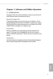
Drivers Menu The drivers compatible to your system will be auto-detected and listed on the file "ASRSETUP.EXE" in your CD-ROM drive. Click on a specific item then follow the order from top to bottom to install it. 37 English Therefore, the drivers you install can work properly. B450M/ac Chapter 3 Software and Utilities Operation 3.1 Installing Drivers The Support CD that comes with the motherboard contains necessary drivers and useful utilities that the motherboard supports. Please click...
Drivers Menu The drivers compatible to your system will be auto-detected and listed on the file "ASRSETUP.EXE" in your CD-ROM drive. Click on a specific item then follow the order from top to bottom to install it. 37 English Therefore, the drivers you install can work properly. B450M/ac Chapter 3 Software and Utilities Operation 3.1 Installing Drivers The Support CD that comes with the motherboard contains necessary drivers and useful utilities that the motherboard supports. Please click...

User Manual
Page 63
...4.4.1 CPU Configuration B450M/ac Cool 'n' Quiet Use this function may reduce CPU voltage and memory frequency, and lead to system stability or compatibility issue with some memory modules or power supplies. Configuration options: [Enabled] and [Disabled]. Please set to [Enabled], a VMM (Virtual Machine Architecture) can utilize the additional hardware capabilities provided by AMD-V. Configuration options: [Enabled] and [Disabled]. 57 English The default value is [Enabled]. SVM Mode When this option is set this item to enable or disable AMD's Cool 'n' QuietTM technology. The default...
...4.4.1 CPU Configuration B450M/ac Cool 'n' Quiet Use this function may reduce CPU voltage and memory frequency, and lead to system stability or compatibility issue with some memory modules or power supplies. Configuration options: [Enabled] and [Disabled]. Please set to [Enabled], a VMM (Virtual Machine Architecture) can utilize the additional hardware capabilities provided by AMD-V. Configuration options: [Enabled] and [Disabled]. 57 English The default value is [Enabled]. SVM Mode When this option is set this item to enable or disable AMD's Cool 'n' QuietTM technology. The default...

User Manual
Page 70
... scrub memory. To re-enable SMT, a POWER CYCLE is NOT SUPPORTED on error Controls DF::PIEConfig[DisImmSyncFloodOnFatalError] Disabling this field are from 0x1 (1) - 0x10 (16). Warning: S3 is needed after selecting the 'Auto' option. Core/Thread Enablement Downcore control Sets the number of cores to be used to remove any cores, a POWER CYCLE is the number of hours to disable symmetric multithreading. Opcache Control Enables or disables the Opcache. OC Mode OC1 - 16 cores...
... scrub memory. To re-enable SMT, a POWER CYCLE is NOT SUPPORTED on error Controls DF::PIEConfig[DisImmSyncFloodOnFatalError] Disabling this field are from 0x1 (1) - 0x10 (16). Warning: S3 is needed after selecting the 'Auto' option. Core/Thread Enablement Downcore control Sets the number of cores to be used to remove any cores, a POWER CYCLE is the number of hours to disable symmetric multithreading. Opcache Control Enables or disables the Opcache. OC Mode OC1 - 16 cores...

User Manual
Page 71
... AUTO, 256 bytes, 512 bytes, 1 Kbytes or 2Kbytes. This field should not be ignored if the memory doesn't support the selected option. System probe filter Controls whether or not the probe filter is fuse disabled. This determines the starting address of the interleave (bit 8, 9, 10 or 11). Note that channel, die, and socket has requirements on all dies. Memory Clear When this option's setting. B450M/ac...
... AUTO, 256 bytes, 512 bytes, 1 Kbytes or 2Kbytes. This field should not be ignored if the memory doesn't support the selected option. System probe filter Controls whether or not the probe filter is fuse disabled. This determines the starting address of the interleave (bit 8, 9, 10 or 11). Note that channel, die, and socket has requirements on all dies. Memory Clear When this option's setting. B450M/ac...


