
RAID Installation Guide
Page 8
... download the "SATA Floppy Imaged driver" from ASRock's website A. B. A. C. Go to enter UEFI setup utility. Follow instructions to finish the configuration. During Windows installation process, when Disk selection page show up, please click . Please install the DVD-ROM. Plug a USB drive into the DVD-ROM drive. Click to find the driver inside your USB flash disk. D. STEP 3.1: Copy RAID driver to a USB flash drive You can choose either STEP 3.1 or STEP 3.2 to finish the driver copy process. STEP 3.2: Download driver from ASRock's website and unzip the file...
... download the "SATA Floppy Imaged driver" from ASRock's website A. B. A. C. Go to enter UEFI setup utility. Follow instructions to finish the configuration. During Windows installation process, when Disk selection page show up, please click . Please install the DVD-ROM. Plug a USB drive into the DVD-ROM drive. Click to find the driver inside your USB flash disk. D. STEP 3.1: Copy RAID driver to a USB flash drive You can choose either STEP 3.1 or STEP 3.2 to finish the driver copy process. STEP 3.2: Download driver from ASRock's website and unzip the file...

RAID Installation Guide
Page 12
Click to save to enter UEFI setup utility. Please install the DVD-ROM. Please download the "SATA Floppy Imaged driver" from ASRock's website A. During system boot, press or key to exit. Plug a USB drive into your USB flash disk. 12 Follow instructions to Tools Easy RAID Installer F. D. STEP 2.2: Download driver from ASRock's website and unzip the file into one of the USB port. Go to finish the driver copy process. H. STEP 2.1: Copy RAID driver to a USB flash drive You can choose either STEP2.1 or STEP2...
Click to save to enter UEFI setup utility. Please install the DVD-ROM. Please download the "SATA Floppy Imaged driver" from ASRock's website A. During system boot, press or key to exit. Plug a USB drive into your USB flash disk. 12 Follow instructions to Tools Easy RAID Installer F. D. STEP 2.2: Download driver from ASRock's website and unzip the file into one of the USB port. Go to finish the driver copy process. H. STEP 2.1: Copy RAID driver to a USB flash drive You can choose either STEP2.1 or STEP2...

Quick Installation Guide
Page 4
...) 3 AMD Fan LED Header (AMD_FAN_LED1) 4 2 x 288-pin DDR4 DIMM Slots (DDR4_A2, DDR4_B2) 5 CPU/Water Pump Fan Connector (CPU_FAN2/WP) 6 CPU Fan Connector (CPU_FAN1) 7 ATX Power Connector (ATXPWR1) 8 USB 3.1 Gen1 Header (USB3_5_6) 9 SATA3 Connector (SATA3_1) 10 SATA3 Connector (SATA3_2) 11 SATA3 Connector (SATA3_A1) 12 SATA3 Connector (SATA3_A2) 13 SATA3 Connector (SATA3_3) 14 SATA3 Connector (SATA3_4) 15 System Panel Header (PANEL1) 16 Power LED and Speaker Header (SPK_PLED1) 17 Chassis/Water Pump Fan Connector (CHA_FAN3/WP) 18 Chassis/Water Pump Fan Connector (CHA_FAN2/WP) 19 Clear CMOS Jumper...
...) 3 AMD Fan LED Header (AMD_FAN_LED1) 4 2 x 288-pin DDR4 DIMM Slots (DDR4_A2, DDR4_B2) 5 CPU/Water Pump Fan Connector (CPU_FAN2/WP) 6 CPU Fan Connector (CPU_FAN1) 7 ATX Power Connector (ATXPWR1) 8 USB 3.1 Gen1 Header (USB3_5_6) 9 SATA3 Connector (SATA3_1) 10 SATA3 Connector (SATA3_2) 11 SATA3 Connector (SATA3_A1) 12 SATA3 Connector (SATA3_A2) 13 SATA3 Connector (SATA3_3) 14 SATA3 Connector (SATA3_4) 15 System Panel Header (PANEL1) 16 Power LED and Speaker Header (SPK_PLED1) 17 Chassis/Water Pump Fan Connector (CHA_FAN3/WP) 18 Chassis/Water Pump Fan Connector (CHA_FAN2/WP) 19 Clear CMOS Jumper...
Quick Installation Guide
Page 7
... BIOS software might be updated, the content of this motherboard, please visit our website for specific information about the model you are using. ASRock website http://www.asrock.com. 1.1 Package Contents • ASRock B450 Steel Legend Motherboard (ATX Form Factor) • ASRock B450 Steel Legend Quick Installation Guide • ASRock B450 Steel Legend Support CD • 1 x I/O Panel Shield • 2 x Serial ATA (SATA) Data Cables (Optional) • 2 x Screws for M.2 Sockets (Optional) • 1 x Standoff for purchasing ASRock B450 Steel Legend motherboard, a reliable motherboard...
... BIOS software might be updated, the content of this motherboard, please visit our website for specific information about the model you are using. ASRock website http://www.asrock.com. 1.1 Package Contents • ASRock B450 Steel Legend Motherboard (ATX Form Factor) • ASRock B450 Steel Legend Quick Installation Guide • ASRock B450 Steel Legend Support CD • 1 x I/O Panel Shield • 2 x Serial ATA (SATA) Data Cables (Optional) • 2 x Screws for M.2 Sockets (Optional) • 1 x Standoff for purchasing ASRock B450 Steel Legend motherboard, a reliable motherboard...

Quick Installation Guide
Page 11
... CHA_FAN3/WP can auto detect if 3-pin or 4-pin fan is in use. • 1 x 24 pin ATX Power Connector • 1 x 8 pin 12V Power Connector • 1 x Front Panel Audio Connector • 2 x USB 2.0 Headers (Support 4 USB 2.0 ports) (Supports ESD Protection) • 1 x USB 3.1 Gen1 Header (Supports 2 USB 3.1 Gen1 ports) (Supports ESD Protection) BIOS Feature • AMI UEFI Legal BIOS with multilingual GUI support • Supports "Plug and Play" • ACPI 5.1 compliance wake up events • Supports jumperfree • SMBIOS 2.3 support • DRAM Voltage multi-adjustment English...
... CHA_FAN3/WP can auto detect if 3-pin or 4-pin fan is in use. • 1 x 24 pin ATX Power Connector • 1 x 8 pin 12V Power Connector • 1 x Front Panel Audio Connector • 2 x USB 2.0 Headers (Support 4 USB 2.0 ports) (Supports ESD Protection) • 1 x USB 3.1 Gen1 Header (Supports 2 USB 3.1 Gen1 ports) (Supports ESD Protection) BIOS Feature • AMI UEFI Legal BIOS with multilingual GUI support • Supports "Plug and Play" • ACPI 5.1 compliance wake up events • Supports jumperfree • SMBIOS 2.3 support • DRAM Voltage multi-adjustment English...

Quick Installation Guide
Page 27
... hardware settings for PCI Express x16 lane width graphics cards. PCIe slots: PCIE1 (PCIe 3.0 x16 slot) is used for PCI Express x1 lane width cards. PCIE3 (PCIe 2.0 x1 slot) is occupied, PCIE4 will be disabled. PCIe Slot Configurations Ryzen Series CPUs (Pinnacle Ridge) Ryzen Series CPUs (Summit Ridge) Ryzen Series CPUs (Raven Ridge) Athlon series CPUs PCIE1 x16 x16 x8 x4 PCIE4 x4 x4 x4 x2 For a better thermal environment, please connect a chassis fan to the motherboard's chassis fan connector...
... hardware settings for PCI Express x16 lane width graphics cards. PCIe slots: PCIE1 (PCIe 3.0 x16 slot) is used for PCI Express x1 lane width cards. PCIE3 (PCIe 2.0 x1 slot) is occupied, PCIE4 will be disabled. PCIe Slot Configurations Ryzen Series CPUs (Pinnacle Ridge) Ryzen Series CPUs (Summit Ridge) Ryzen Series CPUs (Raven Ridge) Athlon series CPUs PCIE1 x16 x16 x8 x4 PCIE4 x4 x4 x4 x2 For a better thermal environment, please connect a chassis fan to the motherboard's chassis fan connector...

Quick Installation Guide
Page 30
...) (SATA3_A2: see p.1 or 8, No. 8) USB_PWR PP+ GND DUMMY 1 GND P+ PUSB_PWR There are two headers on this motherboard. SATA3_2 SATA3_1 Please connect the chassis power LED and the chassis speaker to 6.0 Gb/s data transfer rate. * M2_2, SATA3_3 and SATA3_4 share lanes. If either one header on this header. These six SATA3 connectors support SATA data cables for internal storage devices with up to this motherboard. Each USB 3.1 Gen1 header can support two ports.
...) (SATA3_A2: see p.1 or 8, No. 8) USB_PWR PP+ GND DUMMY 1 GND P+ PUSB_PWR There are two headers on this motherboard. SATA3_2 SATA3_1 Please connect the chassis power LED and the chassis speaker to 6.0 Gb/s data transfer rate. * M2_2, SATA3_3 and SATA3_4 share lanes. If either one header on this header. These six SATA3 connectors support SATA data cables for internal storage devices with up to this motherboard. Each USB 3.1 Gen1 header can support two ports.

User Manual
Page 4
...Contents 1 1.2 Specifications 2 1.3 Motherboard Layout 7 1.4 I/O Panel 9 Chapter 2 Installation 11 2.1 Installing the CPU 12 2.2 Installing the CPU Fan and Heatsink 14 2.3 Installing Memory Modules (DIMM) 22 2.4 Expansion Slots (PCI Express Slots) 25 2.5 Jumpers Setup 26 2.6 Onboard Headers and Connectors 27 2.7 CrossFireXTM and Quad CrossFireXTM Operation Guide 32 2.7.1 Installing Two CrossFireXTM-Ready Graphics Cards 32 2.7.2 Driver Installation and Setup 34 2.8 M.2_SSD (NGFF) Module Installation Guide (M2_1) 35 2.9 M.2_SSD (NGFF) Module Installation Guide (M2_2...
...Contents 1 1.2 Specifications 2 1.3 Motherboard Layout 7 1.4 I/O Panel 9 Chapter 2 Installation 11 2.1 Installing the CPU 12 2.2 Installing the CPU Fan and Heatsink 14 2.3 Installing Memory Modules (DIMM) 22 2.4 Expansion Slots (PCI Express Slots) 25 2.5 Jumpers Setup 26 2.6 Onboard Headers and Connectors 27 2.7 CrossFireXTM and Quad CrossFireXTM Operation Guide 32 2.7.1 Installing Two CrossFireXTM-Ready Graphics Cards 32 2.7.2 Driver Installation and Setup 34 2.8 M.2_SSD (NGFF) Module Installation Guide (M2_1) 35 2.9 M.2_SSD (NGFF) Module Installation Guide (M2_2...
User Manual
Page 7
...ATX Form Factor) • ASRock B450 Steel Legend Quick Installation Guide • ASRock B450 Steel Legend Support CD • 1 x I/O Panel Shield • 2 x Serial ATA (SATA) Data Cables (Optional) • 2 x Screws for M.2 Sockets (Optional) • 1 x Standoff for M.2 Socket (Optional) 1 English In this manual will be subject to quality and endurance. Chapter 3 contains the operation guide of the motherboard and step-by-step installation guides. Chapter 4 contains the configuration guide of the BIOS setup. You may find the latest VGA cards and CPU support list on ASRock...
...ATX Form Factor) • ASRock B450 Steel Legend Quick Installation Guide • ASRock B450 Steel Legend Support CD • 1 x I/O Panel Shield • 2 x Serial ATA (SATA) Data Cables (Optional) • 2 x Screws for M.2 Sockets (Optional) • 1 x Standoff for M.2 Socket (Optional) 1 English In this manual will be subject to quality and endurance. Chapter 3 contains the operation guide of the motherboard and step-by-step installation guides. Chapter 4 contains the configuration guide of the BIOS setup. You may find the latest VGA cards and CPU support list on ASRock...

User Manual
Page 11
... CHA_FAN3/WP can auto detect if 3-pin or 4-pin fan is in use. • 1 x 24 pin ATX Power Connector • 1 x 8 pin 12V Power Connector • 1 x Front Panel Audio Connector • 2 x USB 2.0 Headers (Support 4 USB 2.0 ports) (Supports ESD Protection) • 1 x USB 3.1 Gen1 Header (Supports 2 USB 3.1 Gen1 ports) (Supports ESD Protection) BIOS Feature • AMI UEFI Legal BIOS with multilingual GUI support • Supports "Plug and Play" • ACPI 5.1 compliance wake up events • Supports jumperfree • SMBIOS 2.3 support • DRAM Voltage multi-adjustment English...
... CHA_FAN3/WP can auto detect if 3-pin or 4-pin fan is in use. • 1 x 24 pin ATX Power Connector • 1 x 8 pin 12V Power Connector • 1 x Front Panel Audio Connector • 2 x USB 2.0 Headers (Support 4 USB 2.0 ports) (Supports ESD Protection) • 1 x USB 3.1 Gen1 Header (Supports 2 USB 3.1 Gen1 ports) (Supports ESD Protection) BIOS Feature • AMI UEFI Legal BIOS with multilingual GUI support • Supports "Plug and Play" • ACPI 5.1 compliance wake up events • Supports jumperfree • SMBIOS 2.3 support • DRAM Voltage multi-adjustment English...

User Manual
Page 14
...) 3 AMD Fan LED Header (AMD_FAN_LED1) 4 2 x 288-pin DDR4 DIMM Slots (DDR4_A2, DDR4_B2) 5 CPU/Water Pump Fan Connector (CPU_FAN2/WP) 6 CPU Fan Connector (CPU_FAN1) 7 ATX Power Connector (ATXPWR1) 8 USB 3.1 Gen1 Header (USB3_5_6) 9 SATA3 Connector (SATA3_1) 10 SATA3 Connector (SATA3_2) 11 SATA3 Connector (SATA3_A1) 12 SATA3 Connector (SATA3_A2) 13 SATA3 Connector (SATA3_3) 14 SATA3 Connector (SATA3_4) 15 System Panel Header (PANEL1) 16 Power LED and Speaker Header (SPK_PLED1) 17 Chassis/Water Pump Fan Connector (CHA_FAN3/WP) 18 Chassis/Water Pump Fan Connector (CHA_FAN2/WP) 19 Clear CMOS Jumper...
...) 3 AMD Fan LED Header (AMD_FAN_LED1) 4 2 x 288-pin DDR4 DIMM Slots (DDR4_A2, DDR4_B2) 5 CPU/Water Pump Fan Connector (CPU_FAN2/WP) 6 CPU Fan Connector (CPU_FAN1) 7 ATX Power Connector (ATXPWR1) 8 USB 3.1 Gen1 Header (USB3_5_6) 9 SATA3 Connector (SATA3_1) 10 SATA3 Connector (SATA3_2) 11 SATA3 Connector (SATA3_A1) 12 SATA3 Connector (SATA3_A2) 13 SATA3 Connector (SATA3_3) 14 SATA3 Connector (SATA3_4) 15 System Panel Header (PANEL1) 16 Power LED and Speaker Header (SPK_PLED1) 17 Chassis/Water Pump Fan Connector (CHA_FAN3/WP) 18 Chassis/Water Pump Fan Connector (CHA_FAN2/WP) 19 Clear CMOS Jumper...

User Manual
Page 34
... P+ PUSB_PWR There are two headers on this motherboard. SATA3_2 SATA3_1 Please connect the chassis power LED and the chassis speaker to 6.0 Gb/s data transfer rate. * M2_2, SATA3_3 and SATA3_4 share lanes. Each USB 3.1 Gen1 header can support two ports. If either one of them is one header on this header. Each USB 2.0 header can support two ports. 28 English Power LED and Speaker Header (7-pin SPK_PLED1) (see p.7, No. 16) Serial ATA3 Connectors (SATA3_1: see p.7, No...
... P+ PUSB_PWR There are two headers on this motherboard. SATA3_2 SATA3_1 Please connect the chassis power LED and the chassis speaker to 6.0 Gb/s data transfer rate. * M2_2, SATA3_3 and SATA3_4 share lanes. Each USB 3.1 Gen1 header can support two ports. If either one of them is one header on this header. Each USB 2.0 header can support two ports. 28 English Power LED and Speaker Header (7-pin SPK_PLED1) (see p.7, No. 16) Serial ATA3 Connectors (SATA3_1: see p.7, No...

User Manual
Page 38
2.7 CrossFireXTM and Quad CrossFireXTM Operation Guide This motherboard supports CrossFireXTM and Quad CrossFireXTM that the cards are AMD certified. 2. Download the drivers from the AMD's website: www.amd.com 3. Please refer to the AMD's website for detailed installation guide. 2.7.1 Installing Two CrossFireXTM-Ready Graphics Cards Step 1 Insert one graphics card into PCIE1 slot and the other graphics card to use identical CrossFireXTM-ready graphics cards that your power supply unit (PSU) can provide at least the...
2.7 CrossFireXTM and Quad CrossFireXTM Operation Guide This motherboard supports CrossFireXTM and Quad CrossFireXTM that the cards are AMD certified. 2. Download the drivers from the AMD's website: www.amd.com 3. Please refer to the AMD's website for detailed installation guide. 2.7.1 Installing Two CrossFireXTM-Ready Graphics Cards Step 1 Insert one graphics card into PCIE1 slot and the other graphics card to use identical CrossFireXTM-ready graphics cards that your power supply unit (PSU) can provide at least the...
User Manual
Page 40
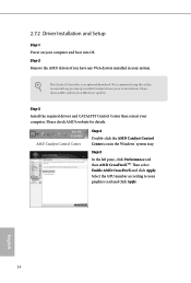
... 2 Remove the AMD drivers if you have any previously installed Catalyst drivers prior to uninstall any VGA drivers installed in the Windows® system tray. Step 3 Install the required drivers and CATALYST Control Center then restart your graphics card and click Apply. AMD Catalyst Control Center Step 4 Double-click the AMD Catalyst Control Center icon in your computer and boot into OS. We recommend using this utility to installation. 2.7.2 Driver Installation and Setup Step 1 Power on...
... 2 Remove the AMD drivers if you have any previously installed Catalyst drivers prior to uninstall any VGA drivers installed in the Windows® system tray. Step 3 Install the required drivers and CATALYST Control Center then restart your graphics card and click Apply. AMD Catalyst Control Center Step 4 Double-click the AMD Catalyst Control Center icon in your computer and boot into OS. We recommend using this utility to installation. 2.7.2 Driver Installation and Setup Step 1 Power on...
User Manual
Page 47
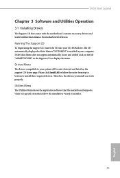
Drivers Menu The drivers compatible to display the menu. Click on the file "ASRSETUP.EXE" in your computer. If the Main Menu does not appear automatically, locate and double click on a specific item then follow the order from top to bottom to install it. 41 English Utilities Menu The Utilities Menu shows the application software that enhance the motherboard's features. B450 Steel Legend Chapter 3 Software and Utilities Operation 3.1 Installing Drivers The Support CD that comes with the...
Drivers Menu The drivers compatible to display the menu. Click on the file "ASRSETUP.EXE" in your computer. If the Main Menu does not appear automatically, locate and double click on a specific item then follow the order from top to bottom to install it. 41 English Utilities Menu The Utilities Menu shows the application software that enhance the motherboard's features. B450 Steel Legend Chapter 3 Software and Utilities Operation 3.1 Installing Drivers The Support CD that comes with the...

User Manual
Page 63
... overclock mode. CPU Frequency and Voltage Change If this item is not supported on your screen. To re-enable SMT, a power cycle is disabled. 57 English Warning: S3 is set to [Manual], the multiplier and voltage will be used to disable symmetric multithreading. 4.3 OC Tweaker Screen In the OC Tweaker screen, you see on systems where SMT is needed after selecting [Auto]. B450 Steel Legend Because the UEFI software is constantly being updated, the following UEFI setup screens...
... overclock mode. CPU Frequency and Voltage Change If this item is not supported on your screen. To re-enable SMT, a power cycle is disabled. 57 English Warning: S3 is set to [Manual], the multiplier and voltage will be used to disable symmetric multithreading. 4.3 OC Tweaker Screen In the OC Tweaker screen, you see on systems where SMT is needed after selecting [Auto]. B450 Steel Legend Because the UEFI software is constantly being updated, the following UEFI setup screens...

User Manual
Page 71
PS2 Y-Cable Enable the PS2 Y-Cable or set this option to Auto. 65 English 4.4.5 Super IO Configuration B450 Steel Legend Serial Port Enable or disable the Serial port. Serial Port Address Select the address of the Serial port.
PS2 Y-Cable Enable the PS2 Y-Cable or set this option to Auto. 65 English 4.4.5 Super IO Configuration B450 Steel Legend Serial Port Enable or disable the Serial port. Serial Port Address Select the address of the Serial port.

User Manual
Page 75
... propagation Control DF::PIEConfig[DisSyncFloodProp]. B450 Steel Legend Opcache Control Enables or disables the Opcache. Freeze DF module queues on systems where SMT is disabled. SMTEN This item can be used to remove any cores, a POWER CYCLE is needed after selecting the 'Auto' option. Once this option sets DF:PIEConfig[DisImmSyncFloodOnFatalError]. 69 English Warning: S3 is the number of cores to take effect. OC Mode OC1 - 16 cores/3.6GHz...
... propagation Control DF::PIEConfig[DisSyncFloodProp]. B450 Steel Legend Opcache Control Enables or disables the Opcache. Freeze DF module queues on systems where SMT is disabled. SMTEN This item can be used to remove any cores, a POWER CYCLE is needed after selecting the 'Auto' option. Once this option sets DF:PIEConfig[DisImmSyncFloodOnFatalError]. 69 English Warning: S3 is the number of cores to take effect. OC Mode OC1 - 16 cores/3.6GHz...
User Manual
Page 83
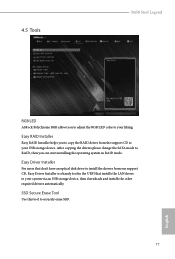
... your USB storage device. 4.5 Tools B450 Steel Legend RGB LED ASRock Polychrome RGB allows you can start installing the operating system in the UEFI that don't have an optical disk drive to install the drivers from the support CD to securely erase SSD. 77 English Easy Driver Installer For users that installs the LAN driver to your system via an USB storage device, then downloads and installs the other required drivers automatically. After copying the drivers please change the SATA mode to RAID...
... your USB storage device. 4.5 Tools B450 Steel Legend RGB LED ASRock Polychrome RGB allows you can start installing the operating system in the UEFI that don't have an optical disk drive to install the drivers from the support CD to securely erase SSD. 77 English Easy Driver Installer For users that installs the LAN driver to your system via an USB storage device, then downloads and installs the other required drivers automatically. After copying the drivers please change the SATA mode to RAID...
User Manual
Page 84
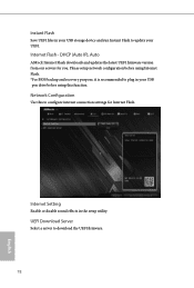
... server to configure internet connection settings for you. DHCP (Auto IP), Auto ASRock Internet Flash downloads and updates the latest UEFI firmware version from our servers for Internet Flash. Please setup network configuration before using Internet Flash. *For BIOS backup and recovery purpose, it is recommended to plug in the setup utility. Internet Flash - Instant Flash Save UEFI files in your USB storage device and run Instant Flash to update your USB pen drive before using this to download the UEFI firmware. 78 English Internet Setting Enable or disable sound effects...
... server to configure internet connection settings for you. DHCP (Auto IP), Auto ASRock Internet Flash downloads and updates the latest UEFI firmware version from our servers for Internet Flash. Please setup network configuration before using Internet Flash. *For BIOS backup and recovery purpose, it is recommended to plug in the setup utility. Internet Flash - Instant Flash Save UEFI files in your USB storage device and run Instant Flash to update your USB pen drive before using this to download the UEFI firmware. 78 English Internet Setting Enable or disable sound effects...


