

User Manual
Page 4
... Contents 1 1.2 Specifications 2 1.3 Motherboard Layout 7 1.4 I/O Panel 9 Chapter 2 Installation 11 2.1 Installing the CPU 12 2.2 Installing the CPU Fan and Heatsink 15 2.3 Installing Memory Modules (DIMM) 16 2.4 Expansion Slots (PCI Express Slots) 18 2.5 Jumpers Setup 19 2.6 Onboard Headers and Connectors 20 2.7 CrossFireXTM and Quad CrossFireXTM Operation Guide 24 2.7.1 Installing Two CrossFireXTM-Ready Graphics Cards 24 2.7.2 Driver Installation and Setup 26 2.8 M.2 WiFi/BT Module and Intel® CNVi (Integrated WiFi/BT) Installation Guide 27 2.9 M.2_SSD...
... Contents 1 1.2 Specifications 2 1.3 Motherboard Layout 7 1.4 I/O Panel 9 Chapter 2 Installation 11 2.1 Installing the CPU 12 2.2 Installing the CPU Fan and Heatsink 15 2.3 Installing Memory Modules (DIMM) 16 2.4 Expansion Slots (PCI Express Slots) 18 2.5 Jumpers Setup 19 2.6 Onboard Headers and Connectors 20 2.7 CrossFireXTM and Quad CrossFireXTM Operation Guide 24 2.7.1 Installing Two CrossFireXTM-Ready Graphics Cards 24 2.7.2 Driver Installation and Setup 26 2.8 M.2 WiFi/BT Module and Intel® CNVi (Integrated WiFi/BT) Installation Guide 27 2.9 M.2_SSD...
User Manual
Page 6
... the introduction of the BIOS setup. In this motherboard, please visit our website for specific information about the model you for M.2 Sockets (Optional) • 1 x I/O Panel Shield 1 English Chapter 4 contains the configuration guide of the motherboard and step-by-step installation guides. Because the motherboard specifications and the BIOS software might be updated, the content of the software and utilities. You may find the latest VGA cards and CPU support list on ASRock's website without notice. Chapter...
... the introduction of the BIOS setup. In this motherboard, please visit our website for specific information about the model you for M.2 Sockets (Optional) • 1 x I/O Panel Shield 1 English Chapter 4 contains the configuration guide of the motherboard and step-by-step installation guides. Because the motherboard specifications and the BIOS software might be updated, the content of the software and utilities. You may find the latest VGA cards and CPU support list on ASRock's website without notice. Chapter...

User Manual
Page 10
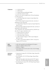
...4-pin fan is in use. • 1 x 24 pin ATX Power Connector • 1 x 8 pin 12V Power Connector • 1 x Front Panel Audio Connector • 2 x USB 2.0 Headers (Support 3 USB 2.0 ports) (Supports ESD Protection) • 1 x USB 3.1 Gen1 Header (Supports 2 USB 3.1 Gen1 ports) (Supports ESD Protection) BIOS Feature • AMI UEFI Legal BIOS with multilingual GUI support • ACPI 6.0 Compliant wake up events • SMBIOS 2.7 Support • CPU, DRAM, PCH 1.0V, VCCIO, VCCSA, VCCST Voltage Multi-adjustment Hardware Monitor • Temperature Sensing: CPU, CPU/Water Pump, Chassis...
...4-pin fan is in use. • 1 x 24 pin ATX Power Connector • 1 x 8 pin 12V Power Connector • 1 x Front Panel Audio Connector • 2 x USB 2.0 Headers (Support 3 USB 2.0 ports) (Supports ESD Protection) • 1 x USB 3.1 Gen1 Header (Supports 2 USB 3.1 Gen1 ports) (Supports ESD Protection) BIOS Feature • AMI UEFI Legal BIOS with multilingual GUI support • ACPI 6.0 Compliant wake up events • SMBIOS 2.7 Support • CPU, DRAM, PCH 1.0V, VCCIO, VCCSA, VCCST Voltage Multi-adjustment Hardware Monitor • Temperature Sensing: CPU, CPU/Water Pump, Chassis...

User Manual
Page 13
...-pin DDR4 DIMM Slots (DDR4_A2, DDR4_B2) 5 CPU/Water Pump Fan Connector (CPU_FAN2/WP) 6 ATX Power Connector (ATXPWR1) 7 USB 3.1 Gen1 Header (USB3_5_6) 8 SATA3 Connector (SATA3_0) 9 SATA3 Connector (SATA3_1) 10 Chassis/Water Pump Fan Connector (CHA_FAN2/WP) 11 SATA3 Connector (SATA3_2) 12 SATA3 Connector (SATA3_3) 13 SATA3 Connector (SATA3_5) 14 SATA3 Connector (SATA3_4) 15 Clear CMOS Jumper (CLRMOS1) 16 Chassis Intrusion and Speaker Header (SPK_CI1) 17 System Panel Header (PANEL1) 18 USB 2.0 Header (USB3_4) 19 USB 2.0 Header (USB5) 20 TPM Header (TPMS1) 21 COM Port Header...
...-pin DDR4 DIMM Slots (DDR4_A2, DDR4_B2) 5 CPU/Water Pump Fan Connector (CPU_FAN2/WP) 6 ATX Power Connector (ATXPWR1) 7 USB 3.1 Gen1 Header (USB3_5_6) 8 SATA3 Connector (SATA3_0) 9 SATA3 Connector (SATA3_1) 10 Chassis/Water Pump Fan Connector (CHA_FAN2/WP) 11 SATA3 Connector (SATA3_2) 12 SATA3 Connector (SATA3_3) 13 SATA3 Connector (SATA3_5) 14 SATA3 Connector (SATA3_4) 15 Clear CMOS Jumper (CLRMOS1) 16 Chassis Intrusion and Speaker Header (SPK_CI1) 17 System Panel Header (PANEL1) 18 USB 2.0 Header (USB3_4) 19 USB 2.0 Header (USB5) 20 TPM Header (TPMS1) 21 COM Port Header...

User Manual
Page 23
...card before you start the installation. PCIE4 (PCIe 3.0 x16 slot) is used for PCI Express x4 lane width graphics cards. * If PCIE2 is used for PCI Express x1 lane width cards. PCIe Slot Configurations PCIE1 PCIE4 Single Graphics Card x16 N/A Two Graphics Cards in CrossFireXTM Mode x16 x4 For a better thermal environment, please connect a chassis fan to x2 mode. English 18 PCIE2 (PCIe 3.0 x1 slot) is occupied, PCIE4 will downgrade to the motherboard's chassis fan connector (CHA_FAN1 or CHA_FAN2) when using multiple graphics cards. 2.4 Expansion Slots (PCI Express...
...card before you start the installation. PCIE4 (PCIe 3.0 x16 slot) is used for PCI Express x4 lane width graphics cards. * If PCIE2 is used for PCI Express x1 lane width cards. PCIe Slot Configurations PCIE1 PCIE4 Single Graphics Card x16 N/A Two Graphics Cards in CrossFireXTM Mode x16 x4 For a better thermal environment, please connect a chassis fan to x2 mode. English 18 PCIE2 (PCIe 3.0 x1 slot) is occupied, PCIE4 will downgrade to the motherboard's chassis fan connector (CHA_FAN1 or CHA_FAN2) when using multiple graphics cards. 2.4 Expansion Slots (PCI Express...

User Manual
Page 24
... clear the CMOS, the case open may be cleared only if the CMOS battery is removed. When the jumper cap is placed on the pins, the jumper is "Open". English 19 If no jumper cap is placed on CLRMOS1 for 5 seconds. B360M Pro4 2.5 Jumpers Setup The illustration shows how jumpers are setup. Please adjust the BIOS option "Clear Status" to default setup, please turn off the computer and unplug the power cord from the power supply...
... clear the CMOS, the case open may be cleared only if the CMOS battery is removed. When the jumper cap is placed on the pins, the jumper is "Open". English 19 If no jumper cap is placed on CLRMOS1 for 5 seconds. B360M Pro4 2.5 Jumpers Setup The illustration shows how jumpers are setup. Please adjust the BIOS option "Clear Status" to default setup, please turn off the computer and unplug the power cord from the power supply...

User Manual
Page 25
... Connectors Onboard headers and connectors are matched correctly. HDLED (Hard Drive Activity LED): Connect to the power switch on the chassis front panel. PWRBTN (Power Switch): Connect to the hard drive activity LED on the chassis front panel. System Panel Header (9-pin PANEL1) (see p.7, No. 16) 20 SPEAKER DUMMY DUMMY +5V 1 SIGNAL GND DUMMY Please connect the chassis intrusion and the chassis speaker to perform a normal restart. When connecting your system using the power switch. Placing jumper caps over these headers and connectors. Press the reset switch...
... Connectors Onboard headers and connectors are matched correctly. HDLED (Hard Drive Activity LED): Connect to the power switch on the chassis front panel. PWRBTN (Power Switch): Connect to the hard drive activity LED on the chassis front panel. System Panel Header (9-pin PANEL1) (see p.7, No. 16) 20 SPEAKER DUMMY DUMMY +5V 1 SIGNAL GND DUMMY Please connect the chassis intrusion and the chassis speaker to perform a normal restart. When connecting your system using the power switch. Placing jumper caps over these headers and connectors. Press the reset switch...

User Manual
Page 26
... support two ports. Front Panel Audio Header (9-pin HD_AUDIO1) (see p.7, No. 22) GND PRESENCE# MIC_RET OUT_RET 1 OUT2_L J_SENSE OUT2_R MIC2_R MIC2_L This header is occupied by a SATA-type M.2 device, SATA3_1 will be disabled. If M2_2 is for internal storage devices with up to the front audio panel. 21 English SATA3_5 SATA3_3 SATA3_4 SATA3_2 USB_PWR PP+ GND DUMMY 1 GND P+ PUSB_PWR 1 GND P- P+ USB_PWR There are two headers on this motherboard. B360M Pro4...
... support two ports. Front Panel Audio Header (9-pin HD_AUDIO1) (see p.7, No. 22) GND PRESENCE# MIC_RET OUT_RET 1 OUT2_L J_SENSE OUT2_R MIC2_R MIC2_L This header is occupied by a SATA-type M.2 device, SATA3_1 will be disabled. If M2_2 is for internal storage devices with up to the front audio panel. 21 English SATA3_5 SATA3_3 SATA3_4 SATA3_2 USB_PWR PP+ GND DUMMY 1 GND P+ PUSB_PWR 1 GND P- P+ USB_PWR There are two headers on this motherboard. B360M Pro4...

User Manual
Page 29
... Operation Guide This motherboard supports CrossFireXTM and Quad CrossFireXTM that allows you to install up to the AMD's website for details.) English 24 Make sure that your power supply unit (PSU) can provide at least the minimum power your graphics card driver supports AMD CrossFireXTM technology. Make sure that your system requires. Please refer to three identical PCI Express x16 graphics cards. 1. CrossFire Bridge Step 2 Connect two graphics cards by installing a CrossFire...
... Operation Guide This motherboard supports CrossFireXTM and Quad CrossFireXTM that allows you to install up to the AMD's website for details.) English 24 Make sure that your power supply unit (PSU) can provide at least the minimum power your graphics card driver supports AMD CrossFireXTM technology. Make sure that your system requires. Please refer to three identical PCI Express x16 graphics cards. 1. CrossFire Bridge Step 2 Connect two graphics cards by installing a CrossFire...
User Manual
Page 31
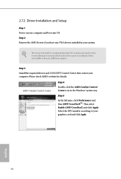
... AMD's website for AMD driver updates. Select the GPU number according to installation. The Catalyst Uninstaller is an optional download. Step 3 Install the required drivers and CATALYST Control Center then restart your system. Step 2 Remove the AMD drivers if you have any previously installed Catalyst drivers prior to your computer and boot into OS. We recommend using this utility to uninstall any VGA drivers installed in the Windows® system tray. AMD Catalyst Control...
... AMD's website for AMD driver updates. Select the GPU number according to installation. The Catalyst Uninstaller is an optional download. Step 3 Install the required drivers and CATALYST Control Center then restart your system. Step 2 Remove the AMD drivers if you have any previously installed Catalyst drivers prior to your computer and boot into OS. We recommend using this utility to uninstall any VGA drivers installed in the Windows® system tray. AMD Catalyst Control...
User Manual
Page 38
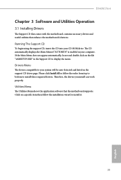
... support CD, insert the CD into your computer. B360M Pro4 Chapter 3 Software and Utilities Operation 3.1 Installing Drivers The Support CD that comes with the motherboard contains necessary drivers and useful utilities that the motherboard supports. If the Main Menu does not appear automatically, locate and double click on the file "ASRSETUP.EXE" in your CD-ROM drive. Please click Install All or follow the installation wizard to display the menu. Therefore, the drivers you install can work...
... support CD, insert the CD into your computer. B360M Pro4 Chapter 3 Software and Utilities Operation 3.1 Installing Drivers The Support CD that comes with the motherboard contains necessary drivers and useful utilities that the motherboard supports. If the Main Menu does not appear automatically, locate and double click on the file "ASRSETUP.EXE" in your CD-ROM drive. Please click Install All or follow the installation wizard to display the menu. Therefore, the drivers you install can work...
User Manual
Page 66
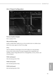
4.6.2 Chipset Configuration B360M Pro4 Primary Graphics Adapter Select a primary VGA. PCIE1 Link Speed Select the link speed for PCIE2. PCIE2 Link Speed Select the link speed for PCIE1. Above 4G Decoding Enable or disable 64bit capable Devices to be decoded in Above 4G Address Space (only if the system supports 64 bit PCI decoding). PCIE3 Link Speed Select the link speed for Directed I/O helps your virtual machine monitor better utilize hardware by...
4.6.2 Chipset Configuration B360M Pro4 Primary Graphics Adapter Select a primary VGA. PCIE1 Link Speed Select the link speed for PCIE2. PCIE2 Link Speed Select the link speed for PCIE1. Above 4G Decoding Enable or disable 64bit capable Devices to be decoded in Above 4G Address Space (only if the system supports 64 bit PCI decoding). PCIE3 Link Speed Select the link speed for Directed I/O helps your virtual machine monitor better utilize hardware by...

User Manual
Page 67
PCIE ASPM Support This option enables/disables the ASPM support for all PCH DMI devices. Set to Auto to the integrated graphics processor when the system boots up. DMI ASPM Support This option enables/disables the control of ASPM on CPU side of memory that is allocated to enable onboard HD audio and automatically disable it when a sound card is installed. Share Memory Configure the size of the DMI Link. Onboard HD Audio Enable/disable onboard HD audio. Front Panel Enable/disable front panel HD audio. Deep Sleep 62 English Onboard HDMI HD Audio Enable audio for...
PCIE ASPM Support This option enables/disables the ASPM support for all PCH DMI devices. Set to Auto to the integrated graphics processor when the system boots up. DMI ASPM Support This option enables/disables the control of ASPM on CPU side of memory that is allocated to enable onboard HD audio and automatically disable it when a sound card is installed. Share Memory Configure the size of the DMI Link. Onboard HD Audio Enable/disable onboard HD audio. Front Panel Enable/disable front panel HD audio. Deep Sleep 62 English Onboard HDMI HD Audio Enable audio for...
User Manual
Page 75
...), Auto ASRock Internet Flash downloads and updates the latest UEFI firmware version from our servers for you are having trouble with your PC. Please setup network configuration before using UEFI Tech Service. Internet Flash - 4.7 Tools UEFI Tech Service Contact ASRock Tech Service if you . Please setup network configuration before using Internet Flash. *For BIOS backup and recovery purpose, it is recommended to plug in your USB storage device and run Instant Flash to update your USB pen drive before using this function. 70 English Instant Flash Save UEFI files...
...), Auto ASRock Internet Flash downloads and updates the latest UEFI firmware version from our servers for you are having trouble with your PC. Please setup network configuration before using UEFI Tech Service. Internet Flash - 4.7 Tools UEFI Tech Service Contact ASRock Tech Service if you . Please setup network configuration before using Internet Flash. *For BIOS backup and recovery purpose, it is recommended to plug in your USB storage device and run Instant Flash to update your USB pen drive before using this function. 70 English Instant Flash Save UEFI files...

User Manual
Page 76
English 71 Network Configuration Use this to download the UEFI firmware. UEFI Download Server Select a server to configure internet connection settings for Internet Flash. B360M Pro4 Internet Setting Enable or disable sound effects in the setup utility.
English 71 Network Configuration Use this to download the UEFI firmware. UEFI Download Server Select a server to configure internet connection settings for Internet Flash. B360M Pro4 Internet Setting Enable or disable sound effects in the setup utility.

User Manual
Page 80
... Module. 75 English Intel(R) Platform Trust Technology Enable/disable Intel PTT in the UEFI Setup Utility. User Password Set or change the settings in ME. B360M Pro4 4.9 Security Screen In this section you may also clear the user password. Disable this item to remove the password. Leave it blank and press enter to change the supervisor/user password for Secure Boot. Secure Boot Use this option to change the password for the administrator account. You may set or change the settings in the UEFI Setup Utility.
... Module. 75 English Intel(R) Platform Trust Technology Enable/disable Intel PTT in the UEFI Setup Utility. User Password Set or change the settings in ME. B360M Pro4 4.9 Security Screen In this section you may also clear the user password. Disable this item to remove the password. Leave it blank and press enter to change the supervisor/user password for Secure Boot. Secure Boot Use this option to change the password for the administrator account. You may set or change the settings in the UEFI Setup Utility.

Quick Installation Guide
Page 4
...-pin DDR4 DIMM Slots (DDR4_A2, DDR4_B2) 5 CPU/Water Pump Fan Connector (CPU_FAN2/WP) 6 ATX Power Connector (ATXPWR1) 7 USB 3.1 Gen1 Header (USB3_5_6) 8 SATA3 Connector (SATA3_0) 9 SATA3 Connector (SATA3_1) 10 Chassis/Water Pump Fan Connector (CHA_FAN2/WP) 11 SATA3 Connector (SATA3_2) 12 SATA3 Connector (SATA3_3) 13 SATA3 Connector (SATA3_5) 14 SATA3 Connector (SATA3_4) 15 Clear CMOS Jumper (CLRMOS1) 16 Chassis Intrusion and Speaker Header (SPK_CI1) 17 System Panel Header (PANEL1) 18 USB 2.0 Header (USB3_4) 19 USB 2.0 Header (USB5) 20 TPM Header (TPMS1) 21 COM Port Header...
...-pin DDR4 DIMM Slots (DDR4_A2, DDR4_B2) 5 CPU/Water Pump Fan Connector (CPU_FAN2/WP) 6 ATX Power Connector (ATXPWR1) 7 USB 3.1 Gen1 Header (USB3_5_6) 8 SATA3 Connector (SATA3_0) 9 SATA3 Connector (SATA3_1) 10 Chassis/Water Pump Fan Connector (CHA_FAN2/WP) 11 SATA3 Connector (SATA3_2) 12 SATA3 Connector (SATA3_3) 13 SATA3 Connector (SATA3_5) 14 SATA3 Connector (SATA3_4) 15 Clear CMOS Jumper (CLRMOS1) 16 Chassis Intrusion and Speaker Header (SPK_CI1) 17 System Panel Header (PANEL1) 18 USB 2.0 Header (USB3_4) 19 USB 2.0 Header (USB5) 20 TPM Header (TPMS1) 21 COM Port Header...
Quick Installation Guide
Page 7
...to change without further notice. You may find the latest VGA cards and CPU support list on ASRock's website without notice. Because the motherboard specifications and the BIOS software might be subject to quality and endurance. ASRock website http://www.asrock.com. 1.1 Package Contents • ASRock B360M Pro4 Motherboard (Micro ATX Form Factor) • ASRock B360M Pro4 Quick Installation Guide • ASRock B360M Pro4 Support CD • 2 x Serial ATA (SATA) Data Cables (Optional) • 3 x Screws for purchasing ASRock B360M Pro4 motherboard, a reliable motherboard produced...
...to change without further notice. You may find the latest VGA cards and CPU support list on ASRock's website without notice. Because the motherboard specifications and the BIOS software might be subject to quality and endurance. ASRock website http://www.asrock.com. 1.1 Package Contents • ASRock B360M Pro4 Motherboard (Micro ATX Form Factor) • ASRock B360M Pro4 Quick Installation Guide • ASRock B360M Pro4 Support CD • 2 x Serial ATA (SATA) Data Cables (Optional) • 3 x Screws for purchasing ASRock B360M Pro4 motherboard, a reliable motherboard produced...
Quick Installation Guide
Page 11
...4-pin fan is in use. • 1 x 24 pin ATX Power Connector • 1 x 8 pin 12V Power Connector • 1 x Front Panel Audio Connector • 2 x USB 2.0 Headers (Support 3 USB 2.0 ports) (Supports ESD Protection) • 1 x USB 3.1 Gen1 Header (Supports 2 USB 3.1 Gen1 ports) (Supports ESD Protection) BIOS Feature • AMI UEFI Legal BIOS with multilingual GUI support • ACPI 6.0 Compliant wake up events • SMBIOS 2.7 Support • CPU, DRAM, PCH 1.0V, VCCIO, VCCSA, VCCST Voltage Multi-adjustment Hardware Monitor • Temperature Sensing: CPU, CPU/Water Pump, Chassis...
...4-pin fan is in use. • 1 x 24 pin ATX Power Connector • 1 x 8 pin 12V Power Connector • 1 x Front Panel Audio Connector • 2 x USB 2.0 Headers (Support 3 USB 2.0 ports) (Supports ESD Protection) • 1 x USB 3.1 Gen1 Header (Supports 2 USB 3.1 Gen1 ports) (Supports ESD Protection) BIOS Feature • AMI UEFI Legal BIOS with multilingual GUI support • ACPI 6.0 Compliant wake up events • SMBIOS 2.7 Support • CPU, DRAM, PCH 1.0V, VCCIO, VCCSA, VCCST Voltage Multi-adjustment Hardware Monitor • Temperature Sensing: CPU, CPU/Water Pump, Chassis...

Quick Installation Guide
Page 21
... chassis intrusion status. If you need to clear the CMOS when you just finish updating the BIOS, you must boot up the system first, and then shut it down before you update the BIOS. Please be noted that the password, date, time, and user default profile will be detected. If you to short the pins on the pins, the jumper is "Short". B360M Pro4 2.5 Jumpers Setup The illustration shows how jumpers...
... chassis intrusion status. If you need to clear the CMOS when you just finish updating the BIOS, you must boot up the system first, and then shut it down before you update the BIOS. Please be noted that the password, date, time, and user default profile will be detected. If you to short the pins on the pins, the jumper is "Short". B360M Pro4 2.5 Jumpers Setup The illustration shows how jumpers...


