

User Manual
Page 2
... implied warranties or conditions of this motherboard contains Perchlorate, a toxic substance controlled in the documentation or product. CALIFORNIA, USA ONLY he Lithium battery adopted on this documentation, ASRock does not provide warranty of ASRock Inc. Products and corporate names appearing...interference that may be constructed as a commitment by the California Legislature. In no responsibility for a particular purpose. ASRock assumes no event shall ASRock, its directors, oicers, employees, or agents be registered trademarks or copyrights of their respective companies, and are...
... implied warranties or conditions of this motherboard contains Perchlorate, a toxic substance controlled in the documentation or product. CALIFORNIA, USA ONLY he Lithium battery adopted on this documentation, ASRock does not provide warranty of ASRock Inc. Products and corporate names appearing...interference that may be constructed as a commitment by the California Legislature. In no responsibility for a particular purpose. ASRock assumes no event shall ASRock, its directors, oicers, employees, or agents be registered trademarks or copyrights of their respective companies, and are...

User Manual
Page 4
... 1 1.1 Package Contents 1 1.2 Speciications 2 1.3 Motherboard Layout 6 1.4 I/O Panel 8 Chapter 2 Installation 10 2.1 Installing the CPU 11 2.2 Installing the CPU Fan and Heatsink 14 2.3 Installing Memory Modules (DIMM) 15 2.4 Expansion Slots (PCI Express Slots) 17 2.5 Jumpers Setup 18 2.6 Onboard Headers and Connectors 19 Chapter 3 Software and Utilities Operation 23 3.1 Installing Drivers 23 3.2 ASRock Live Update & APP...
... 1 1.1 Package Contents 1 1.2 Speciications 2 1.3 Motherboard Layout 6 1.4 I/O Panel 8 Chapter 2 Installation 10 2.1 Installing the CPU 11 2.2 Installing the CPU Fan and Heatsink 14 2.3 Installing Memory Modules (DIMM) 15 2.4 Expansion Slots (PCI Express Slots) 17 2.5 Jumpers Setup 18 2.6 Onboard Headers and Connectors 19 Chapter 3 Software and Utilities Operation 23 3.1 Installing Drivers 23 3.2 ASRock Live Update & APP...
User Manual
Page 6
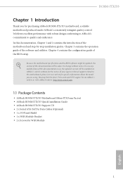
... change without further notice. ASRock website http://www.asrock.com. 1.1 Package Contents • ASRock B150M-ITX/D3 Motherboard (Mini-ITX Form Factor) • ASRock B150M-ITX/D3 Quick Installation Guide • ASRock B150M-ITX/D3 Support CD • 2 x Serial ATA (SATA) Data Cables (Optional) • 1 x I/O Panel Shield • 1 x WiFi Module Bracket • 2 x Screws for purchasing ASRock B150M-ITX/D3 motherboard, a reliable motherboard produced under ASRock's consistently stringent quality control...
... change without further notice. ASRock website http://www.asrock.com. 1.1 Package Contents • ASRock B150M-ITX/D3 Motherboard (Mini-ITX Form Factor) • ASRock B150M-ITX/D3 Quick Installation Guide • ASRock B150M-ITX/D3 Support CD • 2 x Serial ATA (SATA) Data Cables (Optional) • 1 x I/O Panel Shield • 1 x WiFi Module Bracket • 2 x Screws for purchasing ASRock B150M-ITX/D3 motherboard, a reliable motherboard produced under ASRock's consistently stringent quality control...
User Manual
Page 11
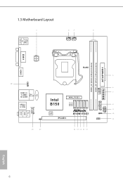
1.3 Motherboard Layout CHA_FAN1 CPU_FAN1 USB 2.0 T: USB1 B: USB2 PS2 Keyboard /Mouse DVI1 HDMI1 AT X P W R 1 DDR3_A1 (64 bit, 240-pin module) DDR3_B1 (64 bit, 240-pin module) ATX12V1 RoHS USB11 1 USB 3.0 T: USB3 B: USB4 Top: RJ-45 CMOS Battery USB 3.0 T: USB5 B: USB6 HD_AUDIO1 1 CI1 1 Intel B150 SATA3_4 SATA3_3 SATA3_2 SATA3_1 SATA3_0 MINI_PCIE1 128Mb BIOS PCIE1 B150M-ITX/D3 1 USB_9_10 1 SPEAKER1 1 1 PANEL1 CLRMOS1 1 Top: LINE IN Center: FRONT Bottom: MIC IN USB3_7_8 TPMS1 PLED PWRBTN HDLED RESET English 6
1.3 Motherboard Layout CHA_FAN1 CPU_FAN1 USB 2.0 T: USB1 B: USB2 PS2 Keyboard /Mouse DVI1 HDMI1 AT X P W R 1 DDR3_A1 (64 bit, 240-pin module) DDR3_B1 (64 bit, 240-pin module) ATX12V1 RoHS USB11 1 USB 3.0 T: USB3 B: USB4 Top: RJ-45 CMOS Battery USB 3.0 T: USB5 B: USB6 HD_AUDIO1 1 CI1 1 Intel B150 SATA3_4 SATA3_3 SATA3_2 SATA3_1 SATA3_0 MINI_PCIE1 128Mb BIOS PCIE1 B150M-ITX/D3 1 USB_9_10 1 SPEAKER1 1 1 PANEL1 CLRMOS1 1 Top: LINE IN Center: FRONT Bottom: MIC IN USB3_7_8 TPMS1 PLED PWRBTN HDLED RESET English 6

User Manual
Page 15
... wrist strap or touch a safety grounded object before installing or removing the motherboard components. Before you install the motherboard, study the coniguration of the following precautions before you install motherboard components or change any components, place them on a carpet. Doing so may...the components. • When placing screws to secure the motherboard to do not overtighten the screws! Chapter 2 Installation his is a Mini-ITX form factor motherboard. Pre-installation Precautions Take note of your motherboard directly on a grounded anti-static pad or in the bag...
... wrist strap or touch a safety grounded object before installing or removing the motherboard components. Before you install the motherboard, study the coniguration of the following precautions before you install motherboard components or change any components, place them on a carpet. Doing so may...the components. • When placing screws to secure the motherboard to do not overtighten the screws! Chapter 2 Installation his is a Mini-ITX form factor motherboard. Pre-installation Precautions Take note of your motherboard directly on a grounded anti-static pad or in the bag...

User Manual
Page 18
B150M-ITX/D3 Please save and replace the cover if the processor is removed. he cover must be placed if you wish to return the motherboard for ater service. 13 English
B150M-ITX/D3 Please save and replace the cover if the processor is removed. he cover must be placed if you wish to return the motherboard for ater service. 13 English

User Manual
Page 20
...at incorrect orientation. 15 English It is not allowed to activate Dual Channel Memory Technology with only one correct orientation. B150M-ITX/D3 2.3 Installing Memory Modules (DIMM) his motherboard provides two 240-pin DDR3/DDR3L (Double Data Rate 3) DIMM slots, and supports Dual Channel Memory Technology. 1.... otherwise, this motherboard and DIMM may be damaged. For dual channel coniguration, you always need to the motherboard and the DIMM if you force the DIMM into a DDR3/DDR3L slot; It will cause ...
...at incorrect orientation. 15 English It is not allowed to activate Dual Channel Memory Technology with only one correct orientation. B150M-ITX/D3 2.3 Installing Memory Modules (DIMM) his motherboard provides two 240-pin DDR3/DDR3L (Double Data Rate 3) DIMM slots, and supports Dual Channel Memory Technology. 1.... otherwise, this motherboard and DIMM may be damaged. For dual channel coniguration, you always need to the motherboard and the DIMM if you force the DIMM into a DDR3/DDR3L slot; It will cause ...

User Manual
Page 22
Before installing an expansion card, please make necessary hardware settings for WiFi and mSATA devices. 17 English Please read the documentation of the expansion card and make sure that the power supply is switched of or the power cord is 1 PCI Express slot and 1 mini-PCI Express slot on the motherboard. mini-PCIe slot: MPCIE1 (mini-PCIe slot) is used for the card before you start the installation. B150M-ITX/D3 2.4 Expansion Slots (PCI Express Slots) here is unplugged. PCIe slot: PCIE1 (PCIe 3.0 x16 slot) is used for PCI Express x16 lane width graphics cards.
Before installing an expansion card, please make necessary hardware settings for WiFi and mSATA devices. 17 English Please read the documentation of the expansion card and make sure that the power supply is switched of or the power cord is 1 PCI Express slot and 1 mini-PCI Express slot on the motherboard. mini-PCIe slot: MPCIE1 (mini-PCIe slot) is used for the card before you start the installation. B150M-ITX/D3 2.4 Expansion Slots (PCI Express Slots) here is unplugged. PCIe slot: PCIE1 (PCIe 3.0 x16 slot) is used for PCI Express x16 lane width graphics cards.

User Manual
Page 24
B150M-ITX/D3 2.6 Onboard Headers and Connectors Onboard headers and connectors are matched correctly. Placing jumper caps over these headers and connectors. he LED keeps blinking when ... LED is on when the system is in S4 sleep state or powered of your chassis front panel module to this header according to the motherboard. Do NOT place jumper caps over the headers and connectors will cause permanent damage to the pin assignments below. System Panel Header (9-pin PANEL1) (see...
B150M-ITX/D3 2.6 Onboard Headers and Connectors Onboard headers and connectors are matched correctly. Placing jumper caps over these headers and connectors. he LED keeps blinking when ... LED is on when the system is in S4 sleep state or powered of your chassis front panel module to this header according to the motherboard. Do NOT place jumper caps over the headers and connectors will cause permanent damage to the pin assignments below. System Panel Header (9-pin PANEL1) (see...

User Manual
Page 25
... 20 USB 3.0 Header (19-pin USB3_7_8) (see p.6, No. 19) 1 USB_PWR PP+ GND USB_PWR PP+ GND DUMMY here is one header and one header on this motherboard. Serial ATA3 Connectors (SATA3_0: see p.6, No. 12) (SATA3_1: see p.6, No. 13) (SATA3_2: see p.6, No. 14) (SATA3_3: see p.6, No. 15) (SATA3_4: see p.6, No. 18) OUT_RET MIC_RET... IntA_PA_SSRXIntA_PA_SSRX+ GND IntA_PA_SSTXIntA_PA_SSTX+ GND IntA_PA_DIntA_PA_D+ Vbus IntA_PB_SSRXIntA_PB_SSRX+ GND IntA_PB_SSTXIntA_PB_SSTX+ GND IntA_PB_DIntA_PB_D+ Dummy 1 Besides four USB 3.0 ports on the I/O panel, there is one port on this motherboard.
... 20 USB 3.0 Header (19-pin USB3_7_8) (see p.6, No. 19) 1 USB_PWR PP+ GND USB_PWR PP+ GND DUMMY here is one header and one header on this motherboard. Serial ATA3 Connectors (SATA3_0: see p.6, No. 12) (SATA3_1: see p.6, No. 13) (SATA3_2: see p.6, No. 14) (SATA3_3: see p.6, No. 15) (SATA3_4: see p.6, No. 18) OUT_RET MIC_RET... IntA_PA_SSRXIntA_PA_SSRX+ GND IntA_PA_SSTXIntA_PA_SSTX+ GND IntA_PA_DIntA_PA_D+ Vbus IntA_PB_SSRXIntA_PB_SSRX+ GND IntA_PB_SSTXIntA_PB_SSTX+ GND IntA_PB_DIntA_PB_D+ Dummy 1 Besides four USB 3.0 ports on the I/O panel, there is one port on this motherboard.
User Manual
Page 26
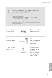
B150M-ITX/D3 1. Connect Mic_IN (MIC) to this header. Chassis Speaker Header (4-pin SPEAKER1) (see p.6, No. 10) DUMMY SPEAKER 1 +5V DUMMY Please connect the chassis speaker to MIC2_L. Chassis Fan Connector (4-pin CHA_FAN1) (see p.6, No. 3) 4 3 21 GND FAN_VOLTAGE CPU_FAN_SPEED FAN_SPEED_CONTROL his motherboard provides a 4-Pin CPU fan (Quiet Fan) connector. CPU Fan Connector (4-pin CPU_FAN1...
B150M-ITX/D3 1. Connect Mic_IN (MIC) to this header. Chassis Speaker Header (4-pin SPEAKER1) (see p.6, No. 10) DUMMY SPEAKER 1 +5V DUMMY Please connect the chassis speaker to MIC2_L. Chassis Fan Connector (4-pin CHA_FAN1) (see p.6, No. 3) 4 3 21 GND FAN_VOLTAGE CPU_FAN_SPEED FAN_SPEED_CONTROL his motherboard provides a 4-Pin CPU fan (Quiet Fan) connector. CPU Fan Connector (4-pin CPU_FAN1...

User Manual
Page 27
... platform integrity. 22 English ATX Power Connector (20-pin ATXPWR1) (see p.6, No. 8) his motherboard provides an 4-pin ATX 12V power connector. 1 GND Signal his motherboard supports CASE OPEN detection feature that detects if the chassis cove has been removed. Using a 24-...1) Chassis Intrusion Header (2-pin CI1) (see p.6, No. 17) TPM Header (17-pin TPMS1) (see p.6, No. 5) 10 12 1 11 his motherboard provides a 20-pin ATX power connector. his connector supports Trusted Platform Module (TPM) system, which can securely store keys, digital certiicates, passwords, and data...
... platform integrity. 22 English ATX Power Connector (20-pin ATXPWR1) (see p.6, No. 8) his motherboard provides an 4-pin ATX 12V power connector. 1 GND Signal his motherboard supports CASE OPEN detection feature that detects if the chassis cove has been removed. Using a 24-...1) Chassis Intrusion Header (2-pin CI1) (see p.6, No. 17) TPM Header (17-pin TPMS1) (see p.6, No. 5) 10 12 1 11 his motherboard provides a 20-pin ATX power connector. his connector supports Trusted Platform Module (TPM) system, which can securely store keys, digital certiicates, passwords, and data...
User Manual
Page 28
...compatibility, please download and install the following hot ix provided by Microsot. B150M-ITX/D3 Chapter 3 Software and Utilities Operation 3.1 Installing Drivers he Utilities Menu shows the application sotware that enhance the motherboard's features. If the Main Menu does not appear automatically, locate and ...the ile "ASRSETUP.EXE" in your computer. Utilities Menu he Support CD that comes with the motherboard contains necessary drivers and useful utilities that the motherboard supports. he drivers compatible to display the menu. Running The Support CD To begin using the support...
...compatibility, please download and install the following hot ix provided by Microsot. B150M-ITX/D3 Chapter 3 Software and Utilities Operation 3.1 Installing Drivers he Utilities Menu shows the application sotware that enhance the motherboard's features. If the Main Menu does not appear automatically, locate and ...the ile "ASRSETUP.EXE" in your computer. Utilities Menu he Support CD that comes with the motherboard contains necessary drivers and useful utilities that the motherboard supports. he drivers compatible to display the menu. Running The Support CD To begin using the support...

User Manual
Page 29
... website of the selected news and know more . Click on your desktop to access ASRock Live Update & APP Shop *You need to be connected to the Internet to download apps from the ASRock Live Update & APP Shop. 3.2.1 UI Overview Category Panel Hot News Information Panel Category... optimize your system and keep your ASRock computer. Information Panel: he hot news section displays the various latest news. 3.2 ASRock Live Update & APP Shop he ASRock Live Update & APP Shop is an online store for purchasing and downloading sotware applications for your motherboard up to date simply with a few...
... website of the selected news and know more . Click on your desktop to access ASRock Live Update & APP Shop *You need to be connected to the Internet to download apps from the ASRock Live Update & APP Shop. 3.2.1 UI Overview Category Panel Hot News Information Panel Category... optimize your system and keep your ASRock computer. Information Panel: he hot news section displays the various latest news. 3.2 ASRock Live Update & APP Shop he ASRock Live Update & APP Shop is an online store for purchasing and downloading sotware applications for your motherboard up to date simply with a few...

User Manual
Page 35
...A Windows® 7 installation disk or USB drive • USB 3.0 drivers (included in the ASRock Support CD or website) • A Windows® PC • Win7 USB Patcher (included in the ASRock Support CD or website) Scenarios You have an ODD and PS/2 ports: If there is an ...7 installation disk with the "Win7 USB Patcher". 3.3 Enabling USB Ports for Windows® 7 Installation Intel® Braswell and Skylake has removed their motherboard won't work. USB3.0). Please set PS/S Simulator back to install Windows® 7 OS. 30 English In order for the Enhanced Host Controller Interface...
...A Windows® 7 installation disk or USB drive • USB 3.0 drivers (included in the ASRock Support CD or website) • A Windows® PC • Win7 USB Patcher (included in the ASRock Support CD or website) Scenarios You have an ODD and PS/2 ports: If there is an ...7 installation disk with the "Win7 USB Patcher". 3.3 Enabling USB Ports for Windows® 7 Installation Intel® Braswell and Skylake has removed their motherboard won't work. USB3.0). Please set PS/S Simulator back to install Windows® 7 OS. 30 English In order for the Enhanced Host Controller Interface...

User Manual
Page 43
... sending a column address to CAS# Delay : he delay between the opening the next row. DRAM Frequency OC Preset If the DRAM frequency is selected, the motherboard will be issued. DRAM Timing Coniguration Load XMP Setting Load XMP settings to conirm and apply your new settings. DRAM Tweaker Fine tune the DRAM...
... sending a column address to CAS# Delay : he delay between the opening the next row. DRAM Frequency OC Preset If the DRAM frequency is selected, the motherboard will be issued. DRAM Timing Coniguration Load XMP Setting Load XMP settings to conirm and apply your new settings. DRAM Tweaker Fine tune the DRAM...

User Manual
Page 64
...choose Customize to monitor the status of the hardware on your system, including the parameters of the CPU temperature, motherboard temperature, fan speed and voltage. B150M-ITX/D3 4.6 Hardware Health Event Monitoring Screen his section allows you to set 5 CPU temperatures and assign a ... fan temperature source for each temperature. Over Temperature Protection When Over Temperature Protection is enabled, the system automatically shuts down when the motherboard is overheated. 59 English Fan-Tastic Tuning Select a fan mode for CPU Fans 1&2, or choose Customize to set 5 CPU temperatures...
...choose Customize to monitor the status of the hardware on your system, including the parameters of the CPU temperature, motherboard temperature, fan speed and voltage. B150M-ITX/D3 4.6 Hardware Health Event Monitoring Screen his section allows you to set 5 CPU temperatures and assign a ... fan temperature source for each temperature. Over Temperature Protection When Over Temperature Protection is enabled, the system automatically shuts down when the motherboard is overheated. 59 English Fan-Tastic Tuning Select a fan mode for CPU Fans 1&2, or choose Customize to set 5 CPU temperatures...

