User Manual
Page 4
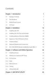
...1 1.2 Specifications 2 1.3 Motherboard Layout 5 1.4 I/O Panel 9 Chapter 2 Installation 12 2.1 Installing the CPU 13 2.2 Installing the CPU Fan and Heatsink 15 2.3 Installing Memory Modules (DIMM) 24 2.4 Expansion Slots (PCI Express Slots) 26 2.5 Jumpers Setup 27 2.6 Onboard Headers and Connectors 28 2.7 M.2_SSD (NGFF) Module Installation Guide (M2_1) 33 Chapter 3 Software and Utilities Operation 36 3.1 Installing Drivers 36 3.2 ASRock Live Update & APP Shop 37 3.2.1 UI Overview 37 3.2.2 Apps 38 3.2.3 BIOS & Drivers 41 3.2.4 Setting 42 3.3 ASRock RGB LED 43...
...1 1.2 Specifications 2 1.3 Motherboard Layout 5 1.4 I/O Panel 9 Chapter 2 Installation 12 2.1 Installing the CPU 13 2.2 Installing the CPU Fan and Heatsink 15 2.3 Installing Memory Modules (DIMM) 24 2.4 Expansion Slots (PCI Express Slots) 26 2.5 Jumpers Setup 27 2.6 Onboard Headers and Connectors 28 2.7 M.2_SSD (NGFF) Module Installation Guide (M2_1) 33 Chapter 3 Software and Utilities Operation 36 3.1 Installing Drivers 36 3.2 ASRock Live Update & APP Shop 37 3.2.1 UI Overview 37 3.2.2 Apps 38 3.2.3 BIOS & Drivers 41 3.2.4 Setting 42 3.3 ASRock RGB LED 43...
User Manual
Page 6
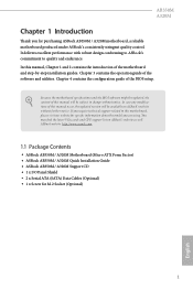
... Installation Guide • ASRock AB350M / A320M Support CD • 1 x I/O Panel Shield • 2 x Serial ATA (SATA) Data Cables (Optional) • 1 x Screw for purchasing ASRock AB350M / A320M motherboard, a reliable motherboard produced under ASRock's consistently stringent quality control. AB350M A320M Chapter 1 Introduction Thank you are using. In this manual will be subject to change without further notice. Because the motherboard specifications and the BIOS software might be updated, the content of the BIOS setup. Chapter 4 contains the configuration guide of this manual...
... Installation Guide • ASRock AB350M / A320M Support CD • 1 x I/O Panel Shield • 2 x Serial ATA (SATA) Data Cables (Optional) • 1 x Screw for purchasing ASRock AB350M / A320M motherboard, a reliable motherboard produced under ASRock's consistently stringent quality control. AB350M A320M Chapter 1 Introduction Thank you are using. In this manual will be subject to change without further notice. Because the motherboard specifications and the BIOS software might be updated, the content of the BIOS setup. Chapter 4 contains the configuration guide of this manual...
User Manual
Page 7
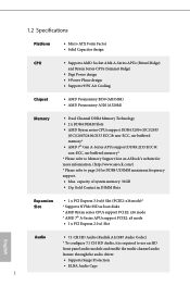
....asrock.com/) * Please refer to use an HD front panel audio module and enable the multi-channel audio feature through the audio driver. • Supports Surge Protection • ELNA Audio Caps 2 capacity of system memory: 32GB • 15μ Gold Contact in DIMM Slots Expansion Slot • 1 x PCI Express 3.0 x16 Slot (PCIE2: x16 mode)* * Supports NVMe SSD as boot disks * AMD Ryzen series CPUs support PCIE2: x16 mode * AMD 7th A-Series APUs support PCIE2: x8 mode • 1 x PCI Express 2.0 x1 Slot English Audio...
....asrock.com/) * Please refer to use an HD front panel audio module and enable the multi-channel audio feature through the audio driver. • Supports Surge Protection • ELNA Audio Caps 2 capacity of system memory: 32GB • 15μ Gold Contact in DIMM Slots Expansion Slot • 1 x PCI Express 3.0 x16 Slot (PCIE2: x16 mode)* * Supports NVMe SSD as boot disks * AMD Ryzen series CPUs support PCIE2: x16 mode * AMD 7th A-Series APUs support PCIE2: x8 mode • 1 x PCI Express 2.0 x1 Slot English Audio...

User Manual
Page 8
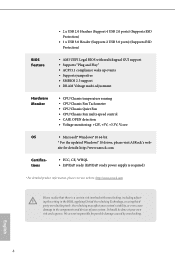
... SPEED LED) • HD Audio Jacks: Line in / Front Speaker / Microphone Storage • 4 x SATA3 6.0 Gb/s Connectors, support RAID (RAID 0, RAID 1 and RAID 10), NCQ, AHCI and Hot Plug* • 1 x Ultra M.2 Socket (M2_1), supports type 2242/2260/2280 M.2 SATA3 6.0 Gb/s module and M.2 PCI Express module up to Gen3 x4 (32 Gb/s) (with Ryzen Series CPU) or Gen3 x2 (16 Gb/s) (with A-Series APU)** ** Supports NVMe SSD as boot disks ** Supports ASRock U.2 Kit Connector • 1 x COM Port Header • 1 x TPM Header • 1 x Chassis...
... SPEED LED) • HD Audio Jacks: Line in / Front Speaker / Microphone Storage • 4 x SATA3 6.0 Gb/s Connectors, support RAID (RAID 0, RAID 1 and RAID 10), NCQ, AHCI and Hot Plug* • 1 x Ultra M.2 Socket (M2_1), supports type 2242/2260/2280 M.2 SATA3 6.0 Gb/s module and M.2 PCI Express module up to Gen3 x4 (32 Gb/s) (with Ryzen Series CPU) or Gen3 x2 (16 Gb/s) (with A-Series APU)** ** Supports NVMe SSD as boot disks ** Supports ASRock U.2 Kit Connector • 1 x COM Port Header • 1 x TPM Header • 1 x Chassis...
User Manual
Page 9
...; CPU/Chassis Quiet Fan • CPU/Chassis Fan multi-speed control • CASE OPEN detection • Voltage monitoring: +12V, +5V, +3.3V, Vcore OS • Microsoft® Windows® 10 64-bit * For the updated Windows® 10 driver, please visit ASRock's web- • 2 x USB 2.0 Headers (Support 4 USB 2.0 ports) (Supports ESD Protection) • 1 x USB 3.0 Header (Supports 2 USB 3.0 ports) (Supports ESD Protection) BIOS Feature • AMI UEFI Legal BIOS with overclocking, including adjusting the setting in the BIOS, applying Untied Overclocking Technology, or using thirdparty...
...; CPU/Chassis Quiet Fan • CPU/Chassis Fan multi-speed control • CASE OPEN detection • Voltage monitoring: +12V, +5V, +3.3V, Vcore OS • Microsoft® Windows® 10 64-bit * For the updated Windows® 10 driver, please visit ASRock's web- • 2 x USB 2.0 Headers (Support 4 USB 2.0 ports) (Supports ESD Protection) • 1 x USB 3.0 Header (Supports 2 USB 3.0 ports) (Supports ESD Protection) BIOS Feature • AMI UEFI Legal BIOS with overclocking, including adjusting the setting in the BIOS, applying Untied Overclocking Technology, or using thirdparty...

User Manual
Page 11
...-pin DDR4 DIMM Slots (DDR4_A1, DDR4_B1) 3 CPU Fan Connector (CPU_FAN1) 4 ATX Power Connector (ATXPWR1) 5 USB 3.0 Header (USB3_7_8) 6 USB 2.0 Header (USB_5_6) 7 USB 2.0 Header (USB_3_4) 8 SATA3 Connector (SATA3_3) 9 SATA3 Connector (SATA3_4) 10 SATA3 Connector (SATA3_2) 11 SATA3 Connector (SATA3_1) 12 System Panel Header (PANEL1) 13 Chassis Intrusion and Speaker Header (SPK_CI1) 14 Chassis Fan Connector (CHA_FAN2) 15 COM Port Header (COM1) 16 TPM Header (TPMS1) 17 RGB LED Header (RGB_LED1) 18 Clear CMOS Jumper (CLRCMOS1) 19 Chassis Fan Connector (CHA_FAN1) 20 Front Panel Audio Header (HD_AUDIO1...
...-pin DDR4 DIMM Slots (DDR4_A1, DDR4_B1) 3 CPU Fan Connector (CPU_FAN1) 4 ATX Power Connector (ATXPWR1) 5 USB 3.0 Header (USB3_7_8) 6 USB 2.0 Header (USB_5_6) 7 USB 2.0 Header (USB_3_4) 8 SATA3 Connector (SATA3_3) 9 SATA3 Connector (SATA3_4) 10 SATA3 Connector (SATA3_2) 11 SATA3 Connector (SATA3_1) 12 System Panel Header (PANEL1) 13 Chassis Intrusion and Speaker Header (SPK_CI1) 14 Chassis Fan Connector (CHA_FAN2) 15 COM Port Header (COM1) 16 TPM Header (TPMS1) 17 RGB LED Header (RGB_LED1) 18 Clear CMOS Jumper (CLRCMOS1) 19 Chassis Fan Connector (CHA_FAN1) 20 Front Panel Audio Header (HD_AUDIO1...

User Manual
Page 13
...-pin DDR4 DIMM Slots (DDR4_A1, DDR4_B1) 3 CPU Fan Connector (CPU_FAN1) 4 ATX Power Connector (ATXPWR1) 5 USB 3.0 Header (USB3_7_8) 6 USB 2.0 Header (USB_5_6) 7 USB 2.0 Header (USB_3_4) 8 SATA3 Connector (SATA3_3) 9 SATA3 Connector (SATA3_4) 10 SATA3 Connector (SATA3_2) 11 SATA3 Connector (SATA3_1) 12 System Panel Header (PANEL1) 13 Chassis Intrusion and Speaker Header (SPK_CI1) 14 Chassis Fan Connector (CHA_FAN2) 15 COM Port Header (COM1) 16 TPM Header (TPMS1) 17 RGB LED Header (RGB_LED1) 18 Clear CMOS Jumper (CLRCMOS1) 19 Chassis Fan Connector (CHA_FAN1) 20 Front Panel Audio Header (HD_AUDIO1...
...-pin DDR4 DIMM Slots (DDR4_A1, DDR4_B1) 3 CPU Fan Connector (CPU_FAN1) 4 ATX Power Connector (ATXPWR1) 5 USB 3.0 Header (USB3_7_8) 6 USB 2.0 Header (USB_5_6) 7 USB 2.0 Header (USB_3_4) 8 SATA3 Connector (SATA3_3) 9 SATA3 Connector (SATA3_4) 10 SATA3 Connector (SATA3_2) 11 SATA3 Connector (SATA3_1) 12 System Panel Header (PANEL1) 13 Chassis Intrusion and Speaker Header (SPK_CI1) 14 Chassis Fan Connector (CHA_FAN2) 15 COM Port Header (COM1) 16 TPM Header (TPMS1) 17 RGB LED Header (RGB_LED1) 18 Clear CMOS Jumper (CLRCMOS1) 19 Chassis Fan Connector (CHA_FAN1) 20 Front Panel Audio Header (HD_AUDIO1...

User Manual
Page 32
... not clear the CMOS right after you update the BIOS. Please adjust the BIOS option "Clear Status" to default setup, please turn off the computer and unplug the power cord from the power supply. When the jumper cap is "Short". To clear and reset the system parameters to clear the record of previous chassis intrusion status. The illustration shows a 3-pin jumper whose pin1 and pin2 are setup. Please be noted that the password...
... not clear the CMOS right after you update the BIOS. Please adjust the BIOS option "Clear Status" to default setup, please turn off the computer and unplug the power cord from the power supply. When the jumper cap is "Short". To clear and reset the system parameters to clear the record of previous chassis intrusion status. The illustration shows a 3-pin jumper whose pin1 and pin2 are setup. Please be noted that the password...
User Manual
Page 41
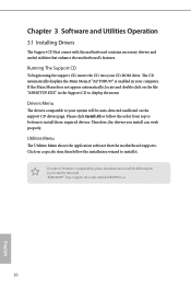
... into your system will be auto-detected and listed on a specific item then follow the order from top to bottom to display the menu. Chapter 3 Software and Utilities Operation 3.1 Installing Drivers The Support CD that comes with the motherboard contains necessary drivers and useful utilities that the motherboard supports. Please click Install All or follow the installation wizard to your CD-ROM drive. "KB2720599": http://support.microsoft.com/kb/2720599/en...
... into your system will be auto-detected and listed on a specific item then follow the order from top to bottom to display the menu. Chapter 3 Software and Utilities Operation 3.1 Installing Drivers The Support CD that comes with the motherboard contains necessary drivers and useful utilities that the motherboard supports. Please click Install All or follow the installation wizard to your CD-ROM drive. "KB2720599": http://support.microsoft.com/kb/2720599/en...

User Manual
Page 55
... reduce CPU voltage and memory frequency, and lead to system stability or compatibility issue with some memory modules or power supplies. Please set to [Enabled], a VMM (Virtual Machine Architecture) can utilize the additional hardware capabilities provided by AMD-V. The default value is [Enabled]. 50 English Configuration options: [Enabled] and [Disabled]. 4.4.1 CPU Configuration Cool 'n' Quiet Use this item to [Disable] if above issue occurs. C6 Mode Use this to enable or disable AMD CPU fTPM. AMD fTPM Switch Use this item to enable or disable AMD...
... reduce CPU voltage and memory frequency, and lead to system stability or compatibility issue with some memory modules or power supplies. Please set to [Enabled], a VMM (Virtual Machine Architecture) can utilize the additional hardware capabilities provided by AMD-V. The default value is [Enabled]. 50 English Configuration options: [Enabled] and [Disabled]. 4.4.1 CPU Configuration Cool 'n' Quiet Use this item to [Disable] if above issue occurs. C6 Mode Use this to enable or disable AMD CPU fTPM. AMD fTPM Switch Use this item to enable or disable AMD...
User Manual
Page 63
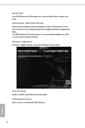
...Internet Flash - DHCP (Auto IP), Auto ASRock Internet Flash downloads and updates the latest UEFI firmware version from our servers for Internet Flash. Instant Flash Save UEFI files in your USB storage device and run Instant Flash to update your USB pen drive before using Internet Flash. *For BIOS backup and recovery purpose, it is recommended to download the UEFI firmware. 58 English Please setup network configuration before using this to configure internet connection settings for you. UEFI Download Server Select a server to plug in the setup utility. Network Configuration Use...
...Internet Flash - DHCP (Auto IP), Auto ASRock Internet Flash downloads and updates the latest UEFI firmware version from our servers for Internet Flash. Instant Flash Save UEFI files in your USB storage device and run Instant Flash to update your USB pen drive before using Internet Flash. *For BIOS backup and recovery purpose, it is recommended to download the UEFI firmware. 58 English Please setup network configuration before using this to configure internet connection settings for you. UEFI Download Server Select a server to plug in the setup utility. Network Configuration Use...

Quick Installation Guide
Page 4
...-pin DDR4 DIMM Slots (DDR4_A1, DDR4_B1) 3 CPU Fan Connector (CPU_FAN1) 4 ATX Power Connector (ATXPWR1) 5 USB 3.0 Header (USB3_7_8) 6 USB 2.0 Header (USB_5_6) 7 USB 2.0 Header (USB_3_4) 8 SATA3 Connector (SATA3_3) 9 SATA3 Connector (SATA3_4) 10 SATA3 Connector (SATA3_2) 11 SATA3 Connector (SATA3_1) 12 System Panel Header (PANEL1) 13 Chassis Intrusion and Speaker Header (SPK_CI1) 14 Chassis Fan Connector (CHA_FAN2) 15 COM Port Header (COM1) 16 TPM Header (TPMS1) 17 RGB LED Header (RGB_LED1) 18 Clear CMOS Jumper (CLRCMOS1) 19 Chassis Fan Connector (CHA_FAN1) 20 Front Panel Audio Header (HD_AUDIO1...
...-pin DDR4 DIMM Slots (DDR4_A1, DDR4_B1) 3 CPU Fan Connector (CPU_FAN1) 4 ATX Power Connector (ATXPWR1) 5 USB 3.0 Header (USB3_7_8) 6 USB 2.0 Header (USB_5_6) 7 USB 2.0 Header (USB_3_4) 8 SATA3 Connector (SATA3_3) 9 SATA3 Connector (SATA3_4) 10 SATA3 Connector (SATA3_2) 11 SATA3 Connector (SATA3_1) 12 System Panel Header (PANEL1) 13 Chassis Intrusion and Speaker Header (SPK_CI1) 14 Chassis Fan Connector (CHA_FAN2) 15 COM Port Header (COM1) 16 TPM Header (TPMS1) 17 RGB LED Header (RGB_LED1) 18 Clear CMOS Jumper (CLRCMOS1) 19 Chassis Fan Connector (CHA_FAN1) 20 Front Panel Audio Header (HD_AUDIO1...

Quick Installation Guide
Page 6
...-pin DDR4 DIMM Slots (DDR4_A1, DDR4_B1) 3 CPU Fan Connector (CPU_FAN1) 4 ATX Power Connector (ATXPWR1) 5 USB 3.0 Header (USB3_7_8) 6 USB 2.0 Header (USB_5_6) 7 USB 2.0 Header (USB_3_4) 8 SATA3 Connector (SATA3_3) 9 SATA3 Connector (SATA3_4) 10 SATA3 Connector (SATA3_2) 11 SATA3 Connector (SATA3_1) 12 System Panel Header (PANEL1) 13 Chassis Intrusion and Speaker Header (SPK_CI1) 14 Chassis Fan Connector (CHA_FAN2) 15 COM Port Header (COM1) 16 TPM Header (TPMS1) 17 RGB LED Header (RGB_LED1) 18 Clear CMOS Jumper (CLRCMOS1) 19 Chassis Fan Connector (CHA_FAN1) 20 Front Panel Audio Header (HD_AUDIO1...
...-pin DDR4 DIMM Slots (DDR4_A1, DDR4_B1) 3 CPU Fan Connector (CPU_FAN1) 4 ATX Power Connector (ATXPWR1) 5 USB 3.0 Header (USB3_7_8) 6 USB 2.0 Header (USB_5_6) 7 USB 2.0 Header (USB_3_4) 8 SATA3 Connector (SATA3_3) 9 SATA3 Connector (SATA3_4) 10 SATA3 Connector (SATA3_2) 11 SATA3 Connector (SATA3_1) 12 System Panel Header (PANEL1) 13 Chassis Intrusion and Speaker Header (SPK_CI1) 14 Chassis Fan Connector (CHA_FAN2) 15 COM Port Header (COM1) 16 TPM Header (TPMS1) 17 RGB LED Header (RGB_LED1) 18 Clear CMOS Jumper (CLRCMOS1) 19 Chassis Fan Connector (CHA_FAN1) 20 Front Panel Audio Header (HD_AUDIO1...

Quick Installation Guide
Page 12
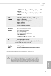
... SPEED LED) • HD Audio Jacks: Line in / Front Speaker / Microphone Storage • 4 x SATA3 6.0 Gb/s Connectors, support RAID (RAID 0, RAID 1 and RAID 10), NCQ, AHCI and Hot Plug* • 1 x Ultra M.2 Socket (M2_1), supports type 2242/2260/2280 M.2 SATA3 6.0 Gb/s module and M.2 PCI Express module up to Gen3 x4 (32 Gb/s) (with Ryzen Series CPU) or Gen3 x2 (16 Gb/s) (with A-Series APU)** ** Supports NVMe SSD as boot disks ** Supports ASRock U.2 Kit Connector • 1 x COM Port Header • 1 x TPM Header • 1 x Chassis...
... SPEED LED) • HD Audio Jacks: Line in / Front Speaker / Microphone Storage • 4 x SATA3 6.0 Gb/s Connectors, support RAID (RAID 0, RAID 1 and RAID 10), NCQ, AHCI and Hot Plug* • 1 x Ultra M.2 Socket (M2_1), supports type 2242/2260/2280 M.2 SATA3 6.0 Gb/s module and M.2 PCI Express module up to Gen3 x4 (32 Gb/s) (with Ryzen Series CPU) or Gen3 x2 (16 Gb/s) (with A-Series APU)** ** Supports NVMe SSD as boot disks ** Supports ASRock U.2 Kit Connector • 1 x COM Port Header • 1 x TPM Header • 1 x Chassis...
Quick Installation Guide
Page 13
... Fan • CPU/Chassis Fan multi-speed control • CASE OPEN detection • Voltage monitoring: +12V, +5V, +3.3V, Vcore OS • Microsoft® Windows® 10 64-bit * For the updated Windows® 10 driver, please visit ASRock's web- English 11 AB350M A320M • 2 x USB 2.0 Headers (Support 4 USB 2.0 ports) (Supports ESD Protection) • 1 x USB 3.0 Header (Supports 2 USB 3.0 ports) (Supports ESD Protection) BIOS Feature • AMI UEFI Legal BIOS with overclocking, including adjusting the setting in the BIOS, applying Untied Overclocking Technology, or using...
... Fan • CPU/Chassis Fan multi-speed control • CASE OPEN detection • Voltage monitoring: +12V, +5V, +3.3V, Vcore OS • Microsoft® Windows® 10 64-bit * For the updated Windows® 10 driver, please visit ASRock's web- English 11 AB350M A320M • 2 x USB 2.0 Headers (Support 4 USB 2.0 ports) (Supports ESD Protection) • 1 x USB 3.0 Header (Supports 2 USB 3.0 ports) (Supports ESD Protection) BIOS Feature • AMI UEFI Legal BIOS with overclocking, including adjusting the setting in the BIOS, applying Untied Overclocking Technology, or using...

Quick Installation Guide
Page 29
..., use a jumper cap to default setup, please turn off the computer and unplug the power cord from the power supply. However, please do the clear-CMOS action. When the jumper cap is placed on the pins, the jumper is "Open". After waiting for 5 seconds. Please be noted that the password, date, time, and user default profile will be detected. Please adjust the BIOS option "Clear Status" to clear the CMOS when...
..., use a jumper cap to default setup, please turn off the computer and unplug the power cord from the power supply. However, please do the clear-CMOS action. When the jumper cap is placed on the pins, the jumper is "Open". After waiting for 5 seconds. Please be noted that the password, date, time, and user default profile will be detected. Please adjust the BIOS option "Clear Status" to clear the CMOS when...
RAID Installation Guide
Page 2
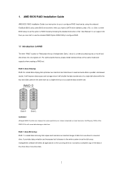
...) RAID 1 is an instruction for "Redundant Array of the data in the other drive if one logical unit. AMD BIOS RAID Installation Guide AMD BIOS RAID Installation Guide is called data striping that copies and maintains an identical image of the same model and capacity when creating a RAID set the option to RAID mode by using the onboard FastBuild BIOS utility under BIOS environment. It will improve data access and storage since the disk array management software will...
...) RAID 1 is an instruction for "Redundant Array of the data in the other drive if one logical unit. AMD BIOS RAID Installation Guide AMD BIOS RAID Installation Guide is called data striping that copies and maintains an identical image of the same model and capacity when creating a RAID set the option to RAID mode by using the onboard FastBuild BIOS utility under BIOS environment. It will improve data access and storage since the disk array management software will...

RAID Installation Guide
Page 5
...; 8 64-bit / 8.1 64-bit / 10 64-bit only) 5 B. Set the "SATA Mode" option to finish the driver copy process. STEP 2: Create and configure the RAID disk A. Follow the instruction inside your Windows version (Windows 7/8/8.1). B. D. Click to save to enter UEFI setup utility. Please install the DVD-ROM into one of the USB port. During system boot, press or key to exit. D. After RAID driver is under /AMD64 directly. D. During system boot, press to Tools Easy RAID Installer F. Go to enter legacy RAID ROM utility. B. 1.3 Installing Windows®...
...; 8 64-bit / 8.1 64-bit / 10 64-bit only) 5 B. Set the "SATA Mode" option to finish the driver copy process. STEP 2: Create and configure the RAID disk A. Follow the instruction inside your Windows version (Windows 7/8/8.1). B. D. Click to save to enter UEFI setup utility. Please install the DVD-ROM into one of the USB port. During system boot, press or key to exit. D. After RAID driver is under /AMD64 directly. D. During system boot, press to Tools Easy RAID Installer F. Go to enter legacy RAID ROM utility. B. 1.3 Installing Windows®...

RAID Installation Guide
Page 9
... driver is loaded, the RAID disk will be created in MBR mode which support IDE Combined Mode. *Due to the AMD A68H chipset limitation, please install the DVD-ROM into one of the SATA ports 5 ~ 8 which the size of the SATA ports 1 ~ 4 and set the "SATA Mode" option back to in BIOS setup. Go to enter UEFI setup utility. During system boot, press or key to Advanced Storage Configuration. Follow instructions to enter UEFI setup utility. Click to find the driver inside the RAID ROM utility to create the target RAID disk...
... driver is loaded, the RAID disk will be created in MBR mode which support IDE Combined Mode. *Due to the AMD A68H chipset limitation, please install the DVD-ROM into one of the SATA ports 5 ~ 8 which the size of the SATA ports 1 ~ 4 and set the "SATA Mode" option back to in BIOS setup. Go to enter UEFI setup utility. During system boot, press or key to Advanced Storage Configuration. Follow instructions to enter UEFI setup utility. Click to find the driver inside the RAID ROM utility to create the target RAID disk...
RAID Installation Guide
Page 18
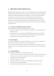
AMD Windows RAID Installation Guide AMD Windows RAID Installation Guide is installed. If you to configure RAID functions by using RAIDXpert RAID management software under the same directory where RAIDXpert is an instruction for you do not have one of all major events/alarms, memory cache management, drive event logging, logical drive maintenance, rebuild, and access to install RAIDXpert on your Windows-based PC or Server. 1. Follow the prompts in the RAID configuration (server, controller, logical drives, physical...
AMD Windows RAID Installation Guide AMD Windows RAID Installation Guide is installed. If you to configure RAID functions by using RAIDXpert RAID management software under the same directory where RAIDXpert is an instruction for you do not have one of all major events/alarms, memory cache management, drive event logging, logical drive maintenance, rebuild, and access to install RAIDXpert on your Windows-based PC or Server. 1. Follow the prompts in the RAID configuration (server, controller, logical drives, physical...


