
User Manual
Page 4
...1 1.2 Specifications 2 1.3 Motherboard Layout 5 1.4 I/O Panel 9 Chapter 2 Installation 12 2.1 Installing the CPU 13 2.2 Installing the CPU Fan and Heatsink 15 2.3 Installing Memory Modules (DIMM) 24 2.4 Expansion Slots (PCI Express Slots) 26 2.5 Jumpers Setup 27 2.6 Onboard Headers and Connectors 28 2.7 M.2_SSD (NGFF) Module Installation Guide (M2_1) 33 Chapter 3 Software and Utilities Operation 36 3.1 Installing Drivers 36 3.2 ASRock Live Update & APP Shop 37 3.2.1 UI Overview 37 3.2.2 Apps 38 3.2.3 BIOS & Drivers 41 3.2.4 Setting 42 3.3 ASRock RGB LED 43...
...1 1.2 Specifications 2 1.3 Motherboard Layout 5 1.4 I/O Panel 9 Chapter 2 Installation 12 2.1 Installing the CPU 13 2.2 Installing the CPU Fan and Heatsink 15 2.3 Installing Memory Modules (DIMM) 24 2.4 Expansion Slots (PCI Express Slots) 26 2.5 Jumpers Setup 27 2.6 Onboard Headers and Connectors 28 2.7 M.2_SSD (NGFF) Module Installation Guide (M2_1) 33 Chapter 3 Software and Utilities Operation 36 3.1 Installing Drivers 36 3.2 ASRock Live Update & APP Shop 37 3.2.1 UI Overview 37 3.2.2 Apps 38 3.2.3 BIOS & Drivers 41 3.2.4 Setting 42 3.3 ASRock RGB LED 43...
User Manual
Page 6
...8226; ASRock AB350M / A320M Quick Installation Guide • ASRock AB350M / A320M Support CD • 1 x I/O Panel Shield • 2 x Serial ATA (SATA) Data Cables (Optional) • 1 x Screw for purchasing ASRock AB350M / A320M motherboard, a reliable motherboard produced under ASRock's consistently stringent quality control. It delivers excellent performance with robust design conforming to ASRock's commitment to change without further notice. Chapter 3 contains the operation guide of the BIOS setup. Because the motherboard specifications and the BIOS software might be updated, the...
...8226; ASRock AB350M / A320M Quick Installation Guide • ASRock AB350M / A320M Support CD • 1 x I/O Panel Shield • 2 x Serial ATA (SATA) Data Cables (Optional) • 1 x Screw for purchasing ASRock AB350M / A320M motherboard, a reliable motherboard produced under ASRock's consistently stringent quality control. It delivers excellent performance with robust design conforming to ASRock's commitment to change without further notice. Chapter 3 contains the operation guide of the BIOS setup. Because the motherboard specifications and the BIOS software might be updated, the...
User Manual
Page 7
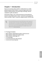
... refer to Memory Support List on ASRock's website for DDR4 UDIMM maximum frequency support. • Max. capacity of system memory: 32GB • 15μ Gold Contact in DIMM Slots Expansion Slot • 1 x PCI Express 3.0 x16 Slot (PCIE2: x16 mode)* * Supports NVMe SSD as boot disks * AMD Ryzen series CPUs support PCIE2: x16 mode * AMD 7th A-Series APUs support PCIE2: x8 mode • 1 x PCI Express 2.0 x1 Slot English Audio • 7.1 CH HD Audio (Realtek ALC887 Audio Codec) * To configure 7.1 CH HD Audio, it is...
... refer to Memory Support List on ASRock's website for DDR4 UDIMM maximum frequency support. • Max. capacity of system memory: 32GB • 15μ Gold Contact in DIMM Slots Expansion Slot • 1 x PCI Express 3.0 x16 Slot (PCIE2: x16 mode)* * Supports NVMe SSD as boot disks * AMD Ryzen series CPUs support PCIE2: x16 mode * AMD 7th A-Series APUs support PCIE2: x8 mode • 1 x PCI Express 2.0 x1 Slot English Audio • 7.1 CH HD Audio (Realtek ALC887 Audio Codec) * To configure 7.1 CH HD Audio, it is...
User Manual
Page 8
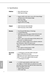
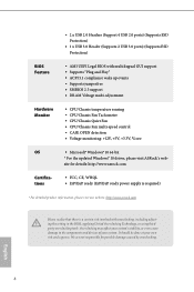
... SPEED LED) • HD Audio Jacks: Line in / Front Speaker / Microphone Storage • 4 x SATA3 6.0 Gb/s Connectors, support RAID (RAID 0, RAID 1 and RAID 10), NCQ, AHCI and Hot Plug* • 1 x Ultra M.2 Socket (M2_1), supports type 2242/2260/2280 M.2 SATA3 6.0 Gb/s module and M.2 PCI Express module up to Gen3 x4 (32 Gb/s) (with Ryzen Series CPU) or Gen3 x2 (16 Gb/s) (with A-Series APU)** ** Supports NVMe SSD as boot disks ** Supports ASRock U.2 Kit Connector • 1 x COM Port Header • 1 x TPM Header • 1 x Chassis...
... SPEED LED) • HD Audio Jacks: Line in / Front Speaker / Microphone Storage • 4 x SATA3 6.0 Gb/s Connectors, support RAID (RAID 0, RAID 1 and RAID 10), NCQ, AHCI and Hot Plug* • 1 x Ultra M.2 Socket (M2_1), supports type 2242/2260/2280 M.2 SATA3 6.0 Gb/s module and M.2 PCI Express module up to Gen3 x4 (32 Gb/s) (with Ryzen Series CPU) or Gen3 x2 (16 Gb/s) (with A-Series APU)** ** Supports NVMe SSD as boot disks ** Supports ASRock U.2 Kit Connector • 1 x COM Port Header • 1 x TPM Header • 1 x Chassis...
User Manual
Page 9
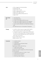
...8226; CPU/Chassis Fan multi-speed control • CASE OPEN detection • Voltage monitoring: +12V, +5V, +3.3V, Vcore OS • Microsoft® Windows® 10 64-bit * For the updated Windows® 10 driver, please visit ASRock's web- It should be done at your system. • 2 x USB 2.0 Headers (Support 4 USB 2.0 ports) (Supports ESD Protection) • 1 x USB 3.0 Header (Supports 2 USB 3.0 ports) (Supports ESD Protection) BIOS Feature • AMI UEFI Legal BIOS with overclocking, including adjusting the setting in the BIOS, applying Untied Overclocking Technology, or using...
...8226; CPU/Chassis Fan multi-speed control • CASE OPEN detection • Voltage monitoring: +12V, +5V, +3.3V, Vcore OS • Microsoft® Windows® 10 64-bit * For the updated Windows® 10 driver, please visit ASRock's web- It should be done at your system. • 2 x USB 2.0 Headers (Support 4 USB 2.0 ports) (Supports ESD Protection) • 1 x USB 3.0 Header (Supports 2 USB 3.0 ports) (Supports ESD Protection) BIOS Feature • AMI UEFI Legal BIOS with overclocking, including adjusting the setting in the BIOS, applying Untied Overclocking Technology, or using...

User Manual
Page 11
...-pin DDR4 DIMM Slots (DDR4_A1, DDR4_B1) 3 CPU Fan Connector (CPU_FAN1) 4 ATX Power Connector (ATXPWR1) 5 USB 3.0 Header (USB3_7_8) 6 USB 2.0 Header (USB_5_6) 7 USB 2.0 Header (USB_3_4) 8 SATA3 Connector (SATA3_3) 9 SATA3 Connector (SATA3_4) 10 SATA3 Connector (SATA3_2) 11 SATA3 Connector (SATA3_1) 12 System Panel Header (PANEL1) 13 Chassis Intrusion and Speaker Header (SPK_CI1) 14 Chassis Fan Connector (CHA_FAN2) 15 COM Port Header (COM1) 16 TPM Header (TPMS1) 17 RGB LED Header (RGB_LED1) 18 Clear CMOS Jumper (CLRCMOS1) 19 Chassis Fan Connector (CHA_FAN1) 20 Front Panel Audio Header (HD_AUDIO1...
...-pin DDR4 DIMM Slots (DDR4_A1, DDR4_B1) 3 CPU Fan Connector (CPU_FAN1) 4 ATX Power Connector (ATXPWR1) 5 USB 3.0 Header (USB3_7_8) 6 USB 2.0 Header (USB_5_6) 7 USB 2.0 Header (USB_3_4) 8 SATA3 Connector (SATA3_3) 9 SATA3 Connector (SATA3_4) 10 SATA3 Connector (SATA3_2) 11 SATA3 Connector (SATA3_1) 12 System Panel Header (PANEL1) 13 Chassis Intrusion and Speaker Header (SPK_CI1) 14 Chassis Fan Connector (CHA_FAN2) 15 COM Port Header (COM1) 16 TPM Header (TPMS1) 17 RGB LED Header (RGB_LED1) 18 Clear CMOS Jumper (CLRCMOS1) 19 Chassis Fan Connector (CHA_FAN1) 20 Front Panel Audio Header (HD_AUDIO1...

User Manual
Page 13
...-pin DDR4 DIMM Slots (DDR4_A1, DDR4_B1) 3 CPU Fan Connector (CPU_FAN1) 4 ATX Power Connector (ATXPWR1) 5 USB 3.0 Header (USB3_7_8) 6 USB 2.0 Header (USB_5_6) 7 USB 2.0 Header (USB_3_4) 8 SATA3 Connector (SATA3_3) 9 SATA3 Connector (SATA3_4) 10 SATA3 Connector (SATA3_2) 11 SATA3 Connector (SATA3_1) 12 System Panel Header (PANEL1) 13 Chassis Intrusion and Speaker Header (SPK_CI1) 14 Chassis Fan Connector (CHA_FAN2) 15 COM Port Header (COM1) 16 TPM Header (TPMS1) 17 RGB LED Header (RGB_LED1) 18 Clear CMOS Jumper (CLRCMOS1) 19 Chassis Fan Connector (CHA_FAN1) 20 Front Panel Audio Header (HD_AUDIO1...
...-pin DDR4 DIMM Slots (DDR4_A1, DDR4_B1) 3 CPU Fan Connector (CPU_FAN1) 4 ATX Power Connector (ATXPWR1) 5 USB 3.0 Header (USB3_7_8) 6 USB 2.0 Header (USB_5_6) 7 USB 2.0 Header (USB_3_4) 8 SATA3 Connector (SATA3_3) 9 SATA3 Connector (SATA3_4) 10 SATA3 Connector (SATA3_2) 11 SATA3 Connector (SATA3_1) 12 System Panel Header (PANEL1) 13 Chassis Intrusion and Speaker Header (SPK_CI1) 14 Chassis Fan Connector (CHA_FAN2) 15 COM Port Header (COM1) 16 TPM Header (TPMS1) 17 RGB LED Header (RGB_LED1) 18 Clear CMOS Jumper (CLRCMOS1) 19 Chassis Fan Connector (CHA_FAN1) 20 Front Panel Audio Header (HD_AUDIO1...

User Manual
Page 17
Chapter 2 Installation This is a Micro ATX form factor motherboard. Before you install the motherboard, study the configuration of the following precautions before you install motherboard components or change any components, place them on a carpet. Failure to do so may damage the motherboard. 12 English Doing so may cause physical injuries to you uninstall any motherboard settings. • Make sure to unplug the power cord before...
Chapter 2 Installation This is a Micro ATX form factor motherboard. Before you install the motherboard, study the configuration of the following precautions before you install motherboard components or change any components, place them on a carpet. Failure to do so may damage the motherboard. 12 English Doing so may cause physical injuries to you uninstall any motherboard settings. • Make sure to unplug the power cord before...

User Manual
Page 31
2.4 Expansion Slots (PCI Express Slots) There are 2 PCI Express slots on the motherboard. PCIe slots: PCIE1 (PCIe 2.0 x1 slot) is used for PCI Express x16 lane width graphics cards. * PCIE2 will downgrade to x8 mode when A-Series APU is installed. 26 English PCIE2 (PCIe 3.0 x16 slot) is unplugged. Please read the documentation of the expansion card and make sure that the power supply is switched off or the power cord is used for the card before you start the installation. Before installing an...
2.4 Expansion Slots (PCI Express Slots) There are 2 PCI Express slots on the motherboard. PCIe slots: PCIE1 (PCIe 2.0 x1 slot) is used for PCI Express x16 lane width graphics cards. * PCIE2 will downgrade to x8 mode when A-Series APU is installed. 26 English PCIE2 (PCIe 3.0 x16 slot) is unplugged. Please read the documentation of the expansion card and make sure that the power supply is switched off or the power cord is used for the card before you start the installation. Before installing an...

User Manual
Page 32
.... Please adjust the BIOS option "Clear Status" to default setup, please turn off the computer and unplug the power cord from the power supply. English 27 However, please do the clear-CMOS action. When the jumper cap is placed on the pins, the jumper is removed. Clear CMOS Jumper (CLRMOS1) (see p.5 or 7, No. 18) Default Clear CMOS CLRMOS1 allows you update the BIOS. After waiting for 15 seconds, use a jumper cap to clear the data in...
.... Please adjust the BIOS option "Clear Status" to default setup, please turn off the computer and unplug the power cord from the power supply. English 27 However, please do the clear-CMOS action. When the jumper cap is placed on the pins, the jumper is removed. Clear CMOS Jumper (CLRMOS1) (see p.5 or 7, No. 18) Default Clear CMOS CLRMOS1 allows you update the BIOS. After waiting for 15 seconds, use a jumper cap to clear the data in...

User Manual
Page 33
... header according to the power switch on the chassis front panel. A front panel module mainly consists of power switch, reset switch, power LED, hard drive activity LED, speaker and etc. Do NOT place jumper caps over the headers and connectors will cause permanent damage to this header, make sure the wire assignments and the pin assignments are NOT jumpers. HDLED (Hard Drive Activity LED): Connect to the power status indicator on the chassis front panel. 2.6 Onboard Headers and Connectors Onboard headers and connectors are matched correctly. System Panel Header (9-pin...
... header according to the power switch on the chassis front panel. A front panel module mainly consists of power switch, reset switch, power LED, hard drive activity LED, speaker and etc. Do NOT place jumper caps over the headers and connectors will cause permanent damage to this header, make sure the wire assignments and the pin assignments are NOT jumpers. HDLED (Hard Drive Activity LED): Connect to the power status indicator on the chassis front panel. 2.6 Onboard Headers and Connectors Onboard headers and connectors are matched correctly. System Panel Header (9-pin...

User Manual
Page 35
... connect fan cables to the fan connectors and match the black wire to MIC2_L. CPU Fan Connector FAN_SPEED This motherboard pro- Please follow the instructions in the Realtek Control panel and adjust "Recording Volume". D. If you use a 20-pin ATX power supply, please plug it along Pin 1 and Pin 13. MIC_RET and OUT_RET are for the AC'97 audio panel. C. High Definition Audio supports Jack Sensing, but the panel wire on the chassis must support HDA to connect them for the HD audio panel...
... connect fan cables to the fan connectors and match the black wire to MIC2_L. CPU Fan Connector FAN_SPEED This motherboard pro- Please follow the instructions in the Realtek Control panel and adjust "Recording Volume". D. If you use a 20-pin ATX power supply, please plug it along Pin 1 and Pin 13. MIC_RET and OUT_RET are for the AC'97 audio panel. C. High Definition Audio supports Jack Sensing, but the panel wire on the chassis must support HDA to connect them for the HD audio panel...

User Manual
Page 36
... for for further instructions on these two headers. otherwise, the cable may be damaged. *Please refer to connect RGB LED extension cable which can securely store keys, digital certificates, passwords, and data. To use a 4-pin ATX power supply, please plug it along Pin 1 and Pin 5. ATX 12V Power Connector (8-pin ATX12V1) (see p.5 or 7, No. 1) Serial Port Header (9-pin COM1) (see p.5 or 7, No. 15) TPM Header (17-pin TPMS1) (see p.5 or 7, No. 16) RGB LED Header (4-pin RGB_LED1) (see p.5 or...
... for for further instructions on these two headers. otherwise, the cable may be damaged. *Please refer to connect RGB LED extension cable which can securely store keys, digital certificates, passwords, and data. To use a 4-pin ATX power supply, please plug it along Pin 1 and Pin 5. ATX 12V Power Connector (8-pin ATX12V1) (see p.5 or 7, No. 1) Serial Port Header (9-pin COM1) (see p.5 or 7, No. 15) TPM Header (17-pin TPMS1) (see p.5 or 7, No. 16) RGB LED Header (4-pin RGB_LED1) (see p.5 or...
User Manual
Page 41
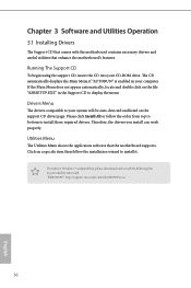
... Windows 7 compatibility, please download and install the following hot fix provided by Microsoft. Please click Install All or follow the installation wizard to display the menu. Therefore, the drivers you install can work properly. Chapter 3 Software and Utilities Operation 3.1 Installing Drivers The Support CD that comes with the motherboard contains necessary drivers and useful utilities that the motherboard supports. Running The Support CD To begin using the support CD, insert the CD into your CD-ROM drive...
... Windows 7 compatibility, please download and install the following hot fix provided by Microsoft. Please click Install All or follow the installation wizard to display the menu. Therefore, the drivers you install can work properly. Chapter 3 Software and Utilities Operation 3.1 Installing Drivers The Support CD that comes with the motherboard contains necessary drivers and useful utilities that the motherboard supports. Running The Support CD To begin using the support CD, insert the CD into your CD-ROM drive...

User Manual
Page 50
...chassis. Because the UEFI software is constantly being updated, the following selections: Main For setting system time/date information OC Tweaker For overclocking configurations Advanced For advanced system configurations Tool Useful tools H/W Monitor Displays current hardware status Security For security settings Boot For configuring boot settings and boot priority Exit Exit the current screen or the UEFI Setup Utility English 45 AB350M A320M Chapter 4 UEFI SETUP UTILITY 4.1 Introduction This section explains how to use the UEFI SETUP UTILITY to enter the UEFI SETUP...
...chassis. Because the UEFI software is constantly being updated, the following selections: Main For setting system time/date information OC Tweaker For overclocking configurations Advanced For advanced system configurations Tool Useful tools H/W Monitor Displays current hardware status Security For security settings Boot For configuring boot settings and boot priority Exit Exit the current screen or the UEFI Setup Utility English 45 AB350M A320M Chapter 4 UEFI SETUP UTILITY 4.1 Introduction This section explains how to use the UEFI SETUP UTILITY to enter the UEFI SETUP...

User Manual
Page 55
... to enable or disable AMD's Cool 'n' QuietTM technology. AMD fTPM Switch Use this item to enable or disable Core C6 mode. Please note that enabling this option is [Enabled]. SVM Mode When this function may reduce CPU voltage and memory frequency, and lead to system stability or compatibility issue with some memory modules or power supplies. The default value is set to [Enabled], a VMM (Virtual Machine Architecture) can utilize the additional hardware capabilities provided by AMD-V. 4.4.1 CPU Configuration Cool 'n' Quiet Use this...
... to enable or disable AMD's Cool 'n' QuietTM technology. AMD fTPM Switch Use this item to enable or disable Core C6 mode. Please note that enabling this option is [Enabled]. SVM Mode When this function may reduce CPU voltage and memory frequency, and lead to system stability or compatibility issue with some memory modules or power supplies. The default value is set to [Enabled], a VMM (Virtual Machine Architecture) can utilize the additional hardware capabilities provided by AMD-V. 4.4.1 CPU Configuration Cool 'n' Quiet Use this...

User Manual
Page 58
RAID: Combine multiple disk drives into a logical unit. 53 English 4.4.4 Storage Configuration AB350M A320M SATA Controller(s) Enable/disable the SATA controllers. SATA Mode AHCI: Supports new features that improve performance.
RAID: Combine multiple disk drives into a logical unit. 53 English 4.4.4 Storage Configuration AB350M A320M SATA Controller(s) Enable/disable the SATA controllers. SATA Mode AHCI: Supports new features that improve performance.

User Manual
Page 62
English 57 After copying the drivers please change the SATA mode to your liking. Easy RAID Installer Easy RAID Installer helps you to copy the RAID driver from the support CD to RAID, then you to adjust the RGB LED color to your USB storage device. 4.5 Tools AB350M A320M RGB LED ASRock RGB LED allows you can start installing the operating system in RAID mode.
English 57 After copying the drivers please change the SATA mode to your liking. Easy RAID Installer Easy RAID Installer helps you to copy the RAID driver from the support CD to RAID, then you to adjust the RGB LED color to your USB storage device. 4.5 Tools AB350M A320M RGB LED ASRock RGB LED allows you can start installing the operating system in RAID mode.
User Manual
Page 63
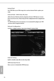
Network Configuration Use this function. Please setup network configuration before using Internet Flash. *For BIOS backup and recovery purpose, it is recommended to plug in the setup utility. DHCP (Auto IP), Auto ASRock Internet Flash downloads and updates the latest UEFI firmware version from our servers for Internet Flash. UEFI Download Server Select a server to download the UEFI firmware. 58 English Internet Setting Enable or disable sound effects in your UEFI. Instant Flash Save UEFI files in your USB storage device and run Instant Flash to update your USB pen drive before...
Network Configuration Use this function. Please setup network configuration before using Internet Flash. *For BIOS backup and recovery purpose, it is recommended to plug in the setup utility. DHCP (Auto IP), Auto ASRock Internet Flash downloads and updates the latest UEFI firmware version from our servers for Internet Flash. UEFI Download Server Select a server to download the UEFI firmware. 58 English Internet Setting Enable or disable sound effects in your UEFI. Instant Flash Save UEFI files in your USB storage device and run Instant Flash to update your USB pen drive before...

User Manual
Page 64
AB350M A320M 4.6 Hardware Health Event Monitoring Screen This section allows you to set 5 CPU temperatures and assign a respective fan speed for each temperature. Chassis Fan 1 Setting Select a fan mode for each temperature. Case Open Feature Enable or disable Case Open Feature to set 5 CPU temperatures and assign a respective fan speed for Chassis Fan 1, or choose Customize to monitor the status of the hardware on your system, including the parameters of the CPU temperature, motherboard temperature, fan speed and voltage. Over Temperature Protection When Over Temperature Protection...
AB350M A320M 4.6 Hardware Health Event Monitoring Screen This section allows you to set 5 CPU temperatures and assign a respective fan speed for each temperature. Chassis Fan 1 Setting Select a fan mode for each temperature. Case Open Feature Enable or disable Case Open Feature to set 5 CPU temperatures and assign a respective fan speed for Chassis Fan 1, or choose Customize to monitor the status of the hardware on your system, including the parameters of the CPU temperature, motherboard temperature, fan speed and voltage. Over Temperature Protection When Over Temperature Protection...


