
User Manual
Page 4
... 1 1.1 Package Contents 1 1.2 Specifications 2 1.3 Motherboard Layout 6 1.4 I/O Panel 9 Chapter 2 Installation 12 2.1 Installing the CPU 13 2.2 Installing the CPU Fan and Heatsink 15 2.3 Installing Memory Modules (DIMM) 23 2.4 Expansion Slots (PCI Express Slots) 25 2.5 Jumpers Setup 26 2.6 Onboard Headers and Connectors 27 2.7 M.2_SSD (NGFF) Module Installation Guide 31 Chapter 3 Software and Utilities Operation 35 3.1 Installing Drivers 35 3.2 ASRock Live Update & APP Shop 36 3.2.1 UI Overview 36 3.2.2 Apps 37 3.2.3 BIOS & Drivers 40 3.2.4 Setting 41
... 1 1.1 Package Contents 1 1.2 Specifications 2 1.3 Motherboard Layout 6 1.4 I/O Panel 9 Chapter 2 Installation 12 2.1 Installing the CPU 13 2.2 Installing the CPU Fan and Heatsink 15 2.3 Installing Memory Modules (DIMM) 23 2.4 Expansion Slots (PCI Express Slots) 25 2.5 Jumpers Setup 26 2.6 Onboard Headers and Connectors 27 2.7 M.2_SSD (NGFF) Module Installation Guide 31 Chapter 3 Software and Utilities Operation 35 3.1 Installing Drivers 35 3.2 ASRock Live Update & APP Shop 36 3.2.1 UI Overview 36 3.2.2 Apps 37 3.2.3 BIOS & Drivers 40 3.2.4 Setting 41
User Manual
Page 6
.../A320M-HDV/A320M-DGS Motherboard (Micro ATX Form Factor) • ASRock AB350M-HDV/A320M-HDV/A320M-DGS Quick Installation Guide • ASRock AB350M-HDV/A320M-HDV/A320M-DGS Support CD • 2 x Serial ATA (SATA) Data Cables (Optional) • 1 x I/O Panel Shield 1 English If you are using. AB350M-HDV/A320M-HDV/A320M-DGS Chapter 1 Introduction Thank you for specific information about the model you require technical support related to this manual will be subject to quality and endurance. Chapter 4 contains the configuration guide...
.../A320M-HDV/A320M-DGS Motherboard (Micro ATX Form Factor) • ASRock AB350M-HDV/A320M-HDV/A320M-DGS Quick Installation Guide • ASRock AB350M-HDV/A320M-HDV/A320M-DGS Support CD • 2 x Serial ATA (SATA) Data Cables (Optional) • 1 x I/O Panel Shield 1 English If you are using. AB350M-HDV/A320M-HDV/A320M-DGS Chapter 1 Introduction Thank you for specific information about the model you require technical support related to this manual will be subject to quality and endurance. Chapter 4 contains the configuration guide...
User Manual
Page 7
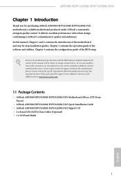
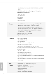
... system memory: 32GB • 15μ Gold Contact in DIMM Slots Expansion Slot • 1 x PCI Express 3.0 x16 Slot (PCIE2 @ x16 mode)* * Supports NVMe SSD as boot disks * AMD Ryzen series CPUs support PCIE2: x16 mode * AMD 7th A-Series APUs support PCIE2: x8 mode • 1 x PCI Express 2.0 x1 Slot Graphics • Integrated AMD RadeonTM R7 Series Graphics in A-series / E-series APU • DirectX 12, Pixel Shader 5.0 • Max. 1.2 Specifications Platform • Micro ATX Form Factor • Solid Capacitor design CPU • Supports AMD Socket AM4 A-Series...
... system memory: 32GB • 15μ Gold Contact in DIMM Slots Expansion Slot • 1 x PCI Express 3.0 x16 Slot (PCIE2 @ x16 mode)* * Supports NVMe SSD as boot disks * AMD Ryzen series CPUs support PCIE2: x16 mode * AMD 7th A-Series APUs support PCIE2: x8 mode • 1 x PCI Express 2.0 x1 Slot Graphics • Integrated AMD RadeonTM R7 Series Graphics in A-series / E-series APU • DirectX 12, Pixel Shader 5.0 • Max. 1.2 Specifications Platform • Micro ATX Form Factor • Solid Capacitor design CPU • Supports AMD Socket AM4 A-Series...
User Manual
Page 8
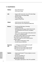
...) playback with DVI-D and HDMI Ports A320M-DGS: • Supports DVI-D with max. resolution up to use an HD front panel audio module and enable the multi-channel audio feature through the audio driver. • Supports Surge Protection • ELNA Audio Caps LAN • PCIE x1 Gigabit LAN 10/100/1000 Mb/s • Realtek RTL8111GR • Supports Wake-On-LAN • Supports Lightning/ESD Protection • Supports LAN Cable Detection • Supports Energy Efficient Ethernet 802.3az...
...) playback with DVI-D and HDMI Ports A320M-DGS: • Supports DVI-D with max. resolution up to use an HD front panel audio module and enable the multi-channel audio feature through the audio driver. • Supports Surge Protection • ELNA Audio Caps LAN • PCIE x1 Gigabit LAN 10/100/1000 Mb/s • Realtek RTL8111GR • Supports Wake-On-LAN • Supports Lightning/ESD Protection • Supports LAN Cable Detection • Supports Energy Efficient Ethernet 802.3az...
User Manual
Page 9
... Speaker Header • 1 x CPU Fan Connector (4-pin) • 2 x Chassis Fan Connectors (1 x 4-pin, 1 x 3-pin) * The CPU Fan Connector supports the CPU fan of maximum 1A (12W) fan power. • 1 x 24 pin ATX Power Connector • 1 x 4 pin 12V Power Connector • 1 x Front Panel Audio Connector • 2 x USB 2.0 Headers (Support 4 USB 2.0 ports) (Supports ESD Protection) • 1 x USB 3.0 Header (Supports 2 USB 3.0 ports) (Supports ESD Protection) English BIOS Feature • AMI UEFI Legal BIOS with GUI support • Supports "Plug and Play" • ACPI 5.1 compliance wake...
... Speaker Header • 1 x CPU Fan Connector (4-pin) • 2 x Chassis Fan Connectors (1 x 4-pin, 1 x 3-pin) * The CPU Fan Connector supports the CPU fan of maximum 1A (12W) fan power. • 1 x 24 pin ATX Power Connector • 1 x 4 pin 12V Power Connector • 1 x Front Panel Audio Connector • 2 x USB 2.0 Headers (Support 4 USB 2.0 ports) (Supports ESD Protection) • 1 x USB 3.0 Header (Supports 2 USB 3.0 ports) (Supports ESD Protection) English BIOS Feature • AMI UEFI Legal BIOS with GUI support • Supports "Plug and Play" • ACPI 5.1 compliance wake...
User Manual
Page 10
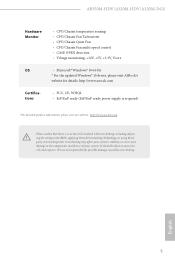
... overclocking, including adjusting the setting in the BIOS, applying Untied Overclocking Technology, or using thirdparty overclocking tools. It should be done at your system. AB350M-HDV/A320M-HDV/A320M-DGS Hardware Monitor • CPU/Chassis temperature sensing • CPU/Chassis Fan Tachometer • CPU/Chassis Quiet Fan • CPU/Chassis Fan multi-speed control • CASE OPEN detection • Voltage monitoring: +12V, +5V, +3.3V, Vcore OS • Microsoft® Windows® 10 64-bit * For the updated Windows® 10 driver, please visit ASRock...
... overclocking, including adjusting the setting in the BIOS, applying Untied Overclocking Technology, or using thirdparty overclocking tools. It should be done at your system. AB350M-HDV/A320M-HDV/A320M-DGS Hardware Monitor • CPU/Chassis temperature sensing • CPU/Chassis Fan Tachometer • CPU/Chassis Quiet Fan • CPU/Chassis Fan multi-speed control • CASE OPEN detection • Voltage monitoring: +12V, +5V, +3.3V, Vcore OS • Microsoft® Windows® 10 64-bit * For the updated Windows® 10 driver, please visit ASRock...

User Manual
Page 13
... ATX 12V Power Connector (ATX12V1) 2 CPU Fan Connector (CPU_FAN1) 3 2 x 288-pin DDR4 DIMM Slots (DDR4_A1, DDR4_A2) 4 ATX Power Connector (ATXPWR1) 5 USB 3.0 Header (USB3_5_6) 6 USB 2.0 Header (USB_3_4) 7 USB 2.0 Header (USB_5_6) 8 SATA3 Connector (SATA3_3) 9 SATA3 Connector (SATA3_4) 10 SATA3 Connector (SATA3_1) 11 SATA3 Connector (SATA3_2) 12 Clear CMOS Jumper (CLRCMOS1) 13 System Panel Header (PANEL1) 14 Chassis Intrusion and Speaker Header (SPK_CI1) 15 Chassis Fan Connector (CHA_FAN2) 16 Print Port Header (LPT1) 17 COM Port Header (COM1) 18 Front Panel Audio Header (HD_AUDIO1) 19 TPM Header...
... ATX 12V Power Connector (ATX12V1) 2 CPU Fan Connector (CPU_FAN1) 3 2 x 288-pin DDR4 DIMM Slots (DDR4_A1, DDR4_A2) 4 ATX Power Connector (ATXPWR1) 5 USB 3.0 Header (USB3_5_6) 6 USB 2.0 Header (USB_3_4) 7 USB 2.0 Header (USB_5_6) 8 SATA3 Connector (SATA3_3) 9 SATA3 Connector (SATA3_4) 10 SATA3 Connector (SATA3_1) 11 SATA3 Connector (SATA3_2) 12 Clear CMOS Jumper (CLRCMOS1) 13 System Panel Header (PANEL1) 14 Chassis Intrusion and Speaker Header (SPK_CI1) 15 Chassis Fan Connector (CHA_FAN2) 16 Print Port Header (LPT1) 17 COM Port Header (COM1) 18 Front Panel Audio Header (HD_AUDIO1) 19 TPM Header...

User Manual
Page 17
... static electricity to the chassis, please do so may damage the motherboard. 12 English Doing so may cause physical injuries to do not overtighten the screws! Chapter 2 Installation This is a Micro ATX form factor motherboard. Before you install the motherboard, study the configuration of the following precautions before installing or removing the motherboard. Failure to you install motherboard components or change any components, place them...
... static electricity to the chassis, please do so may damage the motherboard. 12 English Doing so may cause physical injuries to do not overtighten the screws! Chapter 2 Installation This is a Micro ATX form factor motherboard. Before you install the motherboard, study the configuration of the following precautions before installing or removing the motherboard. Failure to you install motherboard components or change any components, place them...
User Manual
Page 28
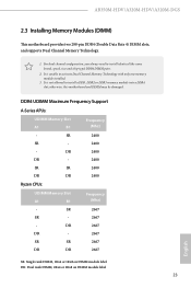
AB350M-HDV/A320M-HDV/A320M-DGS 2.3 Installing Memory Modules (DIMM) This motherboard provides two 288-pin DDR4 (Double Data Rate 4) DIMM slots, and supports Dual Channel Memory Technology. 1. For dual channel configuration, you always need to install a DDR, DDR2 or DDR3 memory module into a DDR4 slot; SR 2667 SR - 2667 - It is unable to activate Dual Channel Memory Technology with only one memory module installed. 3. DDR4 UDIMM Maximum Frequency Support A-Series APUs: UDIMM Memory Slot A1 B1 Frequency (Mhz) - SR 2400 SR...
AB350M-HDV/A320M-HDV/A320M-DGS 2.3 Installing Memory Modules (DIMM) This motherboard provides two 288-pin DDR4 (Double Data Rate 4) DIMM slots, and supports Dual Channel Memory Technology. 1. For dual channel configuration, you always need to install a DDR, DDR2 or DDR3 memory module into a DDR4 slot; SR 2667 SR - 2667 - It is unable to activate Dual Channel Memory Technology with only one memory module installed. 3. DDR4 UDIMM Maximum Frequency Support A-Series APUs: UDIMM Memory Slot A1 B1 Frequency (Mhz) - SR 2400 SR...

User Manual
Page 30
... hardware settings for PCI Express x16 lane width graphics cards. * PCIE2 will downgrade to x8 mode when A-Series APU is installed. 25 English AB350M-HDV/A320M-HDV/A320M-DGS 2.4 Expansion Slots (PCI Express Slots) There are 2 PCI Express slots on the motherboard. PCIe slots: PCIE1 (PCIe 2.0 x1 slot) is used for the card before you start the installation. Please read the documentation of the expansion card and make sure that the power supply is switched off or the power cord is used for PCI Express...
... hardware settings for PCI Express x16 lane width graphics cards. * PCIE2 will downgrade to x8 mode when A-Series APU is installed. 25 English AB350M-HDV/A320M-HDV/A320M-DGS 2.4 Expansion Slots (PCI Express Slots) There are 2 PCI Express slots on the motherboard. PCIe slots: PCIE1 (PCIe 2.0 x1 slot) is used for the card before you start the installation. Please read the documentation of the expansion card and make sure that the power supply is switched off or the power cord is used for PCI Express...

User Manual
Page 31
... to short pin2 and pin3 on the pins, the jumper is "Open". The illustration shows a 3-pin jumper whose pin1 and pin2 are setup. Please adjust the BIOS option "Clear Status" to clear the data in CMOS. To clear and reset the system parameters to default setup, please turn off the computer and unplug the power cord from the power supply. Please be noted that the password, date, time, and user default profile...
... to short pin2 and pin3 on the pins, the jumper is "Open". The illustration shows a 3-pin jumper whose pin1 and pin2 are setup. Please adjust the BIOS option "Clear Status" to clear the data in CMOS. To clear and reset the system parameters to default setup, please turn off the computer and unplug the power cord from the power supply. Please be noted that the password, date, time, and user default profile...
User Manual
Page 32
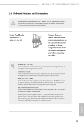
... panel design may configure the way to turn off your chassis front panel module to this header according to the hard drive activity LED on when the system is on the chassis front panel. A front panel module mainly consists of power switch, reset switch, power LED, hard drive activity LED, speaker and etc. The LED is off (S5). AB350M-HDV/A320M-HDV/A320M-DGS 2.6 Onboard Headers and Connectors Onboard headers and connectors are matched correctly. Note the positive and negative pins before connecting the cables. System Panel Header (9-pin...
... panel design may configure the way to turn off your chassis front panel module to this header according to the hard drive activity LED on when the system is on the chassis front panel. A front panel module mainly consists of power switch, reset switch, power LED, hard drive activity LED, speaker and etc. The LED is off (S5). AB350M-HDV/A320M-HDV/A320M-DGS 2.6 Onboard Headers and Connectors Onboard headers and connectors are matched correctly. Note the positive and negative pins before connecting the cables. System Panel Header (9-pin...
User Manual
Page 34
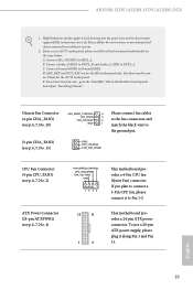
... the instructions in the Realtek Control panel and adjust "Recording Volume". If you use a 20-pin ATX power supply, please plug it along Pin 1 and Pin 13. E. D. High Definition Audio supports Jack Sensing, but the panel wire on the chassis must support HDA to Ground (GND). C. AB350M-HDV/A320M-HDV/A320M-DGS 1. You don't need to Pin 1-3. Connect Ground (GND) to function correctly. If you plan to connect a 3-Pin CPU fan, please connect it to the ground pin. (3-pin CHA_FAN2...
... the instructions in the Realtek Control panel and adjust "Recording Volume". If you use a 20-pin ATX power supply, please plug it along Pin 1 and Pin 13. E. D. High Definition Audio supports Jack Sensing, but the panel wire on the chassis must support HDA to Ground (GND). C. AB350M-HDV/A320M-HDV/A320M-DGS 1. You don't need to Pin 1-3. Connect Ground (GND) to function correctly. If you plan to connect a 3-Pin CPU fan, please connect it to the ground pin. (3-pin CHA_FAN2...
User Manual
Page 40
... Drivers Menu The drivers compatible to install those required drivers. Click on a specific item then follow the order from top to bottom to your system will be auto-detected and listed on the file "ASRSETUP.EXE" in your CD-ROM drive. Running The Support CD To begin using the support CD, insert the CD into your computer. Therefore, the drivers you install can work properly. The CD automatically displays...
... Drivers Menu The drivers compatible to install those required drivers. Click on a specific item then follow the order from top to bottom to your system will be auto-detected and listed on the file "ASRSETUP.EXE" in your CD-ROM drive. Running The Support CD To begin using the support CD, insert the CD into your computer. Therefore, the drivers you install can work properly. The CD automatically displays...

User Manual
Page 47
... the UEFI software is constantly being updated, the following selections: Main For setting system time/date information OC Tweaker For overclocking configurations Advanced For advanced system configurations Tool Useful tools H/W Monitor Displays current hardware status Boot For configuring boot settings and boot priority Security For security settings Exit Exit the current screen or the UEFI Setup Utility English 42 You may also restart by pressing the reset button on the computer, otherwise, the Power...
... the UEFI software is constantly being updated, the following selections: Main For setting system time/date information OC Tweaker For overclocking configurations Advanced For advanced system configurations Tool Useful tools H/W Monitor Displays current hardware status Boot For configuring boot settings and boot priority Security For security settings Exit Exit the current screen or the UEFI Setup Utility English 42 You may also restart by pressing the reset button on the computer, otherwise, the Power...

User Manual
Page 52
... provided by AMD-V. Configuration options: [Enabled] and [Disabled]. SVM Mode When this option is [Enabled]. 47 English Please note that enabling this function may reduce CPU voltage and memory frequency, and lead to enable or disable AMD's Cool 'n' QuietTM technology. Configuration options: [Enabled] and [Disabled]. The default value is set this item to [Enabled]. 4.4.1 CPU Configuration AB350M-HDV/A320M-HDV/A320M-DGS Cool 'n' Quiet Use this item to system stability or compatibility issue with some memory modules or power supplies. If you install Windows® OS...
... provided by AMD-V. Configuration options: [Enabled] and [Disabled]. SVM Mode When this option is [Enabled]. 47 English Please note that enabling this function may reduce CPU voltage and memory frequency, and lead to enable or disable AMD's Cool 'n' QuietTM technology. Configuration options: [Enabled] and [Disabled]. The default value is set this item to [Enabled]. 4.4.1 CPU Configuration AB350M-HDV/A320M-HDV/A320M-DGS Cool 'n' Quiet Use this item to system stability or compatibility issue with some memory modules or power supplies. If you install Windows® OS...

User Manual
Page 56
Change Settings Select the address of the Serial port. Device Mode Select the device mode according to Auto. 51 English Serial Port Address Select the address of the Parallel port. Parallel Port Enable or disable the Parallel port. AB350M-HDV/A320M-HDV/A320M-DGS 4.4.5 Super IO Configuration Serial Port Enable or disable the Serial port. PS2 Y-Cable Enable the PS2 Y-Cable or set this option to your connected device.
Change Settings Select the address of the Serial port. Device Mode Select the device mode according to Auto. 51 English Serial Port Address Select the address of the Parallel port. Parallel Port Enable or disable the Parallel port. AB350M-HDV/A320M-HDV/A320M-DGS 4.4.5 Super IO Configuration Serial Port Enable or disable the Serial port. PS2 Y-Cable Enable the PS2 Y-Cable or set this option to your connected device.
User Manual
Page 59
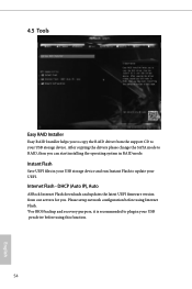
... start installing the operating system in RAID mode. Instant Flash Save UEFI files in your USB pen drive before using Internet Flash. *For BIOS backup and recovery purpose, it is recommended to RAID, then you . Please setup network configuration before using this function. 54 English DHCP (Auto IP), Auto ASRock Internet Flash downloads and updates the latest UEFI firmware version from the support CD to your UEFI. After copying the drivers please change the SATA mode to plug in your USB storage device and run Instant Flash to update...
... start installing the operating system in RAID mode. Instant Flash Save UEFI files in your USB pen drive before using Internet Flash. *For BIOS backup and recovery purpose, it is recommended to RAID, then you . Please setup network configuration before using this function. 54 English DHCP (Auto IP), Auto ASRock Internet Flash downloads and updates the latest UEFI firmware version from the support CD to your UEFI. After copying the drivers please change the SATA mode to plug in your USB storage device and run Instant Flash to update...

User Manual
Page 60
UEFI Download Server Select a server to configure internet connection settings for Internet Flash. AB350M-HDV/A320M-HDV/A320M-DGS Network Configuration Use this to download the UEFI firmware. 55 English Internet Setting Enable or disable sound effects in the setup utility.
UEFI Download Server Select a server to configure internet connection settings for Internet Flash. AB350M-HDV/A320M-HDV/A320M-DGS Network Configuration Use this to download the UEFI firmware. 55 English Internet Setting Enable or disable sound effects in the setup utility.

User Manual
Page 61
... a fan mode for CPU Fan 1, or choose Customize to set 5 CPU temperatures and assign a respective fan speed for each temperature. Over Temperature Protection When Over Temperature Protection is enabled, the system automatically shuts down when the motherboard is overheated. Chassis Fan 1 Temp Source Select a fan temperature source for each temperature. 4.6 Hardware Health Event Monitoring Screen This section allows you to detect whether the chassis cover has been removed. 56 English Case Open Feature Enable or disable Case...
... a fan mode for CPU Fan 1, or choose Customize to set 5 CPU temperatures and assign a respective fan speed for each temperature. Over Temperature Protection When Over Temperature Protection is enabled, the system automatically shuts down when the motherboard is overheated. Chassis Fan 1 Temp Source Select a fan temperature source for each temperature. 4.6 Hardware Health Event Monitoring Screen This section allows you to detect whether the chassis cover has been removed. 56 English Case Open Feature Enable or disable Case...


