User Manual
Page 3
...Heatsink and CPU fan 15 2.5 Installation of Memory Modules (DIMM 16 2.6 Expansion Slots (PCI and PCI Express Slots 17 2.7 Jumpers Setup 18 2.8 Onboard Headers and Connectors 19 2.9 SATAII Hard Disk Setup Guide 23 2.10 Serial ATA (SATA) / Serial ATAII (SATAII) Hard Disks Installation 24 2.11 Driver Installation Guide 24 2.12 Untied Overclocking Technology 24 3 BIOS SETUP UTILITY 25 3.1 Introduction 25 3.1.1 BIOS Menu Bar 25 3.1.2 Navigation Keys 26 3.2 Main Screen 26 3.3 Smart Screen 27 3.4 Advanced Screen 28 3.4.1 CPU Configuration 28 3.4.2 Chipset Configuration 30 3.4.3 ACPI...
...Heatsink and CPU fan 15 2.5 Installation of Memory Modules (DIMM 16 2.6 Expansion Slots (PCI and PCI Express Slots 17 2.7 Jumpers Setup 18 2.8 Onboard Headers and Connectors 19 2.9 SATAII Hard Disk Setup Guide 23 2.10 Serial ATA (SATA) / Serial ATAII (SATAII) Hard Disks Installation 24 2.11 Driver Installation Guide 24 2.12 Untied Overclocking Technology 24 3 BIOS SETUP UTILITY 25 3.1 Introduction 25 3.1.1 BIOS Menu Bar 25 3.1.2 Navigation Keys 26 3.2 Main Screen 26 3.3 Smart Screen 27 3.4 Advanced Screen 28 3.4.1 CPU Configuration 28 3.4.2 Chipset Configuration 30 3.4.3 ACPI...
User Manual
Page 7
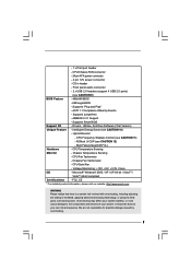
... ATX power connector - 4 pin 12V power connector - Front panel audio connector - 2 x USB 2.0 headers (support 4 USB 2.0 ports) (see CAUTION 12) - Supports Smart BIOS Support CD - Hybrid Booster: - ASRock U-COP (see CAUTION 9) BIOS Feature - 4Mb AMI BIOS - CPU Fan Tachometer - AMBIOS 2.3.1 Support - Boot Failure Guard (B.F.G.) Hardware - Chassis Temperature Sensing - - 1 x Print port header - CD in the BIOS, applying Untied Overclocking Technology, or using the thirdparty overclocking tools. ACPI 1.1 Compliance Wake Up Events - Voltage Monitoring...
... ATX power connector - 4 pin 12V power connector - Front panel audio connector - 2 x USB 2.0 headers (support 4 USB 2.0 ports) (see CAUTION 12) - Supports Smart BIOS Support CD - Hybrid Booster: - ASRock U-COP (see CAUTION 9) BIOS Feature - 4Mb AMI BIOS - CPU Fan Tachometer - AMBIOS 2.3.1 Support - Boot Failure Guard (B.F.G.) Hardware - Chassis Temperature Sensing - - 1 x Print port header - CD in the BIOS, applying Untied Overclocking Technology, or using the thirdparty overclocking tools. ACPI 1.1 Compliance Wake Up Events - Voltage Monitoring...
User Manual
Page 8
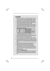
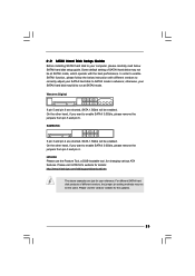
... information. 8. This motherboard supports Untied Overclocking Technology. Please check the table below for USB 2.0 works fine under Windows® XP, Windows® XP 64-bit, Windows® VistaTM and Windows® VistaTM 64-bit. 7. The maximum shared memory size is defined by the chipset vendor and is not recommended to SATAII connector, please read "Untied Overclocking Technology" on page 16 for proper jumper settings. 2. Power Management for the CPU FSB frequency and its...
... information. 8. This motherboard supports Untied Overclocking Technology. Please check the table below for USB 2.0 works fine under Windows® XP, Windows® XP 64-bit, Windows® VistaTM and Windows® VistaTM 64-bit. 7. The maximum shared memory size is defined by the chipset vendor and is not recommended to SATAII connector, please read "Untied Overclocking Technology" on page 16 for proper jumper settings. 2. Power Management for the CPU FSB frequency and its...
User Manual
Page 10
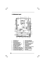
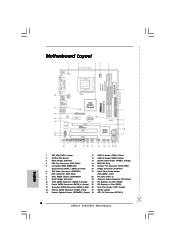
... 1 945GCM-S SATAII_2 SATAII_4 7 8 9 10 11 21 20 19 18 17 16 15 14 13 12 1 PS2_USB_PWR1 Jumper 15 USB 2.0 Header (USB6_7, Blue) 2 775-Pin CPU Socket 16 USB 2.0 Header (USB4_5, Blue) 3 North Bridge Controller 17 System Panel Header (PANEL1, Orange) 4 CPU Fan Connector (CPU_FAN1) 18 BIOS SPI Chip 5 2 x 240-pin DDR2 DIMM Slots 19 Chassis Fan Connector (CHA_FAN1) (Dual Channel: DDRII_1, DDRII_2; Red) 26 Print Port Header (LPT1, Purple) 13 Primary SATAII Connector (SATAII_1; Orange) 25 PCI Express x1 Slot...
... 1 945GCM-S SATAII_2 SATAII_4 7 8 9 10 11 21 20 19 18 17 16 15 14 13 12 1 PS2_USB_PWR1 Jumper 15 USB 2.0 Header (USB6_7, Blue) 2 775-Pin CPU Socket 16 USB 2.0 Header (USB4_5, Blue) 3 North Bridge Controller 17 System Panel Header (PANEL1, Orange) 4 CPU Fan Connector (CPU_FAN1) 18 BIOS SPI Chip 5 2 x 240-pin DDR2 DIMM Slots 19 Chassis Fan Connector (CHA_FAN1) (Dual Channel: DDRII_1, DDRII_2; Red) 26 Print Port Header (LPT1, Purple) 13 Primary SATAII Connector (SATAII_1; Orange) 25 PCI Express x1 Slot...
User Manual
Page 23
... remove the jumpers from pin 5 and pin 6. Some default setting of different vendors, the jumper pin setting methods may not be at SATAII mode. Please visit HITACHI's website for your reference. 2 . 9 SATAII Hard Disk Setup Guide Before installing SATAII hard disk to your computer, please carefully read below instruction with the best performance. Western Digital 7531 8642 If pin 5 and pin 6 are just for details: http://www.hitachigst.com/hdd/support/download.htm...
... remove the jumpers from pin 5 and pin 6. Some default setting of different vendors, the jumper pin setting methods may not be at SATAII mode. Please visit HITACHI's website for your reference. 2 . 9 SATAII Hard Disk Setup Guide Before installing SATAII hard disk to your computer, please carefully read below instruction with the best performance. Western Digital 7531 8642 If pin 5 and pin 6 are just for details: http://www.hitachigst.com/hdd/support/download.htm...
User Manual
Page 24
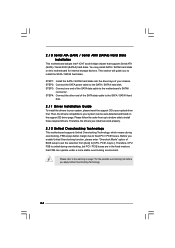
... guide you enable Untied Overclocking function, please enter "Overclock Mode" option of your system can be auto-detected and listed on the support CD driver page. STEP 2: Connect the SATA power cable to your chassis. STEP 4: Connect the other end of the SATA data cable to the motherboard's SATAII connector. Please refer to fixed PCI / PCIE buses. You may install SATA / SATAII hard disks on page 7 for the possible overclocking risk before you install can work properly. 2 . 1 2 Untied Overclocking Technology This motherboard supports Untied Overclocking Technology...
... guide you enable Untied Overclocking function, please enter "Overclock Mode" option of your system can be auto-detected and listed on the support CD driver page. STEP 2: Connect the SATA power cable to your chassis. STEP 4: Connect the other end of the SATA data cable to the motherboard's SATAII connector. Please refer to fixed PCI / PCIE buses. You may install SATA / SATAII hard disks on page 7 for the possible overclocking risk before you install can work properly. 2 . 1 2 Untied Overclocking Technology This motherboard supports Untied Overclocking Technology...
User Manual
Page 29
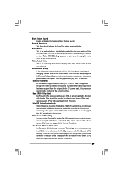
... if the current CPU does not support CPU Thermal Throttling. CPU Thermal Throttling You may select [Enabled] to enable P4 CPU internal thermal control mechanism to [Enabled], a VMM (Virtual Machine Architecture) can prevent data pages from overheated. This option will find an item Ratio CMOS Setting appears to allow you plan to allow you changing the ratio value of this motherboard. Boot Failure Guard Enable or disable the feature of...
... if the current CPU does not support CPU Thermal Throttling. CPU Thermal Throttling You may select [Enabled] to enable P4 CPU internal thermal control mechanism to [Enabled], a VMM (Virtual Machine Architecture) can prevent data pages from overheated. This option will find an item Ratio CMOS Setting appears to allow you plan to allow you changing the ratio value of this motherboard. Boot Failure Guard Enable or disable the feature of...
User Manual
Page 30
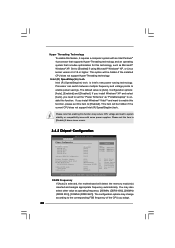
...occurs. 3.4.2 Chipset Configuration BIOS SETUP UTILITY Advanced Chipset Configuration DRAM Frequency Flexibility Option DRAM tCL DRAM tRCD DRAM tRP DRAM tRAS Advanced DRAM Configuration Primary Graphics Adapter Internal Graphics Mode Select DVMT Mode Select DVMT/FIXED Memory OnBoard HD Audio Front Panel OnBoard Lan [Auto] [Disabled] [Auto] [Auto] [Auto] [Auto] [Auto] [PCI] [Auto] [DVMT Mode] [Maximum DVMT] [Auto] [Auto] [Enabled] Options Auto 200MHz 266MHz 333MHz (DDRII400) (DDRII533) (DDRII667) +F1 F9 F10 ESC Select Screen Select Item Change Option General Help Load Defaults Save and...
...occurs. 3.4.2 Chipset Configuration BIOS SETUP UTILITY Advanced Chipset Configuration DRAM Frequency Flexibility Option DRAM tCL DRAM tRCD DRAM tRP DRAM tRAS Advanced DRAM Configuration Primary Graphics Adapter Internal Graphics Mode Select DVMT Mode Select DVMT/FIXED Memory OnBoard HD Audio Front Panel OnBoard Lan [Auto] [Disabled] [Auto] [Auto] [Auto] [Auto] [Auto] [PCI] [Auto] [DVMT Mode] [Maximum DVMT] [Auto] [Auto] [Enabled] Options Auto 200MHz 266MHz 333MHz (DDRII400) (DDRII533) (DDRII667) +F1 F9 F10 ESC Select Screen Select Item Change Option General Help Load Defaults Save and...
User Manual
Page 31
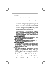
... DVMT mode, the graphics driver allocates memory as needed for the motherboard through efficient memory utilization. Flexibility Option The default value of any add-on VGA card. Configuration options: [2 DRAM Clocks], [3 DRAM Clocks], [4 DRAM Clocks], [5 DRAM Clocks], [6 DRAM Clocks] and [Auto]. The default value is [DVMT Mode]. Configuration options: [Onboard], [PCI] and [PCI Express]. the onboard VGA will be automatically disabled when you select [Enabled, 8MB] or [Enabled, 1MB], the onboard VGA will allow better tolerance for TRAS. In Fixed+DVMT mode, the graphics processor gets...
... DVMT mode, the graphics driver allocates memory as needed for the motherboard through efficient memory utilization. Flexibility Option The default value of any add-on VGA card. Configuration options: [2 DRAM Clocks], [3 DRAM Clocks], [4 DRAM Clocks], [5 DRAM Clocks], [6 DRAM Clocks] and [Auto]. The default value is [DVMT Mode]. Configuration options: [Onboard], [PCI] and [PCI Express]. the onboard VGA will be automatically disabled when you select [Enabled, 8MB] or [Enabled, 1MB], the onboard VGA will allow better tolerance for TRAS. In Fixed+DVMT mode, the graphics processor gets...
User Manual
Page 32
... PCIE clock. Configuration options: [Auto], [1.494V], [1.543V], [1.594V] and [1.643V]. If you want to enable this item is [Auto]. PCI Fix Function This allows you set to [Enabled], PCI frequency can also choose our Intelligent Energy Saver utility to enable or disable the "OnBoard Lan" feature. If this function, please set to [Disabled], PCI clock can be synchronized to [Enabled]. The default value of this to select NB core Voltage. VTT Voltage Use this feature is set DVMT Mode...
... PCIE clock. Configuration options: [Auto], [1.494V], [1.543V], [1.594V] and [1.643V]. If you want to enable this item is [Auto]. PCI Fix Function This allows you set to [Enabled], PCI frequency can also choose our Intelligent Energy Saver utility to enable or disable the "OnBoard Lan" feature. If this function, please set to [Disabled], PCI clock can be synchronized to [Enabled]. The default value of this to select NB core Voltage. VTT Voltage Use this feature is set DVMT Mode...
User Manual
Page 36
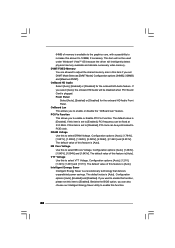
PCI Latency Timer The default value is recommended to enable or disable the S.M.A.R.T. (Self-Monitoring, Analysis, and Reporting Technology) feature. Configuration options: [Disabled], [Auto], [Enabled]. 32-Bit Data Transfer Use this item to maximize the IDE hard disk data transfer rate. 3.4.5 PCIPnP Configuration BIOS SETUP UTILITY Advanced Advanced PCI / PnP Settings PCI Latency Timer PCI IDE BusMaster [32] [Enabled] Value in units of PCI clocks for PCI device latency timer register. +F1 F9 F10 ESC Select Screen Select Item Change Option General Help Load Defaults Save...
PCI Latency Timer The default value is recommended to enable or disable the S.M.A.R.T. (Self-Monitoring, Analysis, and Reporting Technology) feature. Configuration options: [Disabled], [Auto], [Enabled]. 32-Bit Data Transfer Use this item to maximize the IDE hard disk data transfer rate. 3.4.5 PCIPnP Configuration BIOS SETUP UTILITY Advanced Advanced PCI / PnP Settings PCI Latency Timer PCI IDE BusMaster [32] [Enabled] Value in units of PCI clocks for PCI device latency timer register. +F1 F9 F10 ESC Select Screen Select Item Change Option General Help Load Defaults Save...
User Manual
Page 37
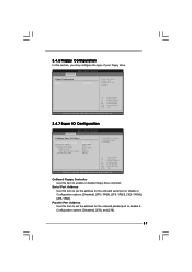
... Configuration BIOS SETUP UTILITY Advanced Configure Super IO Chipset OnBoard Floppy Controller Serial Port Address Parallel Port Address Parallel Port Mode EPP Version ECP Mode DMA Channel Parallel Port IRQ [Enabled] [3F8 / IRQ4] [378] [ECP + EPP] [1.9] [DMA3] [IRQ7] Allow BIOS to Enable or Disable Floppy Controller. +F1 F9 F10 ESC Select Screen Select Item Change Option General Help Load Defaults Save and Exit Exit v02.54 (C) Copyright 1985-2003, American Megatrends, Inc. OnBoard Floppy Controller Use this item to set the address for the onboard serial port...
... Configuration BIOS SETUP UTILITY Advanced Configure Super IO Chipset OnBoard Floppy Controller Serial Port Address Parallel Port Address Parallel Port Mode EPP Version ECP Mode DMA Channel Parallel Port IRQ [Enabled] [3F8 / IRQ4] [378] [ECP + EPP] [1.9] [DMA3] [IRQ7] Allow BIOS to Enable or Disable Floppy Controller. +F1 F9 F10 ESC Select Screen Select Item Change Option General Help Load Defaults Save and Exit Exit v02.54 (C) Copyright 1985-2003, American Megatrends, Inc. OnBoard Floppy Controller Use this item to set the address for the onboard serial port...
User Manual
Page 38
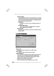
... legacy support for USB devices. Configuration options: [IRQ5] and [IRQ7]. 3.4.8 USB Configuration BIOS SETUP UTILITY Advanced USB Configuration USB Controller USB 2.0 Support Legacy USB Support [Enabled] [Enabled] [BIOS Setup Only] To enable or disable the onboard USB controllers. +F1 F9 F10 ESC Select Screen Select Item Change Option General Help Load Defaults Save and Exit Exit v02.54 (C) Copyright 1985-2005, American Megatrends, Inc. USB Controller Use this item to set to below descriptions for legacy USB. [Auto] - Please refer to [ECP+EPP], it will show the EPP version...
... legacy support for USB devices. Configuration options: [IRQ5] and [IRQ7]. 3.4.8 USB Configuration BIOS SETUP UTILITY Advanced USB Configuration USB Controller USB 2.0 Support Legacy USB Support [Enabled] [Enabled] [BIOS Setup Only] To enable or disable the onboard USB controllers. +F1 F9 F10 ESC Select Screen Select Item Change Option General Help Load Defaults Save and Exit Exit v02.54 (C) Copyright 1985-2005, American Megatrends, Inc. USB Controller Use this item to set to below descriptions for legacy USB. [Auto] - Please refer to [ECP+EPP], it will show the EPP version...
User Manual
Page 41
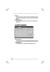
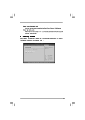
BIOS SETUP UTILITY Main Smart Advanced H/W Monitor Boot Security Exit Security Settings Supervisor Password : Not Installed User Password : Not Installed Change Supervisor Password Change User Password Install or Change the password. Select Screen Select Item Enter Change F1 General Help F9 Load Defaults F10 Save and Exit ESC Exit v02.54 (C) Copyright 1985-2005, American Megatrends, Inc. 41 Boot From Onboard LAN Use this section, you may set to enable or disable the Boot From Onboard LAN feature. For the user password, you may also clear it will automatically activate...
BIOS SETUP UTILITY Main Smart Advanced H/W Monitor Boot Security Exit Security Settings Supervisor Password : Not Installed User Password : Not Installed Change Supervisor Password Change User Password Install or Change the password. Select Screen Select Item Enter Change F1 General Help F9 Load Defaults F10 Save and Exit ESC Exit v02.54 (C) Copyright 1985-2005, American Megatrends, Inc. 41 Boot From Onboard LAN Use this section, you may set to enable or disable the Boot From Onboard LAN feature. For the user password, you may also clear it will automatically activate...

User Manual
Page 43
.... 43 Because motherboard settings and hardware options vary, use the setup procedures in the Support CD to visit ASRock's website at http://www.asrock.com; Chapter 4 Software Support 4.1 Install Operating System This motherboard supports various Microsoft® Windows® operating systems: 2000 / XP / XP 64-bit / VistaTM / VistaTM 64-bit. Please install the necessary drivers to your computer. Refer to activate the devices. 4.2.3 Utilities Menu The Utilities Menu shows the applications software that enhance...
.... 43 Because motherboard settings and hardware options vary, use the setup procedures in the Support CD to visit ASRock's website at http://www.asrock.com; Chapter 4 Software Support 4.1 Install Operating System This motherboard supports various Microsoft® Windows® operating systems: 2000 / XP / XP 64-bit / VistaTM / VistaTM 64-bit. Please install the necessary drivers to your computer. Refer to activate the devices. 4.2.3 Utilities Menu The Utilities Menu shows the applications software that enhance...
Quick Installation Guide
Page 2
... Socket 16 USB 2.0 Header (USB4_5, Blue) 3 North Bridge Controller 17 System Panel Header (PANEL1, Orange) 4 CPU Fan Connector (CPU_FAN1) 18 BIOS SPI Chip 5 2 x 240-pin DDR2 DIMM Slots 19 Chassis Fan Connector (CHA_FAN1) (Dual Channel: DDRII_1, DDRII_2; Orange) 24 PCI Express x16 Slot (PCIE2) 11 Fourth SATAII Connector (SATAII_4; Red) 26 Print Port Header (LPT1, Purple) 13 Primary SATAII Connector (SATAII_1; Yellow) 20 Floppy Connector (FLOPPY1) 6 ATX Power Connector (ATXPWR1) 21 Front Panel Audio Header 7 IDE1 Connector (IDE1, Blue) (HD_AUDIO1, Lime) 8 Clear CMOS Jumper...
... Socket 16 USB 2.0 Header (USB4_5, Blue) 3 North Bridge Controller 17 System Panel Header (PANEL1, Orange) 4 CPU Fan Connector (CPU_FAN1) 18 BIOS SPI Chip 5 2 x 240-pin DDR2 DIMM Slots 19 Chassis Fan Connector (CHA_FAN1) (Dual Channel: DDRII_1, DDRII_2; Orange) 24 PCI Express x16 Slot (PCIE2) 11 Fourth SATAII Connector (SATAII_4; Red) 26 Print Port Header (LPT1, Purple) 13 Primary SATAII Connector (SATAII_1; Yellow) 20 Floppy Connector (FLOPPY1) 6 ATX Power Connector (ATXPWR1) 21 Front Panel Audio Header 7 IDE1 Connector (IDE1, Blue) (HD_AUDIO1, Lime) 8 Clear CMOS Jumper...
Quick Installation Guide
Page 6
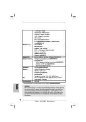
..., including adjusting the setting in header - Drivers, Utilities, AntiVirus Software (Trial Version) Unique Feature - Boot Failure Guard (B.F.G.) Hardware - It should be done at your system. Front panel audio connector - 2 x USB 2.0 headers (support 4 USB 2.0 ports) (see CAUTION 11) - Supports "Plug and Play" - CPU Quiet Fan - English 6 ASRock 945GCM-S Motherboard Hybrid Booster: - Supports jumperfree - Chassis Fan Tachometer - - 1 x Print port header - CPU/Chassis FAN connector - 24 pin ATX power connector - 4 pin 12V power connector -
..., including adjusting the setting in header - Drivers, Utilities, AntiVirus Software (Trial Version) Unique Feature - Boot Failure Guard (B.F.G.) Hardware - It should be done at your system. Front panel audio connector - 2 x USB 2.0 headers (support 4 USB 2.0 ports) (see CAUTION 11) - Supports "Plug and Play" - CPU Quiet Fan - English 6 ASRock 945GCM-S Motherboard Hybrid Booster: - Supports jumperfree - Chassis Fan Tachometer - - 1 x Print port header - CPU/Chassis FAN connector - 24 pin ATX power connector - 4 pin 12V power connector -
Quick Installation Guide
Page 7
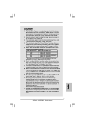
... for USB 2.0 works fine under Windows® XP, Windows® XP 64-bit, Windows® VistaTM and Windows® VistaTM 64-bit. 7. Please read the "SATAII Hard Disk Setup Guide" on page 12 for system usage under Microsoft® Windows® VistaTM 64-bit / VistaTM / XP 64-bit / XP SP1 or SP2 / 2000 SP4. 10. This motherboard supports Dual Channel Memory Technology. Before installing SATAII hard disk to SATAII connector, please read "Untied Overclocking Technology" on this motherboard...
... for USB 2.0 works fine under Windows® XP, Windows® XP 64-bit, Windows® VistaTM and Windows® VistaTM 64-bit. 7. Please read the "SATAII Hard Disk Setup Guide" on page 12 for system usage under Microsoft® Windows® VistaTM 64-bit / VistaTM / XP 64-bit / XP SP1 or SP2 / 2000 SP4. 10. This motherboard supports Dual Channel Memory Technology. Before installing SATAII hard disk to SATAII connector, please read "Untied Overclocking Technology" on this motherboard...
Quick Installation Guide
Page 19
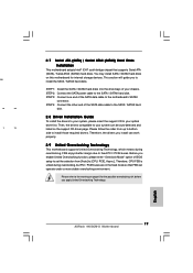
... 19 ASRock 945GCM-S Motherboard Therefore, CPU FSB is untied during overclocking, FSB enjoys better margin due to the motherboard's SATAII connector. STEP 2: Connect the SATA power cable to the warning on page 6 for internal storage devices. STEP 3: Connect one end of the SATA data cable to the SATA / SATAII hard disk. 2.8 Driver Installation Guide To install the drivers to your system can work properly. 2.9 Untied Overclocking Technology This motherboard supports Untied Overclocking Technology, which means during overclocking, but PCI / PCIE buses are in the fixed mode...
... 19 ASRock 945GCM-S Motherboard Therefore, CPU FSB is untied during overclocking, FSB enjoys better margin due to the motherboard's SATAII connector. STEP 2: Connect the SATA power cable to the warning on page 6 for internal storage devices. STEP 3: Connect one end of the SATA data cable to the SATA / SATAII hard disk. 2.8 Driver Installation Guide To install the drivers to your system can work properly. 2.9 Untied Overclocking Technology This motherboard supports Untied Overclocking Technology, which means during overclocking, but PCI / PCIE buses are in the fixed mode...
Quick Installation Guide
Page 20
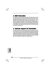
... detailed information about BIOS Setup, please refer to display the menus. 20 ASRock 945GCM-S Motherboard English EXE" from the BIN folder in the Support CD to the User Manual (PDF file) contained in your CD-ROM drive. BIOS Information The Flash Memory on the file "ASSETUP. It is a menu-driven program, which allows you start up the computer, please press during the Power-On-Self-Test (POST) to enter BIOS Setup after POST, please restart...
... detailed information about BIOS Setup, please refer to display the menus. 20 ASRock 945GCM-S Motherboard English EXE" from the BIN folder in the Support CD to the User Manual (PDF file) contained in your CD-ROM drive. BIOS Information The Flash Memory on the file "ASSETUP. It is a menu-driven program, which allows you start up the computer, please press during the Power-On-Self-Test (POST) to enter BIOS Setup after POST, please restart...


