User Manual
Page 3
... 1.3 Motherboard Layout 10 1.4 I/O Panel 11 2 Installation 12 2.1 Screw Holes 12 2.2 Pre-installation Precautions 12 2.3 CPU Installation 13 2.4 Installation of Heatsink and CPU fan 15 2.5 Installation of Memory Modules (DIMM 16 2.6 Expansion Slots (PCI and PCI Express Slots 17 2.7 Jumpers...25 3.1.1 BIOS Menu Bar 25 3.1.2 Navigation Keys 26 3.2 Main Screen 26 3.3 Smart Screen 27 3.4 Advanced Screen 28 3.4.1 CPU Configuration 28 3.4.2 Chipset Configuration 30 3.4.3 ACPI Configuration 33 3.4.4 IDE Configuration 34 3.4.5 PCIPnP Configuration 36 3.4.6 Floppy Configuration 37 ...
... 1.3 Motherboard Layout 10 1.4 I/O Panel 11 2 Installation 12 2.1 Screw Holes 12 2.2 Pre-installation Precautions 12 2.3 CPU Installation 13 2.4 Installation of Heatsink and CPU fan 15 2.5 Installation of Memory Modules (DIMM 16 2.6 Expansion Slots (PCI and PCI Express Slots 17 2.7 Jumpers...25 3.1.1 BIOS Menu Bar 25 3.1.2 Navigation Keys 26 3.2 Main Screen 26 3.3 Smart Screen 27 3.4 Advanced Screen 28 3.4.1 CPU Configuration 28 3.4.2 Chipset Configuration 30 3.4.3 ACPI Configuration 33 3.4.4 IDE Configuration 34 3.4.5 PCIPnP Configuration 36 3.4.6 Floppy Configuration 37 ...
User Manual
Page 5
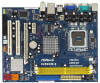
...version will be available on ASRock website as well. www.asrock.com/support/index.asp 1.1 Package Contents ASRock 945GCM-S Motherboard (Micro ATX Form Factor: 9.6-in x 7.5-in, 24.4 cm x 19.1 cm) ASRock 945GCM-S Quick Installation Guide ASRock 945GCM-S Support CD One 80-conductor... Ultra ATA 66/100 IDE Ribbon Cable (Optional) One Serial ATA (SATA) Data Cable (Optional) One Serial ATA (SATA) HDD Power Cable (Optional) One I/O Panel Shield 5 You may find the latest VGA cards and CPU support lists on ASRock...
...version will be available on ASRock website as well. www.asrock.com/support/index.asp 1.1 Package Contents ASRock 945GCM-S Motherboard (Micro ATX Form Factor: 9.6-in x 7.5-in, 24.4 cm x 19.1 cm) ASRock 945GCM-S Quick Installation Guide ASRock 945GCM-S Support CD One 80-conductor... Ultra ATA 66/100 IDE Ribbon Cable (Optional) One Serial ATA (SATA) Data Cable (Optional) One Serial ATA (SATA) HDD Power Cable (Optional) One I/O Panel Shield 5 You may find the latest VGA cards and CPU support lists on ASRock...
User Manual
Page 6
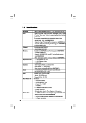
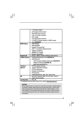
...: Intel® ICH7 - Max. Realtek PCIE x1 LAN 8102EL - Supports Wake-On-LAN I /O Connector - Northbridge: Intel® 945GC - Max. 1.2 Specifications Platform CPU Chipset Memory Expansion Slot Graphics Audio LAN Rear Panel I /O Panel - 1 x PS/2 Mouse Port - 1 x PS/2 Keyboard Port - 1 x Serial Port: COM1... - 1 x VGA Port - 4 x Ready-to-Use USB 2.0 Ports - 1 x RJ-45 LAN Port - Supports EM64T CPU - Dual Channel DDR2 Memory Technology (see CAUTION 2) - Intel® Graphics Media Accelerator 950 - LGA 775 for RAID and "Hot Plug" functions) (see CAUTION 1)...
...: Intel® ICH7 - Max. Realtek PCIE x1 LAN 8102EL - Supports Wake-On-LAN I /O Connector - Northbridge: Intel® 945GC - Max. 1.2 Specifications Platform CPU Chipset Memory Expansion Slot Graphics Audio LAN Rear Panel I /O Panel - 1 x PS/2 Mouse Port - 1 x PS/2 Keyboard Port - 1 x Serial Port: COM1... - 1 x VGA Port - 4 x Ready-to-Use USB 2.0 Ports - 1 x RJ-45 LAN Port - Supports EM64T CPU - Dual Channel DDR2 Memory Technology (see CAUTION 2) - Intel® Graphics Media Accelerator 950 - LGA 775 for RAID and "Hot Plug" functions) (see CAUTION 1)...
User Manual
Page 7
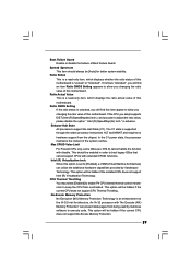
...ports) (see CAUTION 11) - - 1 x Print port header - Supports Smart BIOS Support CD - Intelligent Energy Saver (see CAUTION 12) - CPU Temperature Sensing Monitor - AMI Legal BIOS - CD in the BIOS, applying Untied Overclocking Technology, or using the thirdparty overclocking tools. ACPI 1.1 Compliance Wake... Drivers, Utilities, AntiVirus Software (Trial Version) Unique Feature - ASRock U-COP (see CAUTION 10) - FCC, CE * For detailed product information, please visit our website: http://www.asrock.com WARNING Please realize that there is a certain risk involved with...
...ports) (see CAUTION 11) - - 1 x Print port header - Supports Smart BIOS Support CD - Intelligent Energy Saver (see CAUTION 12) - CPU Temperature Sensing Monitor - AMI Legal BIOS - CD in the BIOS, applying Untied Overclocking Technology, or using the thirdparty overclocking tools. ACPI 1.1 Compliance Wake... Drivers, Utilities, AntiVirus Software (Trial Version) Unique Feature - ASRock U-COP (see CAUTION 10) - FCC, CE * For detailed product information, please visit our website: http://www.asrock.com WARNING Please realize that there is a certain risk involved with...
User Manual
Page 8
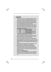
...maximum shared memory size is defined by the chipset vendor and is a revolutionary technology that delivers unparalleled power savings. ASRock website: http://www.asrock.com 11. About the setting of memory modules on this motherboard offers stepless control, it is able to provide ...software design, Intelligent Energy Saver is subject to 115MHz. Under this situation, PCIE frequency will also be less than the recommended CPU bus frequencies may be overclocked to change. Please check the table below for proper jumper settings. 2. Although this motherboard, it...
...maximum shared memory size is defined by the chipset vendor and is a revolutionary technology that delivers unparalleled power savings. ASRock website: http://www.asrock.com 11. About the setting of memory modules on this motherboard offers stepless control, it is able to provide ...software design, Intelligent Energy Saver is subject to 115MHz. Under this situation, PCIE frequency will also be less than the recommended CPU bus frequencies may be overclocked to change. Please check the table below for proper jumper settings. 2. Although this motherboard, it...

User Manual
Page 9
To improve heat dissipation, remember to spray thermal grease between the CPU and the heatsink when you resume the system, please check if the CPU fan on the motherboard functions properly and unplug the power cord, then plug it back again. Before you install the PC system. 9 While CPU overheat is detected, the system will automatically shutdown. 12.
To improve heat dissipation, remember to spray thermal grease between the CPU and the heatsink when you resume the system, please check if the CPU fan on the motherboard functions properly and unplug the power cord, then plug it back again. Before you install the PC system. 9 While CPU overheat is detected, the system will automatically shutdown. 12.
User Manual
Page 10
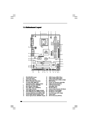
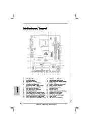
...PCIE2 PCI EXPRESS PCI1 IDE1 RoHS Intel ICH7 SATAII_3 SATAII_1 PCI2 CHA_FAN1 4Mb BIOS PANEL 1 PLED PWRBTN 1 HDLED RESET USB4_5 1 USB6_7 1 SPEAKER1 1 945GCM-S SATAII_2 SATAII_4 7 8 9 10 11 21 20 19 18 17 16 15 14 13 12 1 PS2_USB_PWR1 Jumper 15 USB 2.0 Header (USB6_7, Blue) 2... 775-Pin CPU Socket 16 USB 2.0 Header (USB4_5, Blue) 3 North Bridge Controller 17 System Panel Header (PANEL1, Orange) 4 CPU Fan Connector (CPU_FAN1) 18 BIOS SPI Chip 5 2 x 240-pin DDR2 DIMM Slots 19 Chassis Fan ...
...PCIE2 PCI EXPRESS PCI1 IDE1 RoHS Intel ICH7 SATAII_3 SATAII_1 PCI2 CHA_FAN1 4Mb BIOS PANEL 1 PLED PWRBTN 1 HDLED RESET USB4_5 1 USB6_7 1 SPEAKER1 1 945GCM-S SATAII_2 SATAII_4 7 8 9 10 11 21 20 19 18 17 16 15 14 13 12 1 PS2_USB_PWR1 Jumper 15 USB 2.0 Header (USB6_7, Blue) 2... 775-Pin CPU Socket 16 USB 2.0 Header (USB4_5, Blue) 3 North Bridge Controller 17 System Panel Header (PANEL1, Orange) 4 CPU Fan Connector (CPU_FAN1) 18 BIOS SPI Chip 5 2 x 240-pin DDR2 DIMM Slots 19 Chassis Fan ...
User Manual
Page 13
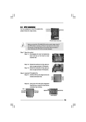
... key notch orientation key notch Pin1 alignment key alignment key 775-LAND CPU 775-Pin Socket 13 black line black line Step 2-2. Orient the CPU with black lines. 2.3 CPU Installation For the installation of Intel 775-LAND CPU, please follow the steps below. 775-Pin Socket Overview Before you ...insert the 775-LAND CPU into the socket if above situation is any bent pin...
... key notch orientation key notch Pin1 alignment key alignment key 775-LAND CPU 775-Pin Socket 13 black line black line Step 2-2. Orient the CPU with black lines. 2.3 CPU Installation For the installation of Intel 775-LAND CPU, please follow the steps below. 775-Pin Socket Overview Before you ...insert the 775-LAND CPU into the socket if above situation is any bent pin...

User Manual
Page 14
Step 2-3. Step 2-4. It is within the socket and properly mated to match the two orientation key notches of the CPU with load plate tab under retention tab of load lever. 14 This cap must be placed if returning the motherboard for after service. Step 4-2. Secure ... the socket while pressing on load plate, engage the load lever. Close the socket: Step 4-1. Rotate the load plate onto the IHS. Verify that the CPU is recommended to use the cap tab to assist in removal. 1. Step 4-3. Step 4. While pressing down lightly on center of the socket. Carefully place the...
Step 2-3. Step 2-4. It is within the socket and properly mated to match the two orientation key notches of the CPU with load plate tab under retention tab of load lever. 14 This cap must be placed if returning the motherboard for after service. Step 4-2. Secure ... the socket while pressing on load plate, engage the load lever. Close the socket: Step 4-1. Rotate the load plate onto the IHS. Verify that the CPU is recommended to use the cap tab to assist in removal. 1. Step 4-3. Step 4. While pressing down lightly on center of the socket. Carefully place the...

User Manual
Page 15
... 4). Apply thermal interface material onto center of heatsink and cooling fan compliant with 775-Pin socket that the CPU and the heatsink are oriented on side closest to the CPU fan connector on the socket surface. Step 4. Ensure fan cables are securely fastened and in good contact with...fan operation or contact other . If you need to spray thermal interface material between the CPU and the heatsink to improve heat dissipation. Step 3. Step 6. Ensure that supports Intel 775-LAND CPU. Secure excess cable with tie-wrap to ensure cable does not interfere with each other ...
... 4). Apply thermal interface material onto center of heatsink and cooling fan compliant with 775-Pin socket that the CPU and the heatsink are oriented on side closest to the CPU fan connector on the socket surface. Step 4. Ensure fan cables are securely fastened and in good contact with...fan operation or contact other . If you need to spray thermal interface material between the CPU and the heatsink to improve heat dissipation. Step 3. Step 6. Ensure that supports Intel 775-LAND CPU. Secure excess cable with tie-wrap to ensure cable does not interfere with each other ...

User Manual
Page 18
... want to clear the data in CMOS includes system setup information such as system password, date, time, and system setup parameters. Otherwise, the CPU may not work properly on pins, the jumper is "Open". 2.7 Jumpers Setup The illustration shows how jumpers are "Short" when jumper cap ...no jumper cap is placed on this motherboard, you need to enable +5VSB (standby) for 5 seconds. Cel400, E1000, E2000, E4000, E5000, E6000 series CPU) to short 2 pins on this motherboard. After waiting for 15 seconds, use a jumper cap to FSB1066 on CLRCMOS1 for PS/2 +5V +5VSB or USB...
... want to clear the data in CMOS includes system setup information such as system password, date, time, and system setup parameters. Otherwise, the CPU may not work properly on pins, the jumper is "Open". 2.7 Jumpers Setup The illustration shows how jumpers are "Short" when jumper cap ...no jumper cap is placed on this motherboard, you need to enable +5VSB (standby) for 5 seconds. Cel400, E1000, E2000, E4000, E5000, E6000 series CPU) to short 2 pins on this motherboard. After waiting for 15 seconds, use a jumper cap to FSB1066 on CLRCMOS1 for PS/2 +5V +5VSB or USB...
User Manual
Page 21
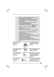
E. G. If you want to enter Realtek HD Audio Manager. CPU Fan Connector (4-pin CPU_FAN1) (see p.10 No. 19) PLED+ PLEDPWRBTN# GND 1 DUMMY RESET# GND HDLEDHDLED+ 1 SPEAKER DUMMY DUMMY +5V This header accommodates several system...pin PANEL1) (see p.10 No. 17) Chassis Speaker Header (4-pin SPEAKER 1) (see p.10 No. 14) Chassis Fan Connector (3-pin CHA_FAN1) (see p.10 No. 4) Please connect a CPU fan cable 1 GND 2 +12V to this header. Please connect the chassis speaker to [Enabled]. Enter Advanced Settings, and then select Chipset Configuration. For Windows®...
E. G. If you want to enter Realtek HD Audio Manager. CPU Fan Connector (4-pin CPU_FAN1) (see p.10 No. 19) PLED+ PLEDPWRBTN# GND 1 DUMMY RESET# GND HDLEDHDLED+ 1 SPEAKER DUMMY DUMMY +5V This header accommodates several system...pin PANEL1) (see p.10 No. 17) Chassis Speaker Header (4-pin SPEAKER 1) (see p.10 No. 14) Chassis Fan Connector (3-pin CHA_FAN1) (see p.10 No. 4) Please connect a CPU fan cable 1 GND 2 +12V to this header. Please connect the chassis speaker to [Enabled]. Enter Advanced Settings, and then select Chipset Configuration. For Windows®...

User Manual
Page 22
... this connector. 1 13 Though this motherboard provides 24-pin ATX power connector, 12 24 it can work if you plan to connect the 3-Pin CPU fan to the CPU fan connector on this motherboard, please connect it can provides sufficient power. Pin 1-3 Connected 3-Pin Fan Installation ATX Power Connector (24-pin ATXPWR1... is necessary to connect a power supply with ATX 12V plug to this connector so that it to power up. 22 Though this motherboard provides 4-Pin CPU fan (Quiet Fan) support, the 3-Pin CPU fan still can still work successfully even without the fan speed control function.
... this connector. 1 13 Though this motherboard provides 24-pin ATX power connector, 12 24 it can work if you plan to connect the 3-Pin CPU fan to the CPU fan connector on this motherboard, please connect it can provides sufficient power. Pin 1-3 Connected 3-Pin Fan Installation ATX Power Connector (24-pin ATXPWR1... is necessary to connect a power supply with ATX 12V plug to this connector so that it to power up. 22 Though this motherboard provides 4-Pin CPU fan (Quiet Fan) support, the 3-Pin CPU fan still can still work successfully even without the fan speed control function.
User Manual
Page 24
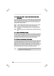
... page 7 for internal storage devices. Please follow the order from [Auto] to install the SATA / SATAII hard disks. Therefore, the drivers you to [CPU, PCIE, Async.]. Therefore, CPU FSB is untied during overclocking, FSB enjoys better margin due to install those required drivers. Then, the drivers compatible to the SATA / SATAII hard...
... page 7 for internal storage devices. Please follow the order from [Auto] to install the SATA / SATAII hard disks. Therefore, the drivers you to [CPU, PCIE, Async.]. Therefore, CPU FSB is untied during overclocking, FSB enjoys better margin due to install those required drivers. Then, the drivers compatible to the SATA / SATAII hard...
User Manual
Page 26
... UTILITY Main Smart Advanced H/W Monitor Boot Security Exit System Overview System Time System Date [14:00:09] [Thu 07/31/2008] BIOS Version : 945GCM-S P1.00 Processor Type : Intel (R) CPU 3.40 GHz (64bit) Processor Speed : 3400 MHz Microcode Update : F34/17 Cache Size : 1024KB Total Memory DDRII1 DDRII2 : 512MB with 8MB shared...
... UTILITY Main Smart Advanced H/W Monitor Boot Security Exit System Overview System Time System Date [14:00:09] [Thu 07/31/2008] BIOS Version : 945GCM-S P1.00 Processor Type : Intel (R) CPU 3.40 GHz (64bit) Processor Speed : 3400 MHz Microcode Update : F34/17 Cache Size : 1024KB Total Memory DDRII1 DDRII2 : 512MB with 8MB shared...
User Manual
Page 28
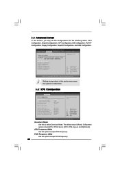
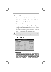
... Mode. 3.4 Advanced Screen In this section, you may cause the system to malfunction. 3.4.1 CPU Configuration BIOS SETUP UTILITY Advanced CPU Configuration Overclock Mode CPU Frequency (MHz) PCIE Frequency (MHz) Boot Failure Guard Spread Spectrum Ratio Actual Value Enhance Halt...Monitor Boot Security Exit Advanced Settings WARNING : Setting wrong values in this section may set the configurations for CPU CPU Configuration Chipset Configuration ACPI Configuration IDE Configuration PCIPnP Configuration Floppy Configuration SuperIO Configuration USB Configuration Select Screen Select Item...
... Mode. 3.4 Advanced Screen In this section, you may cause the system to malfunction. 3.4.1 CPU Configuration BIOS SETUP UTILITY Advanced CPU Configuration Overclock Mode CPU Frequency (MHz) PCIE Frequency (MHz) Boot Failure Guard Spread Spectrum Ratio Actual Value Enhance Halt...Monitor Boot Security Exit Advanced Settings WARNING : Setting wrong values in this section may set the configurations for CPU CPU Configuration Chipset Configuration ACPI Configuration IDE Configuration PCIPnP Configuration Floppy Configuration SuperIO Configuration USB Configuration Select Screen Select Item...
User Manual
Page 29
...OSes that cannot support CPUs with extended CPUID functions. in order to the IA-32 Intel Architecture. Max CPUID Value Limit For Prescott CPU only, some OSes (ex. No-Excute Memory Protection No-Execution (NX) Memory Protection Technology is supported through the native processor instructions... HLT and MWAIT and requires no hardware support from overheated. Intel (R) Virtualization tech. This option will be hidden if the current CPU does not support No-Excute Memory Protection. 29 Boot Failure Guard Enable or disable the feature of the system caches. Ratio Status This...
...OSes that cannot support CPUs with extended CPUID functions. in order to the IA-32 Intel Architecture. Max CPUID Value Limit For Prescott CPU only, some OSes (ex. No-Excute Memory Protection No-Execution (NX) Memory Protection Technology is supported through the native processor instructions... HLT and MWAIT and requires no hardware support from overheated. Intel (R) Virtualization tech. This option will be hidden if the current CPU does not support No-Excute Memory Protection. 29 Boot Failure Guard Enable or disable the feature of the system caches. Ratio Status This...
User Manual
Page 30
..."Portable/Laptop" to [Enabled]. Intel (R) SpeedStep(tm) tech. The configuration options may change according to the corresponding FSB frequency of the CPU you install Windows® VistaTM and want to enable this function, please set this item to enable this function. If you install Windows&#...system that enabling this function may also select other value as Microsoft® Windows® XP. This option will be hidden if the current CPU does not support Intel (R) SpeedStep(tm) tech.. is [Auto]. Intel (R) SpeedStep(tm) tech. Please note that includes optimization for this...
..."Portable/Laptop" to [Enabled]. Intel (R) SpeedStep(tm) tech. The configuration options may change according to the corresponding FSB frequency of the CPU you install Windows® VistaTM and want to enable this function, please set this item to enable this function. If you install Windows&#...system that enabling this function may also select other value as Microsoft® Windows® XP. This option will be hidden if the current CPU does not support Intel (R) SpeedStep(tm) tech.. is [Auto]. Intel (R) SpeedStep(tm) tech. Please note that includes optimization for this...
User Manual
Page 39
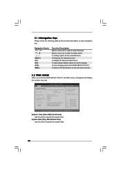
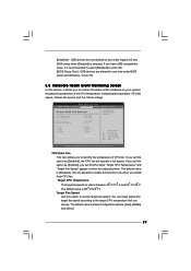
...Save and Exit Exit v02.54 (C) Copyright 1985-2003, American Megatrends, Inc. You can freely adjust the target fan speed according to the target CPU temperature that you to use under BIOS setup and Windows / Linux OS. 3.5 Hardware Health Event Monitoring Screen In this section, it is recommended to... select [Disabled] to enable this option as [Enabled], you will find the items "Target CPU Temperature" and "Target Fan Speed" appear to allow you to set this function only when you set the target fan speed. If you install ...
...Save and Exit Exit v02.54 (C) Copyright 1985-2003, American Megatrends, Inc. You can freely adjust the target fan speed according to the target CPU temperature that you to use under BIOS setup and Windows / Linux OS. 3.5 Hardware Health Event Monitoring Screen In this section, it is recommended to... select [Disabled] to enable this option as [Enabled], you will find the items "Target CPU Temperature" and "Target Fan Speed" appear to allow you to set this function only when you set the target fan speed. If you install ...
Quick Installation Guide
Page 2
...Third SATAII Connector (SATAII_3; Red) 27 OC 800 Jumper 14 Chassis Speaker Header (SPEAKER 1, Purple) 28 ATX 12V Connector (ATX12V1) 2 ASRock 945GCM-S Motherboard Red) 26 Print Port Header (LPT1, Purple) 13 Primary SATAII Connector (SATAII_1; Motherboard Layout English 1 PS2_USB_PWR1 Jumper 15 USB 2.0... Header (USB6_7, Blue) 2 775-Pin CPU Socket 16 USB 2.0 Header (USB4_5, Blue) 3 North Bridge Controller 17 System Panel Header (PANEL1, Orange) 4 CPU Fan Connector (CPU_FAN1) 18 BIOS SPI Chip 5 2 x 240-pin DDR2 DIMM Slots...
...Third SATAII Connector (SATAII_3; Red) 27 OC 800 Jumper 14 Chassis Speaker Header (SPEAKER 1, Purple) 28 ATX 12V Connector (ATX12V1) 2 ASRock 945GCM-S Motherboard Red) 26 Print Port Header (LPT1, Purple) 13 Primary SATAII Connector (SATAII_1; Motherboard Layout English 1 PS2_USB_PWR1 Jumper 15 USB 2.0... Header (USB6_7, Blue) 2 775-Pin CPU Socket 16 USB 2.0 Header (USB4_5, Blue) 3 North Bridge Controller 17 System Panel Header (PANEL1, Orange) 4 CPU Fan Connector (CPU_FAN1) 18 BIOS SPI Chip 5 2 x 240-pin DDR2 DIMM Slots...


