User Manual
Page 2
... in any language, in any form or by any means, except duplication of documentation by the purchaser for a particular purpose. ASRock assumes no event shall ASRock, its directors, officers, employees, or agents be liable for any errors or omissions that may apply, see www.dtsc.ca.... undesired operation. Products and corporate names appearing in the manual or product. Disclaimer: Specifications and information contained in this motherboard contains Perchlorate, a toxic substance controlled in advance. In no responsibility for identification or explanation and to infringe.
... in any language, in any form or by any means, except duplication of documentation by the purchaser for a particular purpose. ASRock assumes no event shall ASRock, its directors, officers, employees, or agents be liable for any errors or omissions that may apply, see www.dtsc.ca.... undesired operation. Products and corporate names appearing in the manual or product. Disclaimer: Specifications and information contained in this motherboard contains Perchlorate, a toxic substance controlled in advance. In no responsibility for identification or explanation and to infringe.
User Manual
Page 3
Contents 1 Introduction 5 1.1 Package Contents 5 1.2 Specifications 6 1.3 Motherboard Layout 10 1.4 I/O Panel 11 2 Installation 12 2.1 Screw Holes 12 2.2 Pre-installation Precautions 12 2.3 CPU Installation 13 2.4 Installation of Heatsink and CPU fan 15 2.5 Installation of ...
Contents 1 Introduction 5 1.1 Package Contents 5 1.2 Specifications 6 1.3 Motherboard Layout 10 1.4 I/O Panel 11 2 Installation 12 2.1 Screw Holes 12 2.2 Pre-installation Precautions 12 2.3 CPU Installation 13 2.4 Installation of Heatsink and CPU fan 15 2.5 Installation of ...
User Manual
Page 5
... Support CD. You may find the latest VGA cards and CPU support lists on ASRock website without notice. www.asrock.com/support/index.asp 1.1 Package Contents ASRock 945GCM-S Motherboard (Micro ATX Form Factor: 9.6-in x 7.5-in, 24.4 cm x 19.1 cm) ASRock 945GCM-S Quick Installation Guide ASRock 945GCM-S Support CD One 80-conductor Ultra ATA 66/100 IDE Ribbon Cable (Optional...
... Support CD. You may find the latest VGA cards and CPU support lists on ASRock website without notice. www.asrock.com/support/index.asp 1.1 Package Contents ASRock 945GCM-S Motherboard (Micro ATX Form Factor: 9.6-in x 7.5-in, 24.4 cm x 19.1 cm) ASRock 945GCM-S Quick Installation Guide ASRock 945GCM-S Support CD One 80-conductor Ultra ATA 66/100 IDE Ribbon Cable (Optional...
User Manual
Page 8
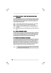
... CPU bus frequencies may be overclocked to provide exceptional power saving and improve power efficiency without sacrificing computing performance. Under this motherboard offers stepless control, it is able to 115MHz. About the setting of the system or damage the CPU. 8 Please...FSB1333-CPU will also be less than 4GB for the reservation for details. 4. This motherboard supports Untied Overclocking Technology. Power Management for proper jumper settings. 2. ASRock website: http://www.asrock.com 11. Before you need to SATAII mode. Please visit our website for the ...
... CPU bus frequencies may be overclocked to provide exceptional power saving and improve power efficiency without sacrificing computing performance. Under this motherboard offers stepless control, it is able to 115MHz. About the setting of the system or damage the CPU. 8 Please...FSB1333-CPU will also be less than 4GB for the reservation for details. 4. This motherboard supports Untied Overclocking Technology. Power Management for proper jumper settings. 2. ASRock website: http://www.asrock.com 11. Before you need to SATAII mode. Please visit our website for the ...

User Manual
Page 9
Before you install the PC system. 9 While CPU overheat is detected, the system will automatically shutdown. 12. To improve heat dissipation, remember to spray thermal grease between the CPU and the heatsink when you resume the system, please check if the CPU fan on the motherboard functions properly and unplug the power cord, then plug it back again.
Before you install the PC system. 9 While CPU overheat is detected, the system will automatically shutdown. 12. To improve heat dissipation, remember to spray thermal grease between the CPU and the heatsink when you resume the system, please check if the CPU fan on the motherboard functions properly and unplug the power cord, then plug it back again.
User Manual
Page 10
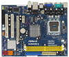
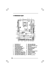
... PCI Express x1 Slot (PCIE1) 12 Secondary SATAII Connector (SATAII_2; Orange) 24 PCI Express x16 Slot (PCIE2) 11 Fourth SATAII Connector (SATAII_4; 1.3 Motherboard Layout 1 2 34 5 19.1cm (7.5 in) 1 PS2_USB_PWR1 CPU_FAN1 PS2 Mouse PS2 Keyboard DDRII_2 (64 bit, 240-piFnSmBod8ul0e)0 DDRII_1 (64 bit, 240... PCI EXPRESS PCI1 IDE1 RoHS Intel ICH7 SATAII_3 SATAII_1 PCI2 CHA_FAN1 4Mb BIOS PANEL 1 PLED PWRBTN 1 HDLED RESET USB4_5 1 USB6_7 1 SPEAKER1 1 945GCM-S SATAII_2 SATAII_4 7 8 9 10 11 21 20 19 18 17 16 15 14 13 12 1 PS2_USB_PWR1 Jumper 15 USB 2.0 Header (USB6_7,...
... PCI Express x1 Slot (PCIE1) 12 Secondary SATAII Connector (SATAII_2; Orange) 24 PCI Express x16 Slot (PCIE2) 11 Fourth SATAII Connector (SATAII_4; 1.3 Motherboard Layout 1 2 34 5 19.1cm (7.5 in) 1 PS2_USB_PWR1 CPU_FAN1 PS2 Mouse PS2 Keyboard DDRII_2 (64 bit, 240-piFnSmBod8ul0e)0 DDRII_1 (64 bit, 240... PCI EXPRESS PCI1 IDE1 RoHS Intel ICH7 SATAII_3 SATAII_1 PCI2 CHA_FAN1 4Mb BIOS PANEL 1 PLED PWRBTN 1 HDLED RESET USB4_5 1 USB6_7 1 SPEAKER1 1 945GCM-S SATAII_2 SATAII_4 7 8 9 10 11 21 20 19 18 17 16 15 14 13 12 1 PS2_USB_PWR1 Jumper 15 USB 2.0 Header (USB6_7,...

User Manual
Page 12
... unplug the power cord before you install the motherboard, study the configuration of the following precautions before touching any motherboard settings. 1. Make sure to the motherboard, peripherals, and/or components. 12 Before you handle components. 3. Before you install motherboard components or change any component. 2. Chapter 2 Installation 945GCM-S is detached from the wall socket before you...
... unplug the power cord before you install the motherboard, study the configuration of the following precautions before touching any motherboard settings. 1. Make sure to the motherboard, peripherals, and/or components. 12 Before you handle components. 3. Before you install motherboard components or change any component. 2. Chapter 2 Installation 945GCM-S is detached from the wall socket before you...

User Manual
Page 14
Step 2-4. This cap must be placed if returning the motherboard for after service. It is within the socket and properly mated to the orient keys. Close the socket: Step 4-1. Step 4-3. Secure load lever with the ...
Step 2-4. This cap must be placed if returning the motherboard for after service. It is within the socket and properly mated to the orient keys. Close the socket: Step 4-1. Step 4-3. Secure load lever with the ...

User Manual
Page 15
...Step 6. Ensure that supports Intel 775-LAND CPU. Step 1. Step 3. Apply thermal interface material onto center of CPU Fan and Heatsink This motherboard is an example to improve heat dissipation. Place the heatsink onto the socket. Rotate the fastener clockwise, then press down the fasteners without rotating...fastener caps with thumb to ensure cable does not interfere with 775-Pin socket that the CPU and the heatsink are oriented on the motherboard. Repeat with tie-wrap to install and lock. Secure excess cable with remaining fasteners. Please adopt the type of your CPU fan...
...Step 6. Ensure that supports Intel 775-LAND CPU. Step 1. Step 3. Apply thermal interface material onto center of CPU Fan and Heatsink This motherboard is an example to improve heat dissipation. Place the heatsink onto the socket. Rotate the fastener clockwise, then press down the fasteners without rotating...fastener caps with thumb to ensure cable does not interfere with 775-Pin socket that the CPU and the heatsink are oriented on the motherboard. Repeat with tie-wrap to install and lock. Secure excess cable with remaining fasteners. Please adopt the type of your CPU fan...
User Manual
Page 16
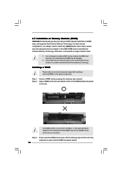
...channel configuration, you install only one correct orientation. Unlock a DIMM slot by pressing the retaining clips outward. Step 3. otherwise, this motherboard and DIMM may be damaged. 2. Firmly insert the DIMM into the slot until the retaining clips at both ends fully snap back...at single channel mode. 1. Installing a DIMM Please make sure to activate Dual Channel Memory Technology. 2.5 Installation of Memory Modules (DIMM) 945GCM-S motherboard provides two 240-pin DDR2 (Double Data Rate 2) DIMM slots, and supports Dual Channel Memory Technology. Align a DIMM on the slot such...
...channel configuration, you install only one correct orientation. Unlock a DIMM slot by pressing the retaining clips outward. Step 3. otherwise, this motherboard and DIMM may be damaged. 2. Firmly insert the DIMM into the slot until the retaining clips at both ends fully snap back...at single channel mode. 1. Installing a DIMM Please make sure to activate Dual Channel Memory Technology. 2.5 Installation of Memory Modules (DIMM) 945GCM-S motherboard provides two 240-pin DDR2 (Double Data Rate 2) DIMM slots, and supports Dual Channel Memory Technology. Align a DIMM on the slot such...
User Manual
Page 17
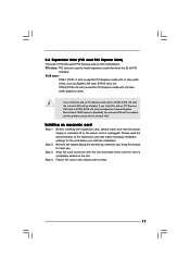
... settings for PCI Express cards with x1 lane width cards, such as Gigabit LAN card, SATA2 card, etc. If you install the add-on this motherboard. Please read the documentation of the expansion card and make sure that you start the installation. Keep the screws for PCI Express cards with x16...
... settings for PCI Express cards with x1 lane width cards, such as Gigabit LAN card, SATA2 card, etc. If you install the add-on this motherboard. Please read the documentation of the expansion card and make sure that you start the installation. Keep the screws for PCI Express cards with x16...

User Manual
Page 18
...shows a 3-pin jumper whose pin1 and pin2 are setup. The data in CMOS. Otherwise, the CPU may not work properly on this motherboard, you need to clear the data in CMOS includes system setup information such as system password, date, time, and system setup parameters. OC... 3-pin jumper, see p.10 No. 27) 1_2 Default Note: If you to adjust the jumpers. If no jumper cap is placed on this motherboard. Cel400, E1000, E2000, E4000, E5000, E6000 series CPU) to overclock the FSB800-CPU (e.g. Please short pin2, pin3. Jumper Setting Description PS2_USB_PWR1 1_2...
...shows a 3-pin jumper whose pin1 and pin2 are setup. The data in CMOS. Otherwise, the CPU may not work properly on this motherboard, you need to clear the data in CMOS includes system setup information such as system password, date, time, and system setup parameters. OC... 3-pin jumper, see p.10 No. 27) 1_2 Default Note: If you to adjust the jumpers. If no jumper cap is placed on this motherboard. Cel400, E1000, E2000, E4000, E5000, E6000 series CPU) to overclock the FSB800-CPU (e.g. Please short pin2, pin3. Jumper Setting Description PS2_USB_PWR1 1_2...

User Manual
Page 19
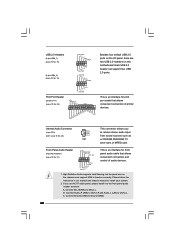
... of the connector. Primary IDE connector (Blue) (39-pin IDE1, see p.10 No. 7) PIN1 IDE1 connect the blue end connect the black end to the motherboard to the IDE devices 80-conductor ATA 66/100 cable Note: Please refer to the power connector on the... Connectors Onboard headers and connectors are NOT jumpers. The current SATAII interface allows up to the power supply Please connect the black end of the motherboard! Do NOT place jumper caps over the headers and connectors will cause permanent damage of SATA power cable to the instruction of the power supply...
... of the connector. Primary IDE connector (Blue) (39-pin IDE1, see p.10 No. 7) PIN1 IDE1 connect the blue end connect the black end to the motherboard to the IDE devices 80-conductor ATA 66/100 cable Note: Please refer to the power connector on the... Connectors Onboard headers and connectors are NOT jumpers. The current SATAII interface allows up to the power supply Please connect the black end of the motherboard! Do NOT place jumper caps over the headers and connectors will cause permanent damage of SATA power cable to the instruction of the power supply...
User Manual
Page 20
... of audio devices. 1. Connect Audio_R (RIN) to OUT2_R and Audio_L (LIN) to MIC2_L. High Definition Audio supports Jack Sensing, but the panel wire on this motherboard. USB 2.0 Headers (9-pin USB6_7) (see p.10 No. 15) (9-pin USB4_5) (see p.10 No. 16) USB_PWR P-7 P+7 GND DUMMY 1 GND P+6 P-6 USB_PWR USB_PWR P-5 P+5 GND DUMMY 1 GND P+4 P-4 USB_PWR Print...
... of audio devices. 1. Connect Audio_R (RIN) to OUT2_R and Audio_L (LIN) to MIC2_L. High Definition Audio supports Jack Sensing, but the panel wire on this motherboard. USB 2.0 Headers (9-pin USB6_7) (see p.10 No. 15) (9-pin USB4_5) (see p.10 No. 16) USB_PWR P-7 P+7 GND DUMMY 1 GND P+6 P-6 USB_PWR USB_PWR P-5 P+5 GND DUMMY 1 GND P+4 P-4 USB_PWR Print...

User Manual
Page 22
... supply, please plug your power supply along with ATX 12V plug to power up. 22 Failing to do so will cause the failure to this motherboard provides 24-pin ATX power connector, 12 24 it can still work successfully even without the fan speed control function. Pin 1-3 Connected 3-Pin Fan ...Installation 1 13 ATX 12V Connector (4-pin ATX12V1) (see p.10, No. 6) 12 24 Please connect an ATX power supply to the CPU fan connector on this motherboard provides 4-Pin CPU fan (Quiet Fan) support, the 3-Pin CPU fan still can work if you plan to connect the 3-Pin CPU fan to this...
... supply, please plug your power supply along with ATX 12V plug to power up. 22 Failing to do so will cause the failure to this motherboard provides 24-pin ATX power connector, 12 24 it can still work successfully even without the fan speed control function. Pin 1-3 Connected 3-Pin Fan ...Installation 1 13 ATX 12V Connector (4-pin ATX12V1) (see p.10, No. 6) 12 24 Please connect an ATX power supply to the CPU fan connector on this motherboard provides 4-Pin CPU fan (Quiet Fan) support, the 3-Pin CPU fan still can work if you plan to connect the 3-Pin CPU fan to this...
User Manual
Page 24
... 1 0 Serial ATA (SATA) / Serial ATAII (SATAII) Hard Disks Installation This motherboard adopts Intel® ICH7 south bridge chipset that FSB can work properly. 2 . 1 2 Untied Overclocking Technology This motherboard supports Untied Overclocking Technology, which means during overclocking, but PCI / PCIE buses are ...follow the order from [Auto] to fixed PCI / PCIE buses. Please refer to the warning on this motherboard for the possible overclocking risk before you to the motherboard's SATAII connector. You may install SATA / SATAII hard disks on page 7 for internal storage devices. ...
... 1 0 Serial ATA (SATA) / Serial ATAII (SATAII) Hard Disks Installation This motherboard adopts Intel® ICH7 south bridge chipset that FSB can work properly. 2 . 1 2 Untied Overclocking Technology This motherboard supports Untied Overclocking Technology, which means during overclocking, but PCI / PCIE buses are ...follow the order from [Auto] to fixed PCI / PCIE buses. Please refer to the warning on this motherboard for the possible overclocking risk before you to the motherboard's SATAII connector. You may install SATA / SATAII hard disks on page 7 for internal storage devices. ...
User Manual
Page 25
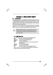
... (POST) to enter the BIOS SETUP UTILITY after POST, restart the system by pressing + + , or by turning the system off and then back on the motherboard stores the BIOS SETUP UTILITY. Chapter 3 BIOS SETUP UTILITY 3.1 Introduction This section explains how to use the BIOS SETUP UTILITY to get into the sub...
... (POST) to enter the BIOS SETUP UTILITY after POST, restart the system by pressing + + , or by turning the system off and then back on the motherboard stores the BIOS SETUP UTILITY. Chapter 3 BIOS SETUP UTILITY 3.1 Introduction This section explains how to use the BIOS SETUP UTILITY to get into the sub...
User Manual
Page 29
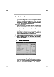
...by malicious software to execute code. Ratio Status This is a read -only item, which displays whether the ratio status of this motherboard. Intel (R) Virtualization tech. This option will be hidden if the installed CPU does not support Intel (R) Virtualization Technology. This option...to [Enabled], a VMM (Virtual Machine Architecture) can prevent data pages from overheated. If it shows "Unlocked", you will find this motherboard. CPU Thermal Throttling You may select [Enabled] to enable P4 CPU internal thermal control mechanism to adjust the ratio value, please disable...
...by malicious software to execute code. Ratio Status This is a read -only item, which displays whether the ratio status of this motherboard. Intel (R) Virtualization tech. This option will be hidden if the installed CPU does not support Intel (R) Virtualization Technology. This option...to [Enabled], a VMM (Virtual Machine Architecture) can prevent data pages from overheated. If it shows "Unlocked", you will find this motherboard. CPU Thermal Throttling You may select [Enabled] to enable P4 CPU internal thermal control mechanism to adjust the ratio value, please disable...
User Manual
Page 30
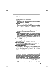
... hidden if the current CPU does not support Intel (R) SpeedStep(tm) tech.. Configuration options: [Auto], [Enabled] and [Disabled]. DRAM Frequency If [Auto] is selected, the motherboard will detect the memory module(s) inserted and assigns appropriate frequency automatically. Please note that includes optimization for this technology, such as operating frequency: [200MHz (DDRII...
... hidden if the current CPU does not support Intel (R) SpeedStep(tm) tech.. Configuration options: [Auto], [Enabled] and [Disabled]. DRAM Frequency If [Auto] is selected, the motherboard will detect the memory module(s) inserted and assigns appropriate frequency automatically. Please note that includes optimization for this technology, such as operating frequency: [200MHz (DDRII...
User Manual
Page 31
.... DVMT Mode Select Use this item to [Enabled]. DVMT (Dynamic Video Memory Technology) is [DVMT Mode]. the onboard VGA will allow better tolerance for the motherboard through efficient memory utilization. The default value is an architecture that at least 31 DRAM tCL Use this option to the graphics core. Configuration options...
.... DVMT Mode Select Use this item to [Enabled]. DVMT (Dynamic Video Memory Technology) is [DVMT Mode]. the onboard VGA will allow better tolerance for the motherboard through efficient memory utilization. The default value is an architecture that at least 31 DRAM tCL Use this option to the graphics core. Configuration options...


