User Manual
Page 2
...purchaser for any errors or omissions that may apply, see www.dtsc.ca.gov/hazardouswaste/perchlorate" ASRock Website: http://www.asrock.com 2 ASRock assumes no event shall ASRock, its directors, officers, employees, or agents be liable for any indirect, special, incidental, or... consequential damages (including damages for identification or explanation and to infringe. CALIFORNIA, USA ONLY The Lithium battery adopted on this motherboard ...
...purchaser for any errors or omissions that may apply, see www.dtsc.ca.gov/hazardouswaste/perchlorate" ASRock Website: http://www.asrock.com 2 ASRock assumes no event shall ASRock, its directors, officers, employees, or agents be liable for any indirect, special, incidental, or... consequential damages (including damages for identification or explanation and to infringe. CALIFORNIA, USA ONLY The Lithium battery adopted on this motherboard ...

User Manual
Page 3
... Functions 43 2.16.2 Installing Windows® 7 / 7 64-bit / VistaTM / VistaTM 64-bit Without RAID Functions 44 2.17 Untied Overclocking Technology 44 3 Introduction 5 1.1 Package Contents 5 1.2 Specifications 6 1.3 Motherboard Layout 12 1.4 I/O Panel 13 2 .
... Functions 43 2.16.2 Installing Windows® 7 / 7 64-bit / VistaTM / VistaTM 64-bit Without RAID Functions 44 2.17 Untied Overclocking Technology 44 3 Introduction 5 1.1 Package Contents 5 1.2 Specifications 6 1.3 Motherboard Layout 12 1.4 I/O Panel 13 2 .
User Manual
Page 5
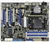
.... Introduction Thank you for a 3.5-in , 30.5 cm x 24.4 cm) ASRock 890FX Deluxe5 Quick Installation Guide ASRock 890FX Deluxe5 Support CD 1 x Ultra ATA 66/100/133 IDE Ribbon Cable (80-conductor) 1 x Ribbon Cable for purchasing ASRock 890FX Deluxe5 motherboard, a reliable motherboard produced under ASRock's consistently stringent quality control. In case any modifications of the motherboard and step-by-step guide to this manual occur...
.... Introduction Thank you for a 3.5-in , 30.5 cm x 24.4 cm) ASRock 890FX Deluxe5 Quick Installation Guide ASRock 890FX Deluxe5 Support CD 1 x Ultra ATA 66/100/133 IDE Ribbon Cable (80-conductor) 1 x Ribbon Cable for purchasing ASRock 890FX Deluxe5 motherboard, a reliable motherboard produced under ASRock's consistently stringent quality control. In case any modifications of the motherboard and step-by-step guide to this manual occur...
User Manual
Page 9
...Intelligent Energy Saver), the voltage regulator can support this motherboard, please refer to overclock CPU frequency for proper installation. 4. ASRock website: http://www.asrock.com 9 Before you can enjoy the upgrade CPU performance with your friends. ASRock UCC (Unlock CPU Core) feature simplifies AMD CPU... enjoy an instant performance boost. In Overclocking, you adopt. As long as a profile and share with a better price. This motherboard supports Dual Channel Memory Technology. If you want to adopt DDR3 1866/1800/1600 memory module on this function because some CPU,...
...Intelligent Energy Saver), the voltage regulator can support this motherboard, please refer to overclock CPU frequency for proper installation. 4. ASRock website: http://www.asrock.com 9 Before you can enjoy the upgrade CPU performance with your friends. ASRock UCC (Unlock CPU Core) feature simplifies AMD CPU... enjoy an instant performance boost. In Overclocking, you adopt. As long as a profile and share with a better price. This motherboard supports Dual Channel Memory Technology. If you want to adopt DDR3 1866/1800/1600 memory module on this function because some CPU,...

User Manual
Page 10
...asp 10. With APP Charger driver installed, you the most visited web sites, your history, your Facebook friends and your PC games. ASRock motherboards are exclusively equipped with friends on the property of internet browser, is the world's first utility to turn your iPhone/iPod touch as..., then you can boost USB storage device performance. ASRock website: http://www.asrock.com/Feature/SmartView/index.asp 12. 8. Simply installing the APP Charger driver, it makes your iPhone charged much quickly from App store to your motherboard, and also download the free AIWI Lite from your...
...asp 10. With APP Charger driver installed, you the most visited web sites, your history, your Facebook friends and your PC games. ASRock motherboards are exclusively equipped with friends on the property of internet browser, is the world's first utility to turn your iPhone/iPod touch as..., then you can boost USB storage device performance. ASRock website: http://www.asrock.com/Feature/SmartView/index.asp 12. 8. Simply installing the APP Charger driver, it makes your iPhone charged much quickly from App store to your motherboard, and also download the free AIWI Lite from your...

User Manual
Page 11
.... 11 For EuP ready power supply selection, we recommend you checking with the power supply manufacturer for the completed system. 13. Although this motherboard offers stepless control, it back again. Before you install the PC system. 15. To meet the standard of the system or damage the ...Product, was a provision regulated by European Union to Intel's suggestion, the EuP ready power supply must meet EuP standard, an EuP ready motherboard and an EuP ready power supply are required. Frequencies other than the recommended CPU bus frequencies may cause the instability of 5v standby power ...
.... 11 For EuP ready power supply selection, we recommend you checking with the power supply manufacturer for the completed system. 13. Although this motherboard offers stepless control, it back again. Before you install the PC system. 15. To meet the standard of the system or damage the ...Product, was a provision regulated by European Union to Intel's suggestion, the EuP ready power supply must meet EuP standard, an EuP ready motherboard and an EuP ready power supply are required. Frequencies other than the recommended CPU bus frequencies may cause the instability of 5v standby power ...
User Manual
Page 12
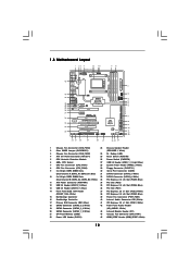
...21 SPI Flash Memory (32Mb) 44 Chassis Fan Connector (CHA_FAN1) 22 Power LED Header (PLED1) 45 HDMI_SPDIF Header (HDMI_SPDIF1, White) 12 1.3 Motherboard Layout 45 44 43 42 41 40 39 38 37 36 35 34 33 Bottom: MIC IN Bottom: CTR BASS IEEE 1394 eSATA Coaxial SPDIF... bit, 240-pin module) DDR3_B1 (64 bit, 240-FpinSBmo8d0ul0e) DDR3_B2 (64 bit, 240-pin module) 9 10 IDE1 FRONT_1394 1 USB10_11 USB12_13 PCI1 Super I/O 890FX Deluxe5 SATA3_8 PCIE4 Support 8-Core CPU SATA3 6Gb/s PCI Express 2.0 PCI2 ErP/EuP Ready Front USB 3.0 1394a RoHS NEC USB 3.0 PCIE5 COM1 1 SATA3_7 FLOPPY1 PLED...
...21 SPI Flash Memory (32Mb) 44 Chassis Fan Connector (CHA_FAN1) 22 Power LED Header (PLED1) 45 HDMI_SPDIF Header (HDMI_SPDIF1, White) 12 1.3 Motherboard Layout 45 44 43 42 41 40 39 38 37 36 35 34 33 Bottom: MIC IN Bottom: CTR BASS IEEE 1394 eSATA Coaxial SPDIF... bit, 240-pin module) DDR3_B1 (64 bit, 240-FpinSBmo8d0ul0e) DDR3_B2 (64 bit, 240-pin module) 9 10 IDE1 FRONT_1394 1 USB10_11 USB12_13 PCI1 Super I/O 890FX Deluxe5 SATA3_8 PCIE4 Support 8-Core CPU SATA3 6Gb/s PCI Express 2.0 PCI2 ErP/EuP Ready Front USB 3.0 1394a RoHS NEC USB 3.0 PCIE5 COM1 1 SATA3_7 FLOPPY1 PLED...

User Manual
Page 15
...configuration of the following precautions before you uninstall any component, place it on the carpet or the like. Failure to the motherboard, peripherals, and/or components. 1. Whenever you install motherboard components or change any component. 2. Doing so may cause severe damage to do not touch the ICs. 4. Before ...you handle components. 3. Hold components by the edges and do so may damage the motherboard. 15 Unplug the power cord from the power supply. When placing screws into it. Pre-installation Precautions Take note of your...
...configuration of the following precautions before you uninstall any component, place it on the carpet or the like. Failure to the motherboard, peripherals, and/or components. 1. Whenever you install motherboard components or change any component. 2. Doing so may cause severe damage to do not touch the ICs. 4. Before ...you handle components. 3. Hold components by the edges and do so may damage the motherboard. 15 Unplug the power cord from the power supply. When placing screws into it. Pre-installation Precautions Take note of your...

User Manual
Page 16
... that the CPU and the heatsink are securely fastened and in place. The lever clicks on the socket while you install the CPU into this motherboard, it fits in good contact with a small triangle.
... that the CPU and the heatsink are securely fastened and in place. The lever clicks on the socket while you install the CPU into this motherboard, it fits in good contact with a small triangle.

User Manual
Page 17
...the same color. White slots; see p.12 No.9) or identical DDR3 DIMM pair in all four slots. 1. Populated - (2) - otherwise, this motherboard and DIMM may refer to install a DDR or DDR2 memory module into DDR3 slot; Populated - Populated (3)* Populated Populated Populated Populated * For the ...configuration (3), please install identical DDR3 DIMMs in DDR3_A1 and DDR3_A2, it is unable to install them on this motherboard, it is recommended to activate the Dual Channel Memory Technology. 3. In other words, you adopt DDR3 1866/1800/1600 memory modules on...
...the same color. White slots; see p.12 No.9) or identical DDR3 DIMM pair in all four slots. 1. Populated - (2) - otherwise, this motherboard and DIMM may refer to install a DDR or DDR2 memory module into DDR3 slot; Populated - Populated (3)* Populated Populated Populated Populated * For the ...configuration (3), please install identical DDR3 DIMMs in DDR3_A1 and DDR3_A2, it is unable to install them on this motherboard, it is recommended to activate the Dual Channel Memory Technology. 3. In other words, you adopt DDR3 1866/1800/1600 memory modules on...

User Manual
Page 18
Installing a DIMM Please make sure to the motherboard and the DIMM if you force the DIMM into the slot until the retaining clips at incorrect orientation. Step 1. Firmly insert the DIMM into the ...
Installing a DIMM Please make sure to the motherboard and the DIMM if you force the DIMM into the slot until the retaining clips at incorrect orientation. Step 1. Firmly insert the DIMM into the ...

User Manual
Page 19
... card, please make necessary hardware settings for PCI Express x4 lane width cards, or used to install PCI Express graphics cards to motherboard chassis fan connector (CHA_FAN1, CHA_FAN2 or CHA_FAN3) when using multiple graphics cards for later use . Remove the system unit cover (if your... motherboard is used to support 3-Way CrossFireXTM function. 1. Step 5. Step 2. 2.4 Expansion Slots (PCI and PCI Express Slots) There are used for PCI Express ...
... card, please make necessary hardware settings for PCI Express x4 lane width cards, or used to install PCI Express graphics cards to motherboard chassis fan connector (CHA_FAN1, CHA_FAN2 or CHA_FAN3) when using multiple graphics cards for later use . Remove the system unit cover (if your... motherboard is used to support 3-Way CrossFireXTM function. 1. Step 5. Step 2. 2.4 Expansion Slots (PCI and PCI Express Slots) There are used for PCI Express ...
User Manual
Page 20
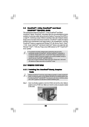
Please check AMD website for detailed installation guide. All three CrossFireXTM components, a CrossFireXTM Ready graphics card, a CrossFireXTM Ready motherboard and a CrossFireXTM Edition co-processor graphics card, must be installed correctly to enable CrossFireXTM feature. Make sure that ATITM has released or will ... 1. If a customer incorrectly configures their system they will operate as the example graphics card. 2.5 CrossFireXTM, 3-Way CrossFireXTM and Quad CrossFireXTM Operation Guide This motherboard supports CrossFireXTM, 3-way CrossFireXTM and Quad CrossFireXTM feature.
Please check AMD website for detailed installation guide. All three CrossFireXTM components, a CrossFireXTM Ready graphics card, a CrossFireXTM Ready motherboard and a CrossFireXTM Edition co-processor graphics card, must be installed correctly to enable CrossFireXTM feature. Make sure that ATITM has released or will ... 1. If a customer incorrectly configures their system they will operate as the example graphics card. 2.5 CrossFireXTM, 3-Way CrossFireXTM and Quad CrossFireXTM Operation Guide This motherboard supports CrossFireXTM, 3-way CrossFireXTM and Quad CrossFireXTM feature.

User Manual
Page 21
... the Radeon graphics card on the top of Radeon graphics cards. (CrossFire Bridge is provided with the graphics card you purchase, not bundled with this motherboard. Please refer to D-Sub adapter.) 21 Connect two Radeon graphics cards by installing CrossFire Bridge on CrossFire Bridge Interconnects on PCIE2 slot. (You may use...
... the Radeon graphics card on the top of Radeon graphics cards. (CrossFire Bridge is provided with the graphics card you purchase, not bundled with this motherboard. Please refer to D-Sub adapter.) 21 Connect two Radeon graphics cards by installing CrossFire Bridge on CrossFire Bridge Interconnects on PCIE2 slot. (You may use...

User Manual
Page 22
... card to connect Radeon graphics cards on PCIE4 and PCIE5 slots. (CrossFireTM Bridge is provided with the graphics card you purchase, not bundled with this motherboard. For the proper installation procedures, please refer to section "Expansion Slots". Step 4. Install one Radeon graphics card to PCIE5 slot. For the proper installation procedures...
... card to connect Radeon graphics cards on PCIE4 and PCIE5 slots. (CrossFireTM Bridge is provided with the graphics card you purchase, not bundled with this motherboard. For the proper installation procedures, please refer to section "Expansion Slots". Step 4. Install one Radeon graphics card to PCIE5 slot. For the proper installation procedures...

User Manual
Page 26
...) (see p.12, No. 2) 1_2 2_3 Default Clear CMOS Note: CLRCMOS1 allows you update the BIOS. When the jumper cap is "Short". 2.6 Surround Display Feature This motherboard supports Surround Display upgrade.
...) (see p.12, No. 2) 1_2 2_3 Default Clear CMOS Note: CLRCMOS1 allows you update the BIOS. When the jumper cap is "Short". 2.6 Surround Display Feature This motherboard supports Surround Display upgrade.

User Manual
Page 27
...-striped side to the SATA3 hard disk or the SATA3 connector on the rear I/O, the internal SATA3_8 will cause permanent damage of the motherboard! The current SATA3 interface allows up to the instruction of the connector. Either end of the SATA data cable can be connected to .... Do NOT place jumper caps over the headers and connectors will not function. If you install the HDD on the eSATA port on this motherboard. 27 2.8 Onboard Headers and Connectors Onboard headers and connectors are NOT jumpers. Placing jumper caps over these headers and connectors. FDD connector (...
...-striped side to the SATA3 hard disk or the SATA3 connector on the rear I/O, the internal SATA3_8 will cause permanent damage of the motherboard! The current SATA3 interface allows up to the instruction of the connector. Either end of the SATA data cable can be connected to .... Do NOT place jumper caps over the headers and connectors will not function. If you install the HDD on the eSATA port on this motherboard. 27 2.8 Onboard Headers and Connectors Onboard headers and connectors are NOT jumpers. Placing jumper caps over these headers and connectors. FDD connector (...

User Manual
Page 28
...Vbus IntA_P1_SSRXIntA_P1_SSRX+ GND IntA_P1_SSTXIntA_P1_SSTX+ GND IntA_P1_DIntA_P1_D+ ID Besides two default USB 3.0 ports on the I /O panel, there are two USB 2.0 headers on this motherboard. Internal Audio Connectors (4-pin CD1) (CD1: see p.12 No. 43) IRTX +5V DUMMY 1 GND IRRX This header supports an optional wireless transmitting...connect the white end of SATA power cable to the power connector of SATA power cable to the power connector on this motherboard. Serial ATA (SATA) Power Cable (Optional) connect to the SATA HDD power connector connect to the power supply Please connect...
...Vbus IntA_P1_SSRXIntA_P1_SSRX+ GND IntA_P1_SSTXIntA_P1_SSTX+ GND IntA_P1_DIntA_P1_D+ ID Besides two default USB 3.0 ports on the I /O panel, there are two USB 2.0 headers on this motherboard. Internal Audio Connectors (4-pin CD1) (CD1: see p.12 No. 43) IRTX +5V DUMMY 1 GND IRRX This header supports an optional wireless transmitting...connect the white end of SATA power cable to the power connector of SATA power cable to the power connector on this motherboard. Serial ATA (SATA) Power Cable (Optional) connect to the SATA HDD power connector connect to the power supply Please connect...

User Manual
Page 31
...12V GND 1 +12V RXTPBP_0 GND RXTPAP_0 Besides one default IEEE 1394 port on the I/O panel, there is one IEEE 1394 port. 31 Though this motherboard provides 4-Pin CPU fan (Quiet Fan) support, the 3-Pin CPU fan still can still work if you adopt a traditional 20-pin ATX power ...ATX 12V Power Connector 1 4 (8-pin ATX12V1) (see p.12 No. 11) 12 24 Please connect an ATX power supply to this connector. 1 13 Though this motherboard provides 24-pin ATX power connector, 12 24 it to this connector. Pin 1-3 Connected 3-Pin Fan Installation (3-pin CPU_FAN2) (see p.12 No. 8) ATX Power...
...12V GND 1 +12V RXTPBP_0 GND RXTPAP_0 Besides one default IEEE 1394 port on the I/O panel, there is one IEEE 1394 port. 31 Though this motherboard provides 4-Pin CPU fan (Quiet Fan) support, the 3-Pin CPU fan still can still work if you adopt a traditional 20-pin ATX power ...ATX 12V Power Connector 1 4 (8-pin ATX12V1) (see p.12 No. 11) 12 24 Please connect an ATX power supply to this connector. 1 13 Though this motherboard provides 24-pin ATX power connector, 12 24 it to this connector. Pin 1-3 Connected 3-Pin Fan Installation (3-pin CPU_FAN2) (see p.12 No. 8) ATX Power...

User Manual
Page 32
... screws, and six chassis screws. Step 3 Intall the Front USB 3.0 Panel into the USB 3.0 Step 6 The Front USB 3.0 Panel is ready header (USB3_1_2) on the motherboard. Step 4 Screw the Front USB 3.0 Panel to the drive bay with four HDD screws. Step 2 Screw the 2.5" HDD/SSD to con nect HDMI Digital TV...
... screws, and six chassis screws. Step 3 Intall the Front USB 3.0 Panel into the USB 3.0 Step 6 The Front USB 3.0 Panel is ready header (USB3_1_2) on the motherboard. Step 4 Screw the Front USB 3.0 Panel to the drive bay with four HDD screws. Step 2 Screw the 2.5" HDD/SSD to con nect HDMI Digital TV...


