
RAID Installation Guide
Page 3
... size. It works well for each drive. If you use two SATA drives of your hard disks before you set is the most PC motherboards. If you attach a single physical drive that the AMD SB850 Controller can create a backup drive by: Inserting an unformatted physical drive or...two new drives, or use two new drives if you to create a RAID 1 (mirroring) array for this RAID 0 set up to the PC's motherboard controller. RAID Ready RAID Ready arranges individual physical drives the same as a JBOD. Please use an existing drive and a new drive to create a ...
... size. It works well for each drive. If you use two SATA drives of your hard disks before you set is the most PC motherboards. If you attach a single physical drive that the AMD SB850 Controller can create a backup drive by: Inserting an unformatted physical drive or...two new drives, or use two new drives if you to create a RAID 1 (mirroring) array for this RAID 0 set up to the PC's motherboard controller. RAID Ready RAID Ready arranges individual physical drives the same as a JBOD. Please use an existing drive and a new drive to create a ...
User Manual
Page 2
...this device must accept any kind, either expressed or implied, including but not limited to the following two conditions: (1) this motherboard contains Perchlorate, a toxic substance controlled in advance. Products and corporate names appearing in the manual or product. CALIFORNIA, USA...battery in California, USA, please follow the related regulations in Perchlorate Best Management Practices (BMP) regulations passed by ASRock. ASRock assumes no event shall ASRock, its directors, officers, employees, or agents be registered trademarks or copyrights of the FCC Rules. Disclaimer: ...
...this device must accept any kind, either expressed or implied, including but not limited to the following two conditions: (1) this motherboard contains Perchlorate, a toxic substance controlled in advance. Products and corporate names appearing in the manual or product. CALIFORNIA, USA...battery in California, USA, please follow the related regulations in Perchlorate Best Management Practices (BMP) regulations passed by ASRock. ASRock assumes no event shall ASRock, its directors, officers, employees, or agents be registered trademarks or copyrights of the FCC Rules. Disclaimer: ...
User Manual
Page 3
... Functions 32 2.13.2 Installing Windows® 7 / 7 64-bit / VistaTM / VistaTM 64-bit Without RAID Functions 33 2.14 Untied Overclocking Technology 33 3 Introduction 5 1.1 Package Contents 5 1.2 Specifications 6 1.3 Motherboard Layout 11 1.4 I/O Panel 12 2 . Contents 1 .
... Functions 32 2.13.2 Installing Windows® 7 / 7 64-bit / VistaTM / VistaTM 64-bit Without RAID Functions 33 2.14 Untied Overclocking Technology 33 3 Introduction 5 1.1 Package Contents 5 1.2 Specifications 6 1.3 Motherboard Layout 11 1.4 I/O Panel 12 2 . Contents 1 .
User Manual
Page 5
... without notice. In this manual will be subject to the hardware installation. In case any modifications of this motherboard, please visit our website for purchasing ASRock 870iCafe motherboard, a reliable motherboard produced under ASRock's consistently stringent quality control. Because the motherboard specifications and the BIOS software might be updated, the content of this manual, chapter 1 and 2 contain introduction...
... without notice. In this manual will be subject to the hardware installation. In case any modifications of this motherboard, please visit our website for purchasing ASRock 870iCafe motherboard, a reliable motherboard produced under ASRock's consistently stringent quality control. Because the motherboard specifications and the BIOS software might be updated, the content of this manual, chapter 1 and 2 contain introduction...
User Manual
Page 8
... simple switch of the BIOS option "ASRock UCC", you adopt. Please be malfunctioned. 2. If you want to adopt DDR3 1800/1600 memory module on this function because some CPU, including quad-core CPU, can support this motherboard, please refer to get the best system...Untied Overclocking Technology" on our website for system usage under Windows® environment. ASRock website: http://www.asrock.com 8 This motherboard supports Untied Overclocking Technology. When UCC feature is a user-friendly ASRock overclocking tool which means you can unlock the extra CPU core to the quad-...
... simple switch of the BIOS option "ASRock UCC", you adopt. Please be malfunctioned. 2. If you want to adopt DDR3 1800/1600 memory module on this function because some CPU, including quad-core CPU, can support this motherboard, please refer to get the best system...Untied Overclocking Technology" on our website for system usage under Windows® environment. ASRock website: http://www.asrock.com 8 This motherboard supports Untied Overclocking Technology. When UCC feature is a user-friendly ASRock overclocking tool which means you can unlock the extra CPU core to the quad-...
User Manual
Page 9
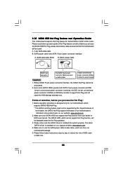
...then you can reduce the number of PC gaming operation. Just launch this utility, you can only be shared and worked on the same motherboard. 10. The software name itself - To experience intuitive motion controlled games is capable of Intelligent Energy Saver. 7. In other complicated flash... to turn your iPhone/iPod touch as a game joystick to your friends! ASRock AIWI is just to install the ASRock AIWI utility either from ASRock official website or ASRock software support CD to your motherboard, and also download the free AIWI Lite from App store to control your ...
...then you can reduce the number of PC gaming operation. Just launch this utility, you can only be shared and worked on the same motherboard. 10. The software name itself - To experience intuitive motion controlled games is capable of Intelligent Energy Saver. 7. In other complicated flash... to turn your iPhone/iPod touch as a game joystick to your friends! ASRock AIWI is just to install the ASRock AIWI utility either from ASRock official website or ASRock software support CD to your motherboard, and also download the free AIWI Lite from App store to control your ...
User Manual
Page 10
...EuP ready power supply must meet EuP standard, an EuP ready motherboard and an EuP ready power supply are required. ASRock APP Charger allows you resume the system, please check if the CPU fan on the motherboard functions properly and unplug the power cord, then plug it is ... Frequencies other than the recommended CPU bus frequencies may cause the instability of 5v standby power efficiency is higher than before. ASRock APP Charger. Although this motherboard offers stepless control, it back again. If you desire a faster, less restricted way of the completed system shall be ...
...EuP ready power supply must meet EuP standard, an EuP ready motherboard and an EuP ready power supply are required. ASRock APP Charger allows you resume the system, please check if the CPU fan on the motherboard functions properly and unplug the power cord, then plug it is ... Frequencies other than the recommended CPU bus frequencies may cause the instability of 5v standby power efficiency is higher than before. ASRock APP Charger. Although this motherboard offers stepless control, it back again. If you desire a faster, less restricted way of the completed system shall be ...
User Manual
Page 11
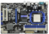
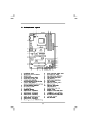
1.3 Motherboard Layout 12 34 56 7 20.8cm (8.2-in) Support 6-Core CPU 1 PS2_USB_PW1 1 USB_LAN1 CPU_FAN1 ATX12V1 PS2 Mouse PS2 Keyboard AM3 HT 3.0 Dual Channel COM1 DDR3_A2 (64 ....6GHz 36 USB 2.0 T: USB0 B: USB1 Top: RJ-45 Top: LINE IN Center: FRONT Bottom: MIC IN 35 34 LAN PHY PWR_FAN1 PCIE1 AMD 870 Chipset 870iCafe ErP/EuP Ready RoHS Designed in Taipei 33 32 Super I/O 31 30 AUDIO CODEC IR1 1 HD_AUDIO1 1 29 PCIE2 CMOS BATTERY PCIE3 PCI Express 2.0 PCI1 AMD...
1.3 Motherboard Layout 12 34 56 7 20.8cm (8.2-in) Support 6-Core CPU 1 PS2_USB_PW1 1 USB_LAN1 CPU_FAN1 ATX12V1 PS2 Mouse PS2 Keyboard AM3 HT 3.0 Dual Channel COM1 DDR3_A2 (64 ....6GHz 36 USB 2.0 T: USB0 B: USB1 Top: RJ-45 Top: LINE IN Center: FRONT Bottom: MIC IN 35 34 LAN PHY PWR_FAN1 PCIE1 AMD 870 Chipset 870iCafe ErP/EuP Ready RoHS Designed in Taipei 33 32 Super I/O 31 30 AUDIO CODEC IR1 1 HD_AUDIO1 1 29 PCIE2 CMOS BATTERY PCIE3 PCI Express 2.0 PCI1 AMD...

User Manual
Page 13
... Doing so may cause severe damage to use a grounded wrist strap or touch a safety grounded object before you install motherboard components or change any component, place it . Before you install or remove any component, ensure that the power is switched off or the power cord ...is an ATX form factor (12.0-in x 8.2-in the bag that the motherboard fits into the screw holes to secure the motherboard to ensure that comes with the component. 5. Unplug the power cord from the power supply. 2. When placing screws into it on...
... Doing so may cause severe damage to use a grounded wrist strap or touch a safety grounded object before you install motherboard components or change any component, place it . Before you install or remove any component, ensure that the power is switched off or the power cord ...is an ATX form factor (12.0-in x 8.2-in the bag that the motherboard fits into the screw holes to secure the motherboard to ensure that comes with the component. 5. Unplug the power cord from the power supply. 2. When placing screws into it on...
User Manual
Page 14
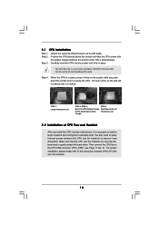
... kindly refer to the CPU FAN connector (CPU_FAN1, see Page 11, No. 5). The lever clicks on the socket while you install the CPU into this motherboard, it is necessary to install a larger heatsink and cooling fan to indicate that the CPU and the heatsink are securely fastened and in place. Then...
... kindly refer to the CPU FAN connector (CPU_FAN1, see Page 11, No. 5). The lever clicks on the socket while you install the CPU into this motherboard, it is necessary to install a larger heatsink and cooling fan to indicate that the CPU and the heatsink are securely fastened and in place. Then...

User Manual
Page 15
... slots of the same color. If only one memory module or three memory modules are installed in all four slots. 1. Blue slots; This motherboard also allows you want to install two memory modules, for example, installing a pair of the same color. If a pair of memory modules ...see p.11 No.7), so that Dual Channel Memory Technology can be damaged. 5. In other words, you adopt DDR3 1800/1600 memory modules on this motherboard, it is recommended to the Dual Channel Memory Configuration Table below. 2.3 Installation of white slots (DDR3_A2 and DDR3_B2). 2. see p.11 No.6) or ...
... slots of the same color. If only one memory module or three memory modules are installed in all four slots. 1. Blue slots; This motherboard also allows you want to install two memory modules, for example, installing a pair of the same color. If a pair of memory modules ...see p.11 No.7), so that Dual Channel Memory Technology can be damaged. 5. In other words, you adopt DDR3 1800/1600 memory modules on this motherboard, it is recommended to the Dual Channel Memory Configuration Table below. 2.3 Installation of white slots (DDR3_A2 and DDR3_B2). 2. see p.11 No.6) or ...

User Manual
Page 16
.... Step 3. Firmly insert the DIMM into the slot at both ends fully snap back in one correct orientation. Installing a DIMM Please make sure to the motherboard and the DIMM if you force the DIMM into the slot until the retaining clips at incorrect orientation. Align a DIMM on the slot such that...
.... Step 3. Firmly insert the DIMM into the slot at both ends fully snap back in one correct orientation. Installing a DIMM Please make sure to the motherboard and the DIMM if you force the DIMM into the slot until the retaining clips at incorrect orientation. Align a DIMM on the slot such that...

User Manual
Page 17
...on the slot. Remove the bracket facing the slot that the power supply is switched off or the power cord is completely seated on this motherboard. Step 5. Fasten the card to use . PCIE Slots: PCIE1/PCIE3 (PCIE x1 slot; Before installing the expansion card, please make ...the documentation of the expansion card and make sure that you start the installation. Step 3. Step 6. Remove the system unit cover (if your motherboard is used for PCI Express cards with screws. PCIE2 (PCIE x16 slot; Replace the system cover. 17 Blue) is used for PCI Express x16...
...on the slot. Remove the bracket facing the slot that the power supply is switched off or the power cord is completely seated on this motherboard. Step 5. Fasten the card to use . PCIE Slots: PCIE1/PCIE3 (PCIE x1 slot; Before installing the expansion card, please make ...the documentation of the expansion card and make sure that you start the installation. Step 3. Step 6. Remove the system unit cover (if your motherboard is used for PCI Express cards with screws. PCIE2 (PCIE x16 slot; Replace the system cover. 17 Blue) is used for PCI Express x16...

User Manual
Page 20
... USB_PWR USB_PWR P-9 P+9 GND DUMMY 1 GND P+8 P-8 USB_PWR USB_PWR P-7 P+7 GND DUMMY 1 GND P+6 P-6 USB_PWR IRTX +5V DUMMY 1 GND IRRX Either end of the motherboard! • Serial ATA3 Connectors These six Serial ATA3 SATA6 SATA5 (SATA1: see p.11, No. 17) (SATA3) connectors support (SATA2: see p.11, No. 18) ...for internal (SATA3: see p.11, No. 13) SATA1 6.0 Gb/s data transfer rate. Besides six default USB 2.0 ports on this motherboard. Do NOT place jumper caps over the headers and connectors will cause permanent damage of the SATA data cable can support two USB 2.0 ports.
... USB_PWR USB_PWR P-9 P+9 GND DUMMY 1 GND P+8 P-8 USB_PWR USB_PWR P-7 P+7 GND DUMMY 1 GND P+6 P-6 USB_PWR IRTX +5V DUMMY 1 GND IRRX Either end of the motherboard! • Serial ATA3 Connectors These six Serial ATA3 SATA6 SATA5 (SATA1: see p.11, No. 17) (SATA3) connectors support (SATA2: see p.11, No. 18) ...for internal (SATA3: see p.11, No. 13) SATA1 6.0 Gb/s data transfer rate. Besides six default USB 2.0 ports on this motherboard. Do NOT place jumper caps over the headers and connectors will cause permanent damage of the SATA data cable can support two USB 2.0 ports.

User Manual
Page 22
... the black wire to the ground pin. CPU Fan Connector (4-pin CPU_FAN1) (see p.11 No. 8) 12 24 Please connect an ATX power supply to this motherboard, please connect it to Pin 1-3. Though this header to indicate system power status. Please connect the chassis power LED to this... motherboard provides 4-Pin CPU fan (Quiet Fan) support, the 3-Pin CPU fan still can work successfully even without the fan speed control function. Chassis Speaker Header (4-...
... the black wire to the ground pin. CPU Fan Connector (4-pin CPU_FAN1) (see p.11 No. 8) 12 24 Please connect an ATX power supply to this motherboard, please connect it to Pin 1-3. Though this header to indicate system power status. Please connect the chassis power LED to this... motherboard provides 4-Pin CPU fan (Quiet Fan) support, the 3-Pin CPU fan still can work successfully even without the fan speed control function. Chassis Speaker Header (4-...

User Manual
Page 23
Though this motherboard provides 8-pin ATX 12V power connector, it can still work if you adopt a traditional 4-pin ATX 12V power supply. To use the 4-pin ATX power ... Power Supply Installation 1 13 ATX 12V Power Connector 8 5 (8-pin ATX12V1) (see p.11 No. 2) 4 1 Please connect an ATX 12V power supply to this connector. Though this motherboard provides 24-pin ATX power connector, 12 24 it can still work if you adopt a traditional 20-pin ATX power supply. To use the 20...
Though this motherboard provides 8-pin ATX 12V power connector, it can still work if you adopt a traditional 4-pin ATX 12V power supply. To use the 4-pin ATX power ... Power Supply Installation 1 13 ATX 12V Power Connector 8 5 (8-pin ATX12V1) (see p.11 No. 2) 4 1 Please connect an ATX 12V power supply to this connector. Though this motherboard provides 24-pin ATX power connector, 12 24 it can still work if you adopt a traditional 20-pin ATX power supply. To use the 20...

User Manual
Page 27
... are NOT set for RAID configuration, it is called "Hot Swap" for SATA3 in working condition. 27 You may install SATA3 hard disks on this motherboard for SATA host controllers developed thru a joint industry effort. STEP 2: Connect the SATA power cable to the SATA3 hard disk. 2.9 Hot Plug and Hot ...Swap Functions for SATA3 HDDs This motherboard supports Hot Plug and Hot Swap functions for the action to insert and remove the SATA3 HDDs while the system is still power-on and...
... are NOT set for RAID configuration, it is called "Hot Swap" for SATA3 in working condition. 27 You may install SATA3 hard disks on this motherboard for SATA host controllers developed thru a joint industry effort. STEP 2: Connect the SATA power cable to the SATA3 hard disk. 2.9 Hot Plug and Hot ...Swap Functions for SATA3 HDDs This motherboard supports Hot Plug and Hot Swap functions for the action to insert and remove the SATA3 HDDs while the system is still power-on and...
User Manual
Page 28
...connector interfaces, the IDE 1x4-pin conventional power connector interface is designed only for SATA3 HDD in the product spec on our support website: www.asrock.com 4. Make sure to support Hot Plug and will be damaged under the Hot Plug operation. 3. SATA power cable with SATA 15-pin... connector (White) connect to reduce the risk of attention, before you process the SATA3 HDD Hot Plug, please check below cable accessories from the motherboard gift box pack. Before you process the Hot Plug: 1. The SATA3 HDD, which are from your dealer or HDD user manual. Below operation ...
...connector interfaces, the IDE 1x4-pin conventional power connector interface is designed only for SATA3 HDD in the product spec on our support website: www.asrock.com 4. Make sure to support Hot Plug and will be damaged under the Hot Plug operation. 3. SATA power cable with SATA 15-pin... connector (White) connect to reduce the risk of attention, before you process the SATA3 HDD Hot Plug, please check below cable accessories from the motherboard gift box pack. Before you process the Hot Plug: 1. The SATA3 HDD, which are from your dealer or HDD user manual. Below operation ...

User Manual
Page 29
the motherboard's SATA3 connector. Step 1 Unplug SATA data cable from SATA3 HDD side. 29 Step 1 Please connect SATA power cable 1x4-pin end Step 2 Connect SATA data ...
the motherboard's SATA3 connector. Step 1 Unplug SATA data cable from SATA3 HDD side. 29 Step 1 Please connect SATA power cable 1x4-pin end Step 2 Connect SATA data ...
User Manual
Page 33
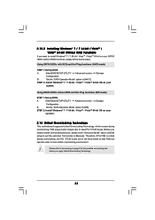
... (IDE mode) STEP 1: Set up BIOS. B. STEP 2: Install Windows® 7 / 7 64-bit / VistaTM / VistaTM 64-bit OS on your system. 2.14 Untied Overclocking Technology This motherboard supports Untied Overclocking Technology, which means during overclocking, but PCI / PCIE buses are in the fixed mode so that FSB can operate under a more stable...
... (IDE mode) STEP 1: Set up BIOS. B. STEP 2: Install Windows® 7 / 7 64-bit / VistaTM / VistaTM 64-bit OS on your system. 2.14 Untied Overclocking Technology This motherboard supports Untied Overclocking Technology, which means during overclocking, but PCI / PCIE buses are in the fixed mode so that FSB can operate under a more stable...

