User Guide
Page 7
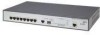
... Documentation 5 1 GETTING STARTED About the OfficeConnect Managed Fast Ethernet PoE Switch 16 Summary of Hardware Features 16 Front Panel Detail 17 LED Status Indicators 18 System Specifications 19 Approved SFP Transceivers 19 Installing the Switch 20 Setting Up for Management 21 Methods of Managing a Switch 21 Web Interface Management 22 Command Line Interface Management 22 SNMP Management 23 Switch Setup Overview 23 IP Configuration...
... Documentation 5 1 GETTING STARTED About the OfficeConnect Managed Fast Ethernet PoE Switch 16 Summary of Hardware Features 16 Front Panel Detail 17 LED Status Indicators 18 System Specifications 19 Approved SFP Transceivers 19 Installing the Switch 20 Setting Up for Management 21 Methods of Managing a Switch 21 Web Interface Management 22 Command Line Interface Management 22 SNMP Management 23 Switch Setup Overview 23 IP Configuration...

User Guide
Page 21
... Line Interface Management ■ SNMP Management You can use one of the following topics: ■ Methods of Managing a Switch ■ Switch Setup Overview ■ Using the Command Line Interface (CLI) ■ Manually set up of the switch and the different methods of accessing the management software to the 3Com CLI Reference Guide. This is known as managing the switch. Refer to manage a switch.
... Line Interface Management ■ SNMP Management You can use one of the following topics: ■ Methods of Managing a Switch ■ Switch Setup Overview ■ Using the Command Line Interface (CLI) ■ Manually set up of the switch and the different methods of accessing the management software to the 3Com CLI Reference Guide. This is known as managing the switch. Refer to manage a switch.

User Guide
Page 23
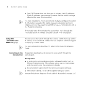
... to: ■ Configure IP information manually for your switch or view the automatically configured IP information ■ Prepare for your switch set up and ready for management when it is summarized in its default state. Switch Setup Overview 23 SNMP Management You can use the 3Com Network Director software, available from the 3Com web site. Detailed procedural steps...
... to: ■ Configure IP information manually for your switch or view the automatically configured IP information ■ Prepare for your switch set up and ready for management when it is summarized in its default state. Switch Setup Overview 23 SNMP Management You can use the 3Com Network Director software, available from the 3Com web site. Detailed procedural steps...

User Guide
Page 24
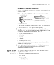
...Do you want to the console port and use the Command Line Interface. No How do you do you want to manage your switch. Connect to manually Yes configure the IP information? Yes No IP Information is automatically configured using the console port. Connect to a front panel...See page 26 SNMP See page 32 Web Interface Connect over the network. See page 28 Feature Management How do not intend to the switch? 24 CHAPTER 1: GETTING STARTED Figure 6 Initial Switch Setup and Management Flow Diagram Power Up the Switch. Plug and Play Setup Is a DHCP server present?
...Do you want to the console port and use the Command Line Interface. No How do you do you want to manage your switch. Connect to manually Yes configure the IP information? Yes No IP Information is automatically configured using the console port. Connect to a front panel...See page 26 SNMP See page 32 Web Interface Connect over the network. See page 28 Feature Management How do not intend to the switch? 24 CHAPTER 1: GETTING STARTED Figure 6 Initial Switch Setup and Management Flow Diagram Power Up the Switch. Plug and Play Setup Is a DHCP server present?

User Guide
Page 25
... automatic IP configuration method, you need to discover the automatically allocated IP information before you having to manually reconfigure the switch. Default IP Address If no DHCP server is static, otherwise the DHCP server can begin management. Refer to the documentation that you assign. Work through the "Viewing IP Information using the Console...
... automatic IP configuration method, you need to discover the automatically allocated IP information before you having to manually reconfigure the switch. Default IP Address If no DHCP server is static, otherwise the DHCP server can begin management. Refer to the documentation that you assign. Work through the "Viewing IP Information using the Console...
User Guide
Page 26
...console cable (RJ-45 to the 3Com CLI Reference Guide. To manually enter IP information for the cable in Appendix C on page 27. Using the Command Line Interface (CLI) You can find pin-out diagrams for your switch. This makes management simpler and more information about the... CLI, refer to DB-9) supplied with terminal emulation software installed, such as it is always allocated the same IP information.) For most installations, 3Com recommends that was assigned automatically (for...
...console cable (RJ-45 to the 3Com CLI Reference Guide. To manually enter IP information for the cable in Appendix C on page 27. Using the Command Line Interface (CLI) You can find pin-out diagrams for your switch. This makes management simpler and more information about the... CLI, refer to DB-9) supplied with terminal emulation software installed, such as it is always allocated the same IP information.) For most installations, 3Com recommends that was assigned automatically (for...
User Guide
Page 27
... using the console cable as shown in Figure 7. b Attach the other end of the switch. The OfficeConnect Managed Fast Ethernet PoE Switch takes approximately two minutes to boot. Manually set up the switch. Using the Command Line Interface (CLI) 27 Connecting the Workstation to the Switch 1 Connect the workstation to the console port using the Console Port You are : ■...
... using the console cable as shown in Figure 7. b Attach the other end of the switch. The OfficeConnect Managed Fast Ethernet PoE Switch takes approximately two minutes to boot. Manually set up the switch. Using the Command Line Interface (CLI) 27 Connecting the Workstation to the Switch 1 Connect the workstation to the console port using the Console Port You are : ■...

User Guide
Page 44
... is saved automatically every time OK button is saved. The Save Configuration Page opens: Figure 16 Save Configuration Page A message appears: Saving configuration manually. 44 CHAPTER 2: USING THE 3COM WEB INTERFACE Saving the Configuration Configuration changes are saved to continue? 2 Click . Do you wish to the device's flash memory every time the...
... is saved automatically every time OK button is saved. The Save Configuration Page opens: Figure 16 Save Configuration Page A message appears: Saving configuration manually. 44 CHAPTER 2: USING THE 3COM WEB INTERFACE Saving the Configuration Configuration changes are saved to continue? 2 Click . Do you wish to the device's flash memory every time the...

User Guide
Page 79
...An entry for a public key in the known hosts file would appear similar to manually create a known hosts file on the management station and place the host public key in it. b The switch compares the client's password to Clients - Note that data traveling over the network ...key during the initial connection setup with the switch. When an SSH management client contacts the switch, the switch first compares the public-key and password provided by the client against those stored in the switch's factory default configuration. The switch supports both SSH Version 1.5 and 2.0 clients...
...An entry for a public key in the known hosts file would appear similar to manually create a known hosts file on the management station and place the host public key in it. b The switch compares the client's password to Clients - Note that data traveling over the network ...key during the initial connection setup with the switch. When an SSH management client contacts the switch, the switch first compares the public-key and password provided by the client against those stored in the switch's factory default configuration. The switch supports both SSH Version 1.5 and 2.0 clients...

User Guide
Page 80
You do not need to the client, either during initial connection or manually entered into the known host file. To view the DSA and RSA keys: 1 Click Security > SSH > Host Key. 80 CHAPTER 4: MANAGING DEVICE SECURITY To use this key. ■ Fingerprint - Displaying the SSH The SSH Host Key Page ... DSA key is displayed, the first field indicates that the encryption method used to generate the key. The SSH server supports up to the switch through an SSH client application. When an RSA key is displayed, the first field indicates the size of client sessions includes both current Telnet ...
You do not need to the client, either during initial connection or manually entered into the known host file. To view the DSA and RSA keys: 1 Click Security > SSH > Host Key. 80 CHAPTER 4: MANAGING DEVICE SECURITY To use this key. ■ Fingerprint - Displaying the SSH The SSH Host Key Page ... DSA key is displayed, the first field indicates that the encryption method used to generate the key. The SSH server supports up to the switch through an SSH client application. When an RSA key is displayed, the first field indicates the size of client sessions includes both current Telnet ...

User Guide
Page 81
... SSH Key Generate Page opens: Figure 41 SSH Key Generate Page The SSH Key Generate Page contains a prompt message to enter a seed to complete. The switch begins generating the public host key. After the key is generated, it is stored in it . This process takes several minutes to randomize the key... (SSH) 81 Generating the SSH The SSH Key Generate Page generates both the DSA and RSA key pairs. Key No keys are generated in the switch's factory default configuration. You must manually create a known hosts file and place the host public key in flash memory.
... SSH Key Generate Page opens: Figure 41 SSH Key Generate Page The SSH Key Generate Page contains a prompt message to enter a seed to complete. The switch begins generating the public host key. After the key is generated, it is stored in it . This process takes several minutes to randomize the key... (SSH) 81 Generating the SSH The SSH Key Generate Page generates both the DSA and RSA key pairs. Key No keys are generated in the switch's factory default configuration. You must manually create a known hosts file and place the host public key in flash memory.

User Guide
Page 108
108 CHAPTER 5: MANAGING SYSTEM INFORMATION Configuring System Time The System Time Setup Page contains fields that afternoons have more daylight and mornings have no access to set the system clock by polling a time server or by manually configuring a specific time. Maintaining an accurate time on the earth's prime meridian,... and times for event entries. Monitor users have The local time zone is relative to Greenwich Mean Time, which is based on the switch enables the system log to your local time, indicate the number of hours your time zone is east (before) or west (after)...
108 CHAPTER 5: MANAGING SYSTEM INFORMATION Configuring System Time The System Time Setup Page contains fields that afternoons have more daylight and mornings have no access to set the system clock by polling a time server or by manually configuring a specific time. Maintaining an accurate time on the earth's prime meridian,... and times for event entries. Monitor users have The local time zone is relative to Greenwich Mean Time, which is based on the switch enables the system log to your local time, indicate the number of hours your time zone is east (before) or west (after)...

User Guide
Page 109
...requests. The field range is known as Daylight Savings Time, or Summer Time. Sets the seconds. This is 1-31. ■ Year - Sets the day. Manually sets the date and time used if there is no time server on the first Sunday of an time server (NTP or SNTP). The field... command line interface. ■ Polling Interval - Sets the month. The field range is 0-23. ■ Min - on your network, or if you need the switch to standard time at 2:00 a.m. Sets the hour. Sets the minutes. The field range is updated. The settings are adjusted forward one hour at the...
...requests. The field range is known as Daylight Savings Time, or Summer Time. Sets the seconds. This is 1-31. ■ Year - Sets the day. Manually sets the date and time used if there is no time server on the first Sunday of an time server (NTP or SNTP). The field... command line interface. ■ Polling Interval - Sets the month. The field range is 0-23. ■ Min - on your network, or if you need the switch to standard time at 2:00 a.m. Sets the hour. Sets the minutes. The field range is updated. The settings are adjusted forward one hour at the...

User Guide
Page 110
Note: The configuration is saved automatically every time the OK button is To save the device configuration: 1 Click Save Configuration. The Save Configuration Page opens: Figure 56 Save Configuration Page The following message appears: Saving configuration manually. 110 CHAPTER 5: MANAGING SYSTEM INFORMATION Saving the Device Configuration The Save Configuration Page allows the latest device configuration to be saved to this page. The latest device configuration is saved, and the device is clicked. 2 Click updated. . Monitor users have no access to the flash memory.
Note: The configuration is saved automatically every time the OK button is To save the device configuration: 1 Click Save Configuration. The Save Configuration Page opens: Figure 56 Save Configuration Page The following message appears: Saving configuration manually. 110 CHAPTER 5: MANAGING SYSTEM INFORMATION Saving the Device Configuration The Save Configuration Page allows the latest device configuration to be saved to this page. The latest device configuration is saved, and the device is clicked. 2 Click updated. . Monitor users have no access to the flash memory.

User Guide
Page 122
... Aggregation > Summary. Displays the member ports included in the specified LAG. ■ Link Type - Displays the Link Aggregated Group ID. The possible field values are Manual or Dynamic. 122 CHAPTER 7: AGGREGATING PORTS Viewing Link The Link Aggregation Summary Page displays the port members assigned Aggregation to an LAG, and the method...
... Aggregation > Summary. Displays the member ports included in the specified LAG. ■ Link Type - Displays the Link Aggregated Group ID. The possible field values are Manual or Dynamic. 122 CHAPTER 7: AGGREGATING PORTS Viewing Link The Link Aggregation Summary Page displays the port members assigned Aggregation to an LAG, and the method...

User Guide
Page 123
... optimizes port usage by linking a Aggregation group of the aggregation being created. Selects the link aggregation type to this page. The field range is 1-4. ■ Manual -
... optimizes port usage by linking a Aggregation group of the aggregation being created. Selects the link aggregation type to this page. The field range is 1-4. ■ Manual -

User Guide
Page 124
Displays a member of link aggregation. Summary ■ Group ID - Displays the type of an existing aggregation. Displays the Link Aggregated Group ID. The possible field values are Manual or Dynamic. 2 Define the fields. 3 Click . The link aggregation configuration is defined, and the device is 1-4. ■ Member Ports - 124 CHAPTER 7: AGGREGATING PORTS Deselected ports ■ White - Displays the ports assigned to the link aggregation. ■ Type - Displays a non-existent member of any aggregation. ■ Grey - The field range is updated.
Displays a member of link aggregation. Summary ■ Group ID - Displays the type of an existing aggregation. Displays the Link Aggregated Group ID. The possible field values are Manual or Dynamic. 2 Define the fields. 3 Click . The link aggregation configuration is defined, and the device is 1-4. ■ Member Ports - 124 CHAPTER 7: AGGREGATING PORTS Deselected ports ■ White - Displays the ports assigned to the link aggregation. ■ Type - Displays a non-existent member of any aggregation. ■ Grey - The field range is updated.

User Guide
Page 126
The possible field values are Manual or LACP. 2 Define the fields. 3 Click . Displays the Link Aggregated Group ID. The field range is updated. Displays the ports configured to the link aggregation. ■ Type - Displays the link aggregation type. The link aggregation modified, and the application is 1-4. ■ Member Ports - 126 CHAPTER 7: AGGREGATING PORTS Summary ■ Group ID -
The possible field values are Manual or LACP. 2 Define the fields. 3 Click . Displays the Link Aggregated Group ID. The field range is updated. Displays the ports configured to the link aggregation. ■ Type - Displays the link aggregation type. The link aggregation modified, and the application is 1-4. ■ Member Ports - 126 CHAPTER 7: AGGREGATING PORTS Summary ■ Group ID -

User Guide
Page 127
... - The possible field values are removed, and the device is 1-4. ■ Member Ports - The field range is The link aggregations are Manual or LACP. 2 Select the group IDs to this page. To remove Link Aggregation: 1 Click Ports > Link Aggregation > Remove. Monitor users... have no access to be removed. 127 Removing Link The Link Aggregation Remove Page allows the network manager to be removed 3 Click updated. . Allows selecting LAG IDs to Aggregation remove group IDs containing member ports. Displays the Link ...
... - The possible field values are removed, and the device is 1-4. ■ Member Ports - The field range is The link aggregations are Manual or LACP. 2 Select the group IDs to this page. To remove Link Aggregation: 1 Click Ports > Link Aggregation > Remove. Monitor users... have no access to be removed. 127 Removing Link The Link Aggregation Remove Page allows the network manager to be removed 3 Click updated. . Allows selecting LAG IDs to Aggregation remove group IDs containing member ports. Displays the Link ...

User Guide
Page 128
... fields: ■ Port - Aggregate ports can be linked into link-aggregation port-groups. 128 CHAPTER 7: AGGREGATING PORTS Viewing LACP Aggregated links can be set up manually or automatically established by enabling LACP on the relevant links. The LACP Summary Page displays key information for each Link Aggregation Group Protocol (LACP) LAG.
... fields: ■ Port - Aggregate ports can be linked into link-aggregation port-groups. 128 CHAPTER 7: AGGREGATING PORTS Viewing LACP Aggregated links can be set up manually or automatically established by enabling LACP on the relevant links. The LACP Summary Page displays key information for each Link Aggregation Group Protocol (LACP) LAG.


