
Sharp XL-HP515 Support Question
Sharp XL-HP515 Support Question
Find answers below for this question about Sharp XL-HP515.Need a Sharp XL-HP515 manual? We have 1 online manual for this item!
Question posted by mikepcpa on April 13th, 2013
Can I Use Aux Inputs For Ipod?
The person who posted this question about this Sharp product did not include a detailed explanation. Please use the "Request More Information" button to the right if more details would help you to answer this question.
Current Answers
Related Sharp XL-HP515 Manual Pages
Service Manual - Page 1
... REINSTALLING THE
MAIN PARTS 3-1 [2] DISASSEMBLY 3-3
CHAPTER 4. The contents are subject to those specified be used for after sales service only. S4422XLHP515U
MICRO COMPONENT SYSTEM
MODEL XL-HP515
XL-HP515 Micro Component System consisting of XLHP515 (main unit) and CP-HP515 (speaker system).
• In the interests of Stereo System
Error Message Display Contents 2-5
CHAPTER 3. CONTENTS...
Service Manual - Page 2
...XL-HP515
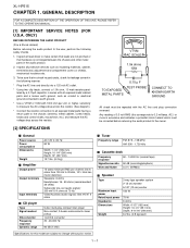
AXSMECeLuaHrdH-vrHkiAioPcePe5tP51M1T55aEnuRal1. VTVM AC SCALE
1.5k ohms 10W
TO EXPOSED METAL PARTS
0.15 µ F TEST PROBE
CONNECT TO KNOWN EARTH GROUND
All check must be corrected before returning the audio product to the owner.
[2] SPECIFICATIONS
I General
Power source Power consumption Dimensions
Weight
I Amplifier
Output power
Output terminals
Input...outlet.
* Using two clip ...
Service Manual - Page 3
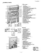
...13. Tape Button 24. Tuning Up Button 27. Disc Number Indicators 2. Daily Timer Indicator 13. Video/Auxiliary (Audio Signal) Input Jacks 8. Subwoofer Pre-output Jack
■ Speaker system
8
1. Speaker Wire
2
4
1 - 2 CD ... 8
9
21
23
22
24
1 2 34 5
67
14 15 16 17
1 2 3
XL-HP515
10 11 12 13 14 15 16 17 18 19 20
25 26 27
I Front panel
1. Clock/Timer Button 5.
Service Manual - Page 5
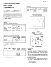
...ADJUSTMENT POINTS
3.
Each time a disc is changed, these adjustments are performed automatically. Input: Antenna Output: TP302 *2. Specified Value
3,000 ± 30 Hz
Instrument Connection
...Turn the core of each disc can be performed under optimum conditions.
ADJUSTMENTS
XL-HP515
[1] ADJUSTMENT
1. Input: Antenna Output: TP301 • FM RF
Signal generator: 1 kHz,...
Service Manual - Page 7
...= "RFLS_XX"
VOL - XL-HP515
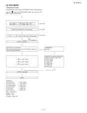
2 - 3 CD T EST
OPEN/CLOSE operation is input into PLAY key, track number...input.
[2] TEST MODE
• Setting the test mode During stand-by mode, press ON/STAND-BY button while pressing
down the
button and X-BASS/DEMO button.
Do normal play. then, press the CD
button to page 2-4
key input. Do TOC IL. FLAT
X-BASS - When these following key is using...
Service Manual - Page 8
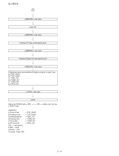
...key input.
Adjustment result automatically will display as below for each 2 sec : a) "FOF_XXXX" b) "TOF_XXXX" c) "TBAL_XX" d) "TGAN_XX" f) "FGAN_XX" g) "RFLS_XX"
key input. Laser ON.
Tracking ON play at that specific point. STOP
Sliding the PICKUP with>, > button must only be
2 - 4
key input.
XL-HP515
A
key input. Tracking OFF play from that specific point. key input...
Service Manual - Page 9
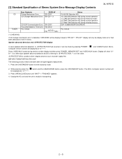
... is detected, 'CHECKING' will be display instead of Stereo System Error Message Display Contents
XL-HP515
CD TUNER
Error Contents
DISPLAY
Pickup Mechanism Error.
'ER-CD01'
CD Changer Mechanism Error....Press OPEN/CLOSE button until "WAIT"--> "FINISHED" appears.
4.
Press 'VIDEO/AUX' button during initialize process DSP COMMUNICATION ERROR. Display will
3.
Press the ON/...
Service Manual - Page 14
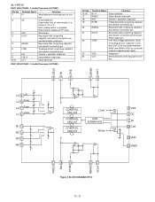
... REC R REC 16
11 12 15
JK690
L VIDEO/AUX L 9
R
R 16
TAPE L 10
R 15
TUNER L 11
R 14
CD L 12
R 13
DI 1
CE 2
IC601 CLK 24
LC75341
21 R
AUDIO PROCESSOR 4 L
13
+B5
P.B 4 L PB
21...
FM+B
Q360 FM
SWITCHING
FROM CD SECTION CNP2
CNS2
1 2 3
SWITCHING
REC /P.B.
XL-HP515
AXSMECeLuaHrdH-vrHkiAioPcePe5tP51M1T55aEnuRal4. REC/PLAY Q107 Q108 MUTING
ñ20dB ATT Q601
Q602
Q603 Q604
+...
Service Manual - Page 19
...by Digital Multimeter between such a section and the chassis with "
" (
) are used .
(CH), (TH), (RH), (UJ): Temperature compensation
(ML): Mylar type
(P.P.):... PRESET DOWN CD TUNER (BAND) VIDEO/AUX TAPE REC/PAUSE
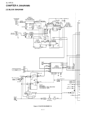
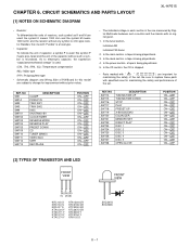
POSITION ON-OFF ON-...back. 5. CIRCUIT SCHEMATICS AND PARTS LAYOUT
[1] NOTES ON SCHEMATIC DIAGRAM
XL-HP515
• Resistor:
To differentiate the units of the capacitor without any...
Service Manual - Page 20
... GR
C621 1/50 11 L2
TUNER
R
C
BI601
CNS2 R-CH 1
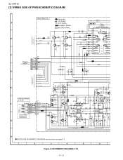
6-11 11 - XL-HP515
[3] WIRING SIDE OF PWB/SCHEMATIC DIAGRAM
MAIN PWB-A1(1/2)
FM SIGNAL
R601 1K
CD SIGNAL
R602 1K
C652 220P C651 220P
A
AUX SIGNAL
IC601
PLAYBACK SIGNAL
LC75341
RECORD SIGNAL
AUDIO PROCESSOR
1 DI
CL
R605 C609
2 CE
VD
-+
-+ -+
-+
R613
10K 1/50
3 VSS...
Service Manual - Page 27
... 3.9K 5.6K
10K
SW710 SW711 SW712 SW713 SW714 SW715 SW716 SW717
SW718
CD
TUNER
VIDEO /AUX
TAPE
(BAND)
RD01 RD02 RD03 RD04
680 820
1K 1.5K
SW701 SW702 SW703 SW704
TUNING .../ REVERSE REVERSE STANDBY TIMER/ MODE PLAY PRESET
DOWN
7
8
9
10
11
12
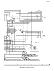
Figure 6-9 SCHEMATIC DIAGRAM (8/10) 6 - 9 XL-HP515
G6
P_IN AVREF AVDD
G6
+B
F1
F1
NP
NP
G1
G2
G3
G4
G5
09 8 7 6 5 4 3 2 1
...
Service Manual - Page 32
...
R78
B L BLUE V L VIOLET G Y GRAY W H ( W ) WHITE
SW719 X-BASS
/DEMO
246 SW716
1357 STOPCNP702
SW715 TUNING/ TIME DOWN
RD09 SW711 VIDEO/
AUX
D705 Q703
G
B K BLACK
PK
PINK
1
7
FFC702
DIS
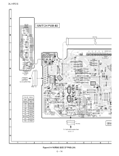
TO TAPE MECHANISM PWB 6-20 4 - XL-HP515
A
SW728 OPEN/ CROSE
SWITCH PWB-B2
B
RD25
SW727 DISC 5
SW726 DISC 4
RD24
RD23
SW725 DISC 3
1
FFC706
7
SW724
C
DISC 2
RD22...
Service Manual - Page 39
... CD lens cleaner should be caused by law. Cleaner disc
2. CD optical pickup Lens cleaner disc
Parts code UDSKA0004AFZZ
HOW TO USE
1.
If (1) and (2) are OK, check the system microcomputer (especially the communication line with the bare hand.
1. AXSMECeLuaHrdH.... Do not drink the cleaner fluid or allow it .
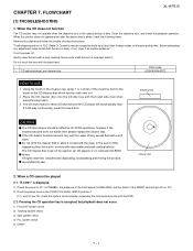
2. All rights reserved. FLOWCHART
XL-HP515
[1] TROUBLESHOOTING
1.
Service Manual - Page 42
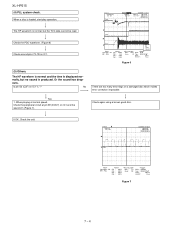
... V CH3 : 0.00 V CH4 : 0.00 V
=Record Length= Main : 1 K Zoom : 100
=Trigger=
Mode : NORMAL
Type : EDGE CH1
Delay :
2.887 ms
Hold off :
0.2 µs
Figure 6
(5) Others.
Check again using a known good disc.
XL-HP515
(4) PLL system check.
Service Manual - Page 43
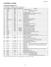
...-
Slice level Control output pin. RF signal input pin. A signal input pin.
E signal input pin.
F signal input pin.
D/A output.
Defect signal output pin.
External deiemphasis setting pin, INternal signal monitor pin 1.Controlled by command from the EFM sig-
Left channel L channel Power supply pin.
OTHERS
XL-HP515
[1] FUNCTION TABLE OF IC
IC1 VHiLC78648E...
Service Manual - Page 44
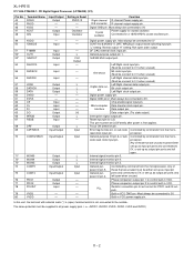
... power supply pins, i, e., AVDD1, AVDD2, XVDD, DVDD, LVDD and RVDD)
8 - 2 XL-HP515
IC1 VHiLC78648E-1: CD Digital Signal Processor (LC78648E) (2/2)
Pin No. 44 45 46 47 48
Terminal Name RCHO RVDD XVSS XOUT XIN
Input/Output Output - - Output Input
Setting in VCO.
DAC external clock input pin.
Built-in VCO. The same potential must be set...
Service Manual - Page 46
... channel 2 (for gain control) Input pin for channel 3 Input pin for channel 3 (for gain control) Input pin for channel 4 Input pin for channel 4 (for bridge. CH6 Output change pin (REV). Logic input for channel 4. BTL Output pin (+) for bridge. Logic input for channel 4. Reference voltage input pin. BTL Output pin (-) for bridge. XL-HP515
IC2 VHILA6261//-1: Focus/Tracking/Spin...
Service Manual - Page 48
... between VREF and AWSS (VSS) as a countermeasure against power ripple. Bass band filter comprising capacitor and resistor connection pin and bass/treble output pin. Input selector output pin.
XL-HP515
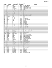
IC601 VHiLC75341/-1: Audio Processor (LC75341)
Pin No. 1 2
3 4
5 6 7 8 9-12
Terminal Name DI CE
VSS LOUT
LBASS LTRE LIN LSEL0 L4-1
Function Serial data and clock...
Service Manual - Page 49
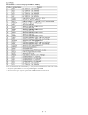
...Name VDD -20dBATT T BIAS T_REC/PLAY NO USE CD RESOUT CD_WRQ NO USE NO USE RESET XOUT XIN VPP NO USE CD_DRF VDD CLK DI DO CE CD CE ... Tape Run Pulse detect. Key input. Ground voltage. XL-HP515
8 - 7 Open. Tuner signal meter/Span Selecetor. Analog power supply 5V. Speaker abnormal detect. Input Input Input Input Input Input Input Input Input Input Input Input - Tape REC/PLAY control....
Service Manual - Page 50
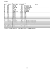
Illumination LED. Open. Open. FL segment driver. Open. FL segment driver/Destination input. FL segment driver/Destination input. Karaoke latch. Open. FL segment driver/Destination input. VLOAD -35V FL segment driver. Mic sw detect. Open.
Open. Open. XL-HP515
IC701 RH-iXA020AWZZ: System Microcomputer (IXA020AW) (2/2)
Pin No. 54 55 56 57 58* 59 60* 61* 62...
Similar Questions

Can The Sharp Cd-dh899n Mini Component System Be Adaptable To Bluetooth?
I was given a Sharp CD-DH899N Mini Component System. It has never been out of the box so I am wonder...
I was given a Sharp CD-DH899N Mini Component System. It has never been out of the box so I am wonder...
(Posted by scpenrod48 7 months ago)

Aux Input.
Hi there! My mother in law has a Sharp CD-E700 stereo system and wants to know how to connect her ph...
Hi there! My mother in law has a Sharp CD-E700 stereo system and wants to know how to connect her ph...
(Posted by Alyssatoppins 6 years ago)

May I Download A Free Operating Manual For The Sharp Xp-hp515?
(Posted by jesso549 10 years ago)

Setting Sharp Stereo Shelf System Xl Hp515 Remote Control
Please help me set my remote control channels for my Hl hp515
Please help me set my remote control channels for my Hl hp515
(Posted by Cigarman8 11 years ago)
Program Remote
I Forgot How To Preprogram My Remote For A Sharpxlhp515
I Forgot How To Preprogram My Remote For A Sharpxlhp515
(Posted by MO7657 11 years ago)