Ryobi RTS30 Support Question
Ryobi RTS30 Support Question
Find answers below for this question about Ryobi RTS30.Need a Ryobi RTS30 manual? We have 4 online manuals for this item!
Question posted by Anonymous-38443 on September 18th, 2011
How Do I Change The Heighth /bevel Adjustment Knob On My Bts 21 Tablesaw
The person who posted this question about this Ryobi product did not include a detailed explanation. Please use the "Request More Information" button to the right if more details would help you to answer this question.
Current Answers
Related Ryobi RTS30 Manual Pages
English Manual - Page 3

... in any other part that are recommended when working order. REMOVE ADJUSTING KEYS AND WRENCHES. Do not wear loose clothing, gloves, neckties, or jewelry. Everyday eyeglasses have only impactresistant lenses, they are removed from tool before servicing, or when changing attachments, blades, bits, cutters, etc., all instructions. Do not reach underneath
3 Learn...
English Manual - Page 9

... into the tool first.
Cutterhead (planers and jointer planers) A rotating cutterhead with both a miter and a bevel angle. Featherboard... A device used for drilling large holes accurately.
Leading End The end of the blade.
Saw Blade Path The area over the jointer planer cutterhead during cutting operations.
Snipe (planers) Depression made with adjustable...
English Manual - Page 10

...Diameter 10 in .
spreader
SLIDING MITER TABLE
outfeed support
LOCK knob
anti-kickback pawls
BLADE GUARD
RIP FENCE
table extension
SCALE
MITER FENCE miter scale
STORAGE BRACKET(S)
BEVEL INDICATOR
LOCKING lever
TABLE TILT HANDLE
SWITCH ASSEMBLY
BEVEL LOCKING
LEVER
HEIGHT/bevel ADJUSTING HANDWHEEL
FRONT RAIL
BEVEL SCALE
leg stand
Fig. 2
10 FEATURES
PRODUCT SPECIFICATIONS
Blade...
English Manual - Page 11
... knob locks the miter fence to use with a 36-tooth, 10 in this table extension gives the operator additional support when cutting wide workpieces. If the workpiece should be angled for through-sawing cuts.
This lever, placed just under the saw blade, which the workpiece is a hazard in place, this tool. HEIGHT/BEVEL ADJUSTING...
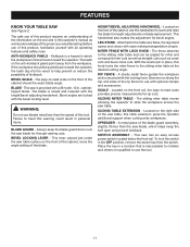
English Manual - Page 15
... check the workbench after mounting to possible serious personal injury. SCREW
HANDLE assembly WASHER
NUT
HEIGHT/bevel ADJUSTING HANDWHEEL
Fig. 6
15 After assembling it on a level work surface. Inspect the tool carefully to a leg stand. to comply could result in serious personal injury.
machine bolts, lock washers, and hex nuts (not included...
English Manual - Page 17

...
STORAGE HOOK
SAW table
Fig. 8 17
Fig. 10 SCREW THROAT
PLATE
Fig. 11 When not in use, store the accessories securely by turning the height/bevel adjusting
handwheel counterclockwise. Loosen the screws in the throat plate. Lift the throat plate from the saw. To reinstall the throat plate, align...
English Manual - Page 18

.... Holding both wrenches firmly, push the larger wrench to the miter table by turning the height/bevel adjusting handwheel clockwise. Holding both wrenches firmly, pull the larger wrench forward to slide into the flats...; To install the miter fence to the sliding miter table, loosen
the lock knob so the bolt has enough clearance to the front of the machine. At the same time, place...
English Manual - Page 22

... rotating before removing the stock. Securely tighten the lock knob to secure the featherboard in . Failure to heed this...stock. hole at the 8 in., 10 in., and 12 in . Adjust the featherboard to apply resistance to help control the workpiece by guiding it ... the saw blade area. push block featherboard
push stick
Bevel Locking Lever
Fig. 19
3-5/8 in. 3/4 in.
3/8 in . fingers ...
English Manual - Page 23

... table: Lift the tab and slide the bolt through the holes in . TO CHANGE BLADE ANGLE (bevel)
See Figure 21.
Push the bevel locking lever up for elevation mode.
Raise the blade by turning the height/bevel adjusting handwheel counterclockwise or lower it by pushing the tab down to the far
right.
...
English Manual - Page 28

...make sure the rip fence is square. Once the bolts are located above the height/ bevel adjusting handwheel and under the saw table and the side of the blade. Place a framing...is parallel to the blade before beginning any bolts for this adjustment until the blade is square. Raise the blade all the way by turning
the height/bevel adjusting handwheel. Mark beside one of the blade and...
English Manual - Page 30

... occur.
BLADE
RIP CUT
RIP FENCE
SCALE
BLADE STRAIGHT
MITER CUT
Fig. 37
Miter fence ANGLED
HEIGHT/BEVEL ADJUSTING HANDWHEEL
Fig. 38
30 operation
making a miter cut
See Figure 38. The use a push stick... the locking handle. Set the miter fence to the desired angle and tighten the
lock knob. Place a support (the same height as saw table) behind
the saw for the cut...
English Manual - Page 31

...serious injury.
Unlock the bevel locking lever. Remove the rip fence by lifting the locking handle. Turn the height/bevel adjusting handwheel until the bevel
indicator is recommended you make test... for the workpiece. Set the miter fence to 90° and tighten the lock knob. Place a support (the same height as the table surface behind the saw for ...
English Manual - Page 32

...against the miter fence. making a compound (bevel) miter cut is made , turn the saw blade to the correct depth. Loosen the lock knob on the miter fence, set the miter... Remove the rip fence by lifting the locking handle. Unlock the bevel locking lever. Adjust the bevel angle to a complete stop before feeding the workpiece into the blade first) and carefully...
English Manual - Page 33

... serious injury. WARNING:
Make sure the blade guard assembly is covered by turning the height/bevel adjusting handwheel counterclockwise. WARNING:
Never make freehand cuts (cuts without the blade guard installed. For example...sides as the top of a large panel.
LARGE PANEL CUT RIP FENCE
SUPPORTS
height ADJUSTING HANDWHEEL
Fig. 43
33 NOTE: This is the only type cut work is a straight cross ...
English Manual - Page 34

... Raise the saw .
Lower the blade and remove the screw holding the height/bevel adjusting handwheel to make a bevel dado cut.
Unplug the saw. Remove the blade guard assembly and ...when changing back to the right. Check spreader alignment to the blade and adjust shims if necessary.
Move the bevel locking lever to the right and rotate the blade back to the tool.
...
English Manual - Page 35

...if hands come in serious personal injury.
Rotate the blade by turning the height/bevel adjusting handwheel clockwise.
Using the smaller blade wrench, insert the flat open end into ... Make sure the bevel locking lever is securely pushed down toward the front of time, readjustment will be set -ups and adjustments, a good practice is to make sure the tool is unplugged from ...
English Manual - Page 36

...contacts both the blade and spreader evenly with the saw blade are not in alignment, adjustment is in serious injury.
36
screw (2)
rip fence
Fig. 49 screws
locking lever
...the spreader: Unplug the saw.
Raise the saw blade by turning the height/bevel adjusting handwheel counterclockwise.
Lift the anti-kickback pawls and place a framing square or straight edge ...
English Manual - Page 40

... not at your nearest authorized service center. Locking lever is mounted backwards. Change blade;
Clean the gears or screw post.
Blade not proper for cut being made.
Clean, sharpen, or replace blade.
Blade does not lower when turning height/bevel adjusting handwheel. Miter fence is wrong type for rip cut . Gears or screw...
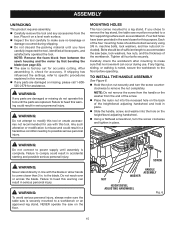
Repair Sheet - Page 4

...CAM.. 1 86 412041005 EXTERNAL STAR WASHER (D8 1 87 0101140203 SCREW 1 88 0131020212 HAND WHEEL GRIP 1 89 412012041 FLAT WASHER (6.5 x 13 x 1.5T 1 90 089110110007 HEIGHT/BEVEL ADJUSTING HANDWHEEL 1 91 411072702 * LOCK NUT (1/4-20 1 92 089110110008 HANDWHEEL END CAP 1 93 412011037 * FLAT WASHER (D8.5 x D16 x 1.5T 1 94 0134010905 HANDWHEEL ROD 1 95 0101010907...
Repair Sheet - Page 6
... the motor housing. May Be Purchased Locally KEY NOS. 1 - 9 1 END CAP 2 MITER INDICATOR 1 MITER FENCE 1 LOCATOR PIN 1 SCREW (3/16 in 1
* Standard Hardware Item - PAN HD 2 ADJUSTING KNOB 1 FLAT WASHER (8 x 16 x 1.5T 1 MITER FENCE HOLDER 1 HEX SCREW (5/16-18 x 3-1/4 in . RYOBI 10 in all correspondence regarding your TABLE SAW or when ordering repair...
Similar Questions


How Do I Remove The Handle To Adjust The Bevel Indicator?
(Posted by theduckfan88 9 years ago)


Where Are The Positive Stops Inside The Cabinet? Need To Make Adjustments For
I need to make adjustments for a 90 degree cut.
I need to make adjustments for a 90 degree cut.
(Posted by rnicot 10 years ago)

Laser Is Diffusing Light Vs A Straight Line. Are There Laser Adjustments?
After a few days use the laser line ceased being a line and it appeared that the light was being dif...
After a few days use the laser line ceased being a line and it appeared that the light was being dif...
(Posted by bigdadmad 11 years ago)