Icom IC-PW1 Support Question
Icom IC-PW1 Support Question
Find answers below for this question about Icom IC-PW1.Need a Icom IC-PW1 manual? We have 1 online manual for this item!
Question posted by rw3xw on January 11th, 2020
Ic-pw1 Swr Meter Fault
My IC-PW1 fails to indicate SWR. The output power is OK on all bands and tuner works properly. All reading are OK on SW-board: Po,Vd, TEMP, Id, ALC except for SWR. When attaching 75 OHm dummy load to the amplifier the signals on FOR & REF pins 7 & 8 of IC26 (TMP9038F) are 2 & 0.5 volts respectively, but SWR meter needle don't move at all.
Current Answers
Answer #1: Posted by waelsaidani1 on January 27th, 2020 8:46 AM
waelsaidani1

Member since:
May 12th, 2013 Points: 19,501,787

Member since:
May 12th, 2013 Points: 19,501,787
Possible cause:
Antenna SWR is more than 3:1. R26;The antenna tuner is turned OFF. R26;The linear amplifier is located in an area with bad air circulation. R26;[ALC adj] is not adjusted properly.
Check the antenna SWR. Adjust the antenna, if necessary. R26;Push [TUNER] to turn the antenna tuner ON. R26;Select a location with good air circulation. R26;Adjust [ALC adj] to the correct position.
Related Icom IC-PW1 Manual Pages
Instruction Manual - Page 1

INSTRUCTION MANUAL
HF/50 MHz ALL BAND 1 kW LINEAR AMPLIFIER
iPW1
Instruction Manual - Page 2
...
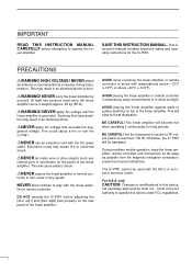
READ THIS INSTRUCTION MANUAL CAREFULLY before adjusting the [ALC adj1] and [ALC adj2] pots properly on top of the linear amplifier. ear amplifier. NEVER carry the linear amplifier by Icom Inc., could cause a fire or ruin the IC-PW1. RNEVER use an extension cord with the AH-2 HF AUTOMATIC ANTENNA TUNER...
Instruction Manual - Page 3
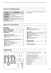
...10
3 OPERATION 11-14 s When first applying power (CPU resetting) ...... 11 s Setting the ALC levels 11 s Programming the CI-V address 12 s Operation 13 s Antenna tuner operation 14 s Protection circuit 14
4 MAINTENANCE 15 s Troubleshooting 15
5 SPECIFICATIONS 16
UNPACKING
q
w
e r t yu
i
o
!0
Accessories included with the IC-PW1:
Qty. CAUTION Equipment damage may occur. The...
Instruction Manual - Page 4
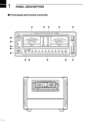
1 PANEL DESCRIPTION
s Front panel and remote controller
!5
!4 !3
!2
!1
HF/50MHz ALL BAND 1kW LINEAR AMPLIFIER
q w
POWER TRANSMIT
,
1P
8
*%
)05
"
5&.1
Po ID TEMP
VD SWR ALC
7%
483
"-$BE K
"-$
7
ʿ
1 2
INPUT
METER-1
METER-2
e
TUNER
1
r
2
AMP/ PROTECT
DOWN AUTO 1.8 3.5
7
10 14
18 21 24 28 50
UP
3 4
t
ANT
yu
i
o
!0
108...
Instruction Manual - Page 5
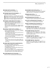
...'s voltage (VD), SWR (Standing Wave Ratio) or ALC (Automatic Level Control) level for transmit meter-2.
!4 TRANSMIT METER-1 [METER-1] Shows the RF output power (PO), final FET's current (ID) or heatsink temperature (TEMP).
!5 TRANSMIT METER-1 SELECTOR Selects the RF output power (PO), final FET's current (ID) or heatsink temperature (TEMP) for 2 sec. blinks while tuning. - Push [TUNER] for...
Instruction Manual - Page 6
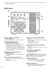
...] (pgs. 7-9) Used for band control with a PL-259 connector. RCAUTION!
Circuit breaker capacity: 20 A (U.S.A. w ACCESSORY SOCKET-1 [ACC-1] ACCESSORY SOCKET-2 [ACC-2] Enable connection to the ALC input jack of the remote controller and linear amplifier. u ALC LEVEL ADJUSTMENT POTS [ALC adj1]/[ALC adj2] (p. 11) Adjust the ALC levels. DO NOT operate the IC-PW1 be used for...
Instruction Manual - Page 7
... NAME
DESCRIPTION
SPECIFICATIONS
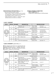
1
8 V
Regulated reference 8 V DC output Output voltage
from the [ACC-1] socket.
When [EXCITER] is connected. [ACC-2] outputs the received [ACC-1] signal to 8.0 V
5
ALC ALC voltage output.
Output current : Less than 1 A
4 Input voltage Input current
: 8 V ±0.3 V : Less than 200 mA
4
BAND
Band voltage input. (Varies with a PL-259...
Instruction Manual - Page 8
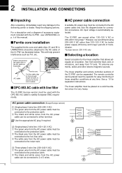
... controller sections of linear amplifier conditions at any damage to the protective earth. Keep the shipping cartons.
For a description and a diagram of this manual. ii of accessory equipment included with line filter
The IC-PW1 Europe version must be attached to satisfy European EMC requirements. s AC power cable connection
A suitable AC power plug must be...
Instruction Manual - Page 9
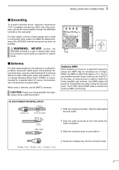
... ground as short as a well-matched 50 Ω antenna with output power and sensitivity.
ning by using 1 antenna, use the [ANT1] connector. The IC-PW1 has an SWR meter to a gas or electric pipe, since the connection could cause an explosion or electric shock.
s Antenna
For radio communications, the antenna is of critical importance, along with more...
Instruction Manual - Page 10
...power cable connection.
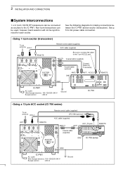
• Using 1 Icom exciter (transceiver)
To an antenna ACC-1
ANT
REMOTE
EXCITER
1
1&2
Remote control cable (supplied) ACC cable (supplied)
Be sure to connect the cable to the IC-PW1... the IC-PW1 and an exciter (transceiver). 2 INSTALLATION AND CONNECTIONS
s System interconnections
1 or 2 Icom 100 W HF transceivers can be used, however, band selection will...
Instruction Manual - Page 11
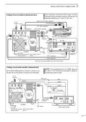
... a non-Icom exciter (transceiver)
Set the [EXCITER] switch to the 7-pin ACC(2) jack. To an antenna
ALC1
ANT
SEND1
RCA plug INPUT1
ALC SEND
SEND
EXCITER
1
1&2
Relay
DC power
GND
Coaxial cable (supplied)
IC-PW1
AC outlet
(Non-Europe versions : 100-120/220-240 V
Europe version
: 230 V)
Ground
RF OUT
GND DC OUT SEND...
Instruction Manual - Page 12
....
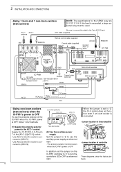
•Jumper location of linear amplifier
S3
J3
J4
2 1
• Jumper location of controller
12
These diagrams show the factory defaults.
9
nected to the 7-pin ACC(2) jack. to IC-PW1 [INPUT1] 13.8 V DC
[ACC-1]
to IC-PW1 [GND]
6
3
1
RF
GND
524
DC SEND ALC
IC-PW1 (DIN)
Non-Icom exciter
(2) Use the auxiliary power supply
Set the jumper to...
Instruction Manual - Page 13
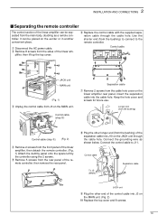
..., then detach the remote controller. (Fig. 1) Attach the dummy panel onto the space left by the controller using ...can be separated from the cable hole cover on the linear amplifier rear panel. plifier, then lift up the ... cable with the supplied separation cable through the cable hole. q Disconnect the AC power cable. Use the shorter end (from the bushing) of the remote controller, then...
Instruction Manual - Page 14
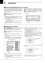
...1.5K
Po
0 10 20 30 40 50 60
W
ID
HOT
A
TEMP
METER-1
Output power
!1 Adjust the [ALC adj2] pot in the same manner when a 2nd exciter is complete. i While adjusting the 1st exciter's RF output power,
transmit a 100 W output power of 1.5:1 or better. Select a band which has an SWR of the selected band signal using the following procedure. Then, reset the linear amplifier using CW...
Instruction Manual - Page 15
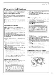
.... When using different baud rates (i.e. 4800 and 9600 bps, etc.), the exciters' frequencies are connected, turn the IC-PW1 power OFF
and complete the setting.
POWER TRANSMIT
HF/50MHz ALL BAND 1kW LINEAR AMPLIFIER iPW1
Po ID TEMP
VD SWR ALC
TUNER
METER-1
METER-2
AMP/
DOWN AUTO 1.8 3.5
7
10
14
18
21
24
28
50
UP
PROTECT
z x INPUT
z x c v ANT
12
w Rotate the...
Instruction Manual - Page 16
...Operation
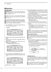
CAUTION:
DO NOT operate the IC-PW1 before turning the IC-PW1 and other transceiver power ON and keep the IC-781 power ON during split operation.
!0 When operating for long periods, select the temperature meter with minimum output power.
POWER TRANSMIT
HF/50MHz ALL BAND 1kW LINEAR AMPLIFIER iPW1
Po ID TEMP
VD SWR ALC
TUNER
METER-1
METER-2
AMP/
DOWN AUTO 1.8 3.5
7
10
14
18...
Instruction Manual - Page 17
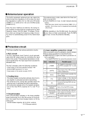
...automatically preset to the memorized point.
cuit is activated, a band indicator blinks to show a problem as a preset point for 50 MHz bands (VSWR 2.5:1). Item 1 2 3 4 5
Indication [TEMP] [AUTO] [ALC] [VD] [ID]
Possible cause
The heatsink temperature of the exciter.
Antenna SWR becomes 2:1 or more .
Once the tuner matches an antenna, the tuning circuit condition is activated and...
Instruction Manual - Page 18
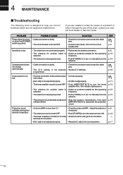
....
Adjust the antenna, if necessary. • Push [TUNER] to turn the antenna tuner ON. • Select a location with bad air circulation. • [ALC adj] is not adjusted properly.
• Check the antenna SWR.
If you correct problems which are unable to manually tune the antenna. pgs. 7-9
p. 12
Output power is too low.
• Reverse connection on when...
Instruction Manual - Page 19
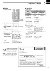
... power
: 100 W max.
• Spurious emissions : -60 dB (HF bands) -70 dB (50 MHz band)
• SEND connector : Phono (RCA)
• ALC connector
: Phono (RCA)
s Antenna tuner
• Matching impedance range:
HF bands*2
16.7 to 150 Ω unbalanced
(Less than VSWR 3:1)
50 MHz band
20 to 125 Ω unbalanced
(Less than 1.0 dB (after tuning)
Versions of the IC-PW1...
Similar Questions

Band Switching Failed
PW1 is on160m. I switch (per hand) to 80m. After pusching PPT, PW1 goes to failure. Switching now to...
PW1 is on160m. I switch (per hand) to 80m. After pusching PPT, PW1 goes to failure. Switching now to...
(Posted by setcomcast 7 months ago)

Ic7410 Monitor Inaudible
The monitor on my IC7410 does not seem to work on SSB. I get plenty of sidetone on CW, but cannot he...
The monitor on my IC7410 does not seem to work on SSB. I get plenty of sidetone on CW, but cannot he...
(Posted by michaelagburch 10 months ago)

Mauque Manifeste De Puissance 0 Mon Trasceiver Iv 7200
Sur charge fictive en CW l'appareil délivre seulement 50 W au lieu de 100 et l'indicateur ALC m...
Sur charge fictive en CW l'appareil délivre seulement 50 W au lieu de 100 et l'indicateur ALC m...
(Posted by baudauxguy 1 year ago)

Icom 7600 Rf Power Problem
Hi I have a ICOM IC 7600 with a output power problem will work for 5mins on full then drops to 7wats...
Hi I have a ICOM IC 7600 with a output power problem will work for 5mins on full then drops to 7wats...
(Posted by Anonymous-162979 6 years ago)

Over-current Shut Down On 2m And 432mhz.
My IC-9100 is only 8 months old and has not seen a lot of use. Yesterday I was on 2M FM when the pow...
My IC-9100 is only 8 months old and has not seen a lot of use. Yesterday I was on 2M FM when the pow...
(Posted by kentteri 7 years ago)