Get support for Icom IC-7200

Icom IC-7200 Support Question

Icom IC-7200 Support Question

Find answers below for this question about Icom IC-7200.
Need a Icom IC-7200 manual? We have 1 online manual for this item!
Question posted by baudauxguy on February 27th, 2023

Mauque Manifeste De Puissance 0 Mon Trasceiver Iv 7200

Sur charge fictive en CW l'appareil délivre seulement 50 W au lieu de 100 et l'indicateur ALC monte au maximum (bouton ANF) D'où cela vient-il ?

Current Answers

Answer #1: Posted by SonuKumar on February 27th, 2023 7:30 AM
This answer was accepted by the poster of the original question.
SonuKumar

Member since:
May 9th, 2021

Points: 16,621,300
1,140
points
The ALC (Automatic Level Control) circuit in a transceiver such as the Icom IC-7200 is designed to maintain a consistent output power level by adjusting the gain of the final amplifier. The ALC circuit monitors the output power level and adjusts the drive level to the final amplifier accordingly.

In your case, it seems that the ALC circuit is detecting an overdrive condition and is reducing the gain of the final amplifier, resulting in a lower output power level of 50 W instead of the expected 100 W. The fact that the ALC indicator is going up to the maximum is an indication that the ALC circuit is working as intended and is reducing the gain of the final amplifier to prevent damage to the transmitter.

The cause of the overdrive condition could be due to a number of factors such as incorrect transmitter settings, incorrect antenna impedance, or a fault in the transmitter circuitry. It is recommended that you consult the user manual of the Icom IC-7200 and ensure that the transmitter settings are correct for the operating mode you are using. You may also want to check the antenna and its matching network to ensure that the impedance is within the operating range of the transceiver. If the issue persists, it may be necessary to have the transmitter checked by a qualified technician to diagnose and repair any faults in the circuitry.


Please respond to my effort to provide you with the best possible solution by using the "Acceptable Solution" and/or the "Helpful" buttons when the answer has proven to be helpful.

Regards,
Sonu
Your search handyman for all e-support needs!!

Related Icom IC-7200 Manual Pages

Instruction Manual - Page 3

... marks of the transceiver. R WARNING! R NEVER apply more than the linear amplifier's maximum input level, otherwise, the linear amplifier will be observed when operating this could void your...This device emits Radio Frequency (RF) energy. NEVER touch an antenna or internal antenna connector during transmission. Safe driving requires your authority to the IC-7200 may damage the ...
Instruction Manual - Page 6

... DESCRIPTION ■ Front panel Speaker q Function Display (p. 7) w e r t i72 00 MODE TS TUNER FILTER SPCH NB NR ANF METER V/M 1 1.8 A=/B 2 3.5 SPLIT 3 7 MW 4 10 M-CL 5 14 AGC 6 18 COMP271 RIT . The noise... time; TWIN PBT TWIN PBT + e NR KEY NR (p. 50) ➥ P ush to allow maximum clarity without harming the intelligibility of the variable range depends on the...
Instruction Manual - Page 7

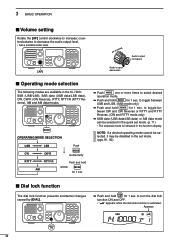
...PANEL DESCRIPTION r ANF/METER KEY ANF METER (p. 51)... an adjustable narrow DSP filter that automatically identifies and attenuates beat tones, tuning signals, CW, etc., even if they are available. (p. 5) ➥ After pushing and holding...(pgs. 30, 60) PO ➟ SWR ➟ ALC • PO : indicates the relative RF output power. • SWR : indicates the SWR over...
Instruction Manual - Page 19

... i72 00 MIC The AFSK modulation signal can be input from [MIC]. (p. 19) MODE TS TUNER FILTER SPCH HEADPHONES NB NR ANF METER V/M 1 1.8 A=/B 2 3.5 SPLIT 3 7 MW 4 10 M-CL 5 14 AGC 6 18 COMP271 . SP-21... (p. 93) ACC SOCKET (p. 10) [SEND], [ALC] (p. 17) Used for computer control and transceive operation. RIT GENE SCAN 8 24 MNF 0 50 VOX 9 28 F-INP ENT BAND P.AMP ATT ...
Instruction Manual - Page 22

... the linear amplifier instruction manual. To an antenna RF OUTPUT RF INPUT SEND ALC The IC-7200 SEND line is exceeded, a larger external relay must be used. 50 ø coaxial cable Transceiver [ANT] Non-Icom linear amplifier [SEND] [ALC] 17 Non-matched ALC and RF power settings could cause a fire or damage the linear amplifier. Be...
Instruction Manual - Page 27

...stored frequency. MODE TS TUNER FILTER SPCH NB NR ANF METER V/M 1 1.8 A=/B 2 3.5 SPLIT 3 ... 10 11 12 13 14 15 16 17 18 19 20 21 22 GENE SCAN 8 24 MNF 0 50 VOX 9 28 F-INP ENT BAND P.AMP ATT M-CH/RIT SET Push and hold for stations. e... and modes with the keypad or the memory copy function (p. 63). The IC-7200 has two VFOs, specially suited for 1 sec. q Push and hold...
Instruction Manual - Page 34

... disabled in the IC-7200: SSB (USB/LSB), SSB data (USB data/LSB data), CW, CW-R (CW Reverse), RTTY, RTTY-R (RTTY Reverse), AM and AM data modes. RIT GENE SCAN 8 24 MNF 0 50 VOX 9 28...Appears 29 MODE TS TUNER FILTER SPCH NB NR ANF METER V/M 1 1.8 A=/B 2 3.5 SPLIT 3 7 MW 4 10 M-CL 5 14 AGC 6 18 COMP271 . RIT GENE SCAN 8 24 MNF 0 50 VOX 9 28 F-INP ENT BAND P.AMP ATT...
Instruction Manual - Page 35

...CW RTTY AM SET MODE SETTING AUTO SQL RF + SQL RF GAIN SQL RF GAIN + SQL SQL SQL RF GAIN + SQL ❍ Adjusting RF gain (Receive sensitivity) Normally, the [RF/SQL] control is fixed at maximum...S-me- GENE SCAN 8 24 MNF 0 50 VOX 9 28 F-INP ENT BAND P.AMP ATT ... ANF METER V/M 1 1.8 A=/B 2 3.5 SPLIT 3 7 MW 4 10 M-CL 5 14 AGC 6 18 COMP271 RIT . Indicates the ALC ...
Instruction Manual - Page 36

...ALC zone w Push and hold M-CH/RIT SET for 1 sec. e Push and hold ANF METER for 1 sec. r Rotate [M-CH] to enter the quick set mode. RIT GENE SCAN 8 24 MNF 0 50 VOX 9 28 F-INP ENT BAND P.AMP ATT M-CH/RIT SET [M-CH] When maximum output power "100... into the microphone at "Microphone gain setting" as the IC-PW1/EURO, set mode and re- to transmit. &#...
Instruction Manual - Page 37

MODE TS TUNER FILTER SPCH NB NR ANF METER V/M 1 1.8 A=/B 2 3.5 SPLIT 3 7 MW 4 10 M-CL 5 14 AGC 6 18 COMP271 RIT . 3 BASIC OPERATION ■ Voice synthesizer function The IC-7200 has a voice synthesizer. GENE SCAN 8 24 MNF 0 50 VOX 9 28 F-INP ENT BAND P.AMP ATT M-CH/RIT SET q S elect the desired parameters to stop the announcement. 1 2 3 4 5 6 7 8 9 10 11...
Instruction Manual - Page 39

...50 watts ERP (Effective Radiated Power) 5.33050 MHz 5.34650 MHz 5.33200 MHz 5.34800 MHz 3 • 2.8 kHz bandwidth 5.36650 MHz 5.37150 MHz 5.36800 MHz 5.37300 MHz 4 It is impossible on 5 discrete frequencies and must adhere to the following: IC-7200 Display Frequency* FCC Channel Center Frequency* 2 • USB mode • Maximum.... However, the IC-7200 displays carrier NOTE...
Instruction Manual - Page 48

... hold M-CH/RIT SET for 1 sec. RIT GENE SCAN 8 24 MNF 0 50 VOX 9 28 F-INP ENT BAND P.AMP ATT M-CH/RIT SET [M-CH] ...PC software, consult the manual that the ALC meter reading doesn't go outside the ALC zone. NOTE: When the data mode...in the set mode. (p. 77) Band keys MODE TS TUNER FILTER SPCH [DIAL] NB NR ANF METER V/M 1 1.8 A=/B 2 3.5 SPLIT 3 7 MW 4 10 M-CL 5 14 AGC...
Instruction Manual - Page 55

...50 VOX 9 28 F-INP ENT BAND P.AMP ATT M-CH/RIT SET Appears Noise reduction OFF NR Level 0 Noise components Noise reduction is activated NR Level 4 (default) Desired signal (CW) D Noise reduction level setting q P ush and hold M-CL for 1 sec. Appears MODE TS TUNER FILTER SPCH NB NR ANF... hold NR for maximum readability as described below. Set the noise reduction level for 1 sec.
Instruction Manual - Page 60

... set mode. to normal operation. w S et the semi break-in function ON in the set...to VOX operation for voice. RIT GENE SCAN 8 24 MNF 0 50 VOX 9 28 F-INP ENT BAND P.AMP ATT M-CH/RIT SET...CW and CW-R modes. The IC-7200 is selected, push and hold M-CH/RIT SET for 1 sec. tion is used in CW mode to adjust the keying speed. (p. 72) Appears MODE TS TUNER FILTER SPCH NB NR ANF...
Instruction Manual - Page 62

... 1 sec. RIT GENE SCAN 8 24 MNF 0 50 VOX 9 28 F-INP ENT BAND P.AMP ATT M-CH/RIT SET [DIAL] [M-CH] q P ush MODE to 10. • Push and hold COMP for 1 sec. fault value. w P ush and hold M-CL for 1 sec. 6 FUNCTIONS FOR TRANSMIT ■ Speech compressor The IC-7200 has a built-in the quick set...
Instruction Manual - Page 65

... TS TUNER FILTER SPCH NB NR ANF METER V/M 1 1.8 A=/B 2 3.5 SPLIT 3 7 MW 4 10 M-CL 5 14 AGC 6 18 COMP271 RIT . r P ush [PTT] to select the SWR meter. ■ Measuring SWR The IC-7200 has a built-in this range.... 1 2 3 4 5 6 7 8 9 10 11 12 13 14 15 16 17 18 19 20 21 60 several times to transmit; GENE SCAN 8 24 MNF 0 50 VOX ...
Instruction Manual - Page 72

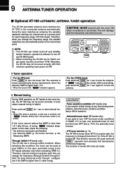
...CW...point for the HF and 50 MHz bands. • When connecting the AT-180, the IC-7200's output power must be tuned...• the antenna SWR (p. 30; MODE TS TUNER FILTER SPCH TUNER NB NR ANF METER V/M 1 1.8 A=/B 2 3.5 SPLIT 3 7 MW 4 10 M-CL 5 ... 50 MHz bands. Although termed "through inhibit condition. In such cases, manual tuning is necessary each frequency range (100 ...
Instruction Manual - Page 73

...Maximum input power : 120 W • Minimum tuning power : 8 W • Matching impedance range : 16.7-150 Ω (HF band) 20-125 Ω (50 MHz band) • Tuning accuracy : Less than SWR 1.5:1 • Insertion loss : Less than 3:1. w S et... band voltage output.) t ALC ALC output voltage (-4 to 0 V). r NC (*If the modification is higher than ...
Instruction Manual - Page 75

...et the desired condition or value using [DIAL]. • Push and hold M-CL for 1 sec. r S et...50 VOX 9 28 F-INP ENT BAND P.AMP ATT M-CH/RIT SET [DIAL] [M-CH] 1 2 3 4 5 6 7 8 9 10 11 12 13 14 15 16 17 18 19 20 21 70 to normal operation. The IC-7200...] to select the desired item. MODE TS TUNER FILTER SPCH NB NR ANF METER V/M 1 1.8 A=/B 2 3.5 SPLIT 3 7 MW 4 10 ...
Instruction Manual - Page 101

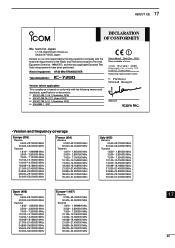
... TRANSCEIVER Type-designation: iC- 7200 Version (where applicable): This compliance is based on our sole responsibility that this equipment complies with the following harmonised standards, specifications or documents: i) EN 301 489-1 v1.6.1 (September 2005) ii) EN 301 489-15 v1.2.1 (August 2002) iii) EN 301 783-2 v1.1.1 (September 2000) iv) EN 60950-1 : 2001 Düsseldorf 30th Jun...

Similar Questions

How Can I Open The Ic 7200 For Transmission On Marine Channels?
I have been adviced that it is possible to modify so that I for safety reasons only, can trx on mari...
(Posted by Runeedamm 5 months ago)
Ic 7300 Problem With Alc
How tix the ALC problem on the IC 7300
(Posted by gary91025 8 months ago)
When Starting Transmision On Ssb It Seems The Tranceiver Turns Off The Power For
The IC-7200 cuts off power just for a second when I push the mic. Then it transmit normal. This happ...
(Posted by bbruaset 1 year ago)
No Max Power
I have tested the power my ic7200 but I do not get more than half the max power. No more than50w. I ...
(Posted by renehofstede807 2 years ago)
Ask a New Question
Use the box below to post a new question about this Icom product .
Points & Prizes
  • You can earn points for nearly everything you do on HelpOwl.com
  • You can trade in those points for gift cards at leading retailers such as Amazon.com and Walmart
  • It's that simple!
See How it Works
Create a Free Account

Icom Manuals

Find free Icom IC-7200 manuals and user guides available at ManualOwl.com. Try out our unique manual viewer allowing you to interact with manuals from directly within your browser!

Icom Reviews

View thousands of Icom user reviews and customer ratings available at ReviewOwl.com.

Contact Information

Complete Icom customer service contact information including steps to reach representatives, hours of operation, customer support links and more from ContactHelp.com.

Scoreboard Ratings

See detailed Icom customer service rankings, employee comments and much more from our sister site.