Icom IC-7410 Support Question
Icom IC-7410 Support Question
Find answers below for this question about Icom IC-7410.Need a Icom IC-7410 manual? We have 2 online manuals for this item!
Question posted by johnmatthew3 on July 18th, 2018
Icom 7410
What year was my icom 7410 manufactured, serial number 04001434, and what issues could i expect to have with it ? regards John.
Current Answers
Related Icom IC-7410 Manual Pages
Instruction Manual - Page 2
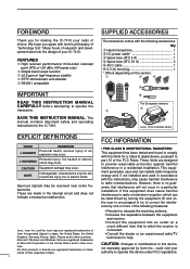
...and on, the user is encouraged to try to correct the interference by Icom Inc., could void your IC-7410. NOTE
If disregarded, inconvenience only.
These are made in Japan, the ...of
connected.
This
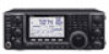
manual contains important safety and operating instructions for making the IC-7410 your radio of high frequency stability ❍ RTTY demodulator and decoder ❍ RS-...
Instruction Manual - Page 3

...
DC to the transceiver.
This may result in your Icom dealer or distributor for advice. This could cause a fire... above +50°C (+122°F). ally desire to the IC-7410 may overheat the transceiver.
The rear panel will damage the transceiver... actu- BE CAREFUL! USE only the specified microphone. Other manufacturers' microphones have different pin assignments, and connection to transmit....
Instruction Manual - Page 15
...[ACC]
13
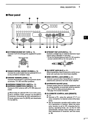
t ANTENNA CONNECTOR 2 [ANT2] (p. 16) Connect a 50 ø antenna with another Icom
16 17 18
CI-V transceiver or receiver.
u ALC INPUT JACK [ALC] (p. 21) When transmitting, ... control an
12
cal shocks, TVI, BCI and other
20
Icom transceivers or receivers, and vice versa.
(p. 89)
21
8
on the IC-7410
automatically changes those settings on the front panel. (p. 1) (+)...
Instruction Manual - Page 22
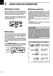
...base of Voltage Standing Wave Ratio (VSWR) on your operating preference.
■ Antenna connection
For radio communications, the antenna is higher than approx. 2.0:1, the transceiver automatically reduces the TX power to... distance between the [GND] terminal and ground as short as
shown at left. The IC-7410 has an SWR meter to a long ground rod. PL-259 CONNECTOR INSTALLATION EXAMPLE
q
30...
Instruction Manual - Page 28
...
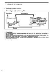
■ Linear amplifier connections (Continued)
D Connecting a non-Icom linear amplifier
To an antenna
50 ø coaxial cable
RF OUTPUT RF INPUT
GND
ALC SEND
Non-Icom linear amplifier
Ground
[ANT1]
Transceiver
[GND]
[ALC] [SEND... amplifier instruction manual.
• T he IC-7410 SEND terminal (ACC connector pin 3) is exceeded, a larger external relay must be used.
21
Instruction Manual - Page 31

... 20 21
24 You can be used for stations, push [A/B] again
to show the stored data on the undis-
played VFO. ■ VFO description
The IC-7410 has two VFOs;
r To continue searching for quick memory storage. VFO is selected. w Continue searching for quickly selecting two frequencies, or split frequency operation. CONVENIENT...
Instruction Manual - Page 38

... clockwise to increase the audio output level, counterclockwise to decrease it.
You can mute the microphone signals, depending on the "DATA MOD" setting in the IC-7410 are listed to the right for 1 second
Decreases
[AF]
31 See the diagram to the right.
Instruction Manual - Page 40
... after the frequency. * The S-meter level announcement can be announced in % (percent). • ALC : Displays the ALC level.
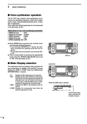
3 BASIC OPERATION
■ Voice synthesizer operation
The IC-7410 has a built-in voice synthesizer to announce the operating frequency, mode and S-meter level in clear, electronically-generated voice, in receive.
33 First, select the...
Instruction Manual - Page 61
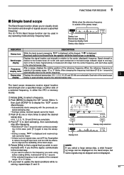
...receiving, repeat steps e and r. t R otate [DIAL] to find the signal, communicate in the normal way. • If you want to the center frequency. After a sweep, displays the relative position of the ... step, a wide frequency range can be used in either the VFO or memory modes. The IC-7410's Band Scope function can be displayed on either side of a selected frequency, in any operating ...
Instruction Manual - Page 65

D 1st IF filter selection
(Mode: SSB/CW/RTTY/AM) The IC-7410 has a 15 kHz filter passband width at the 1st IF frequency.
e P ush [F-5] once or twice to display the "FIL" screen (Filter).
w Select the SSB or ...
Instruction Manual - Page 66

... steps in the SSB/CW/RTTY modes, and 100 Hz in the FM mode. • W hile rotating the [TWIN-PBT] controls, noise may occur. The IC-7410 uses DSP for 1 second to the center position. • The "dot" disappears. Moving both [TWIN-PBT] controls shift the IF passband center frequency both above...
Instruction Manual - Page 75
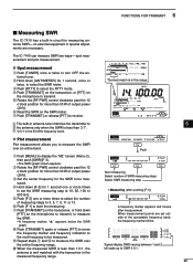
...Push [TRANSMIT] or release [PTT] to be measured.
t P ush [F-3] one or more times to select the number of measuring steps to 3, 5, 7, 9, 11 or 13.
i P ush [TRANSMIT] again or release [PTT... hold down [ANT•METER] for 1 second one or more times to transmit. The IC-7410 can measure SWR two ways- w R otate the [RF PWR] control clockwise past the 12
o'clock position for more...
Instruction Manual - Page 96

...
(Default: 80h)
To distinguish equipment, each CI-V transceiver has its own Icom standard address in 1% steps. The IC-7410's address is 01h to send RTTY de- the range is 80h.
See ... to an optional CT-17 ci-v level converter, rotate [DIAL] to the squelch state. USB Serial Func
(Default: CI-V)
Select the function for calibration procedure. Calibration Marker
(Default: OFF)
Use ...
Instruction Manual - Page 101
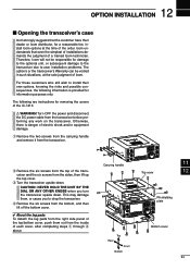
...The option's or the transceiver's Warranty can be responsible for removing the covers of the IC-7410. Therefore, Icom will not be voided in such situations, at the time of the order.
Carrying handle...12
13
14
PA shielding
15
plate
16
17
18
Bottom cover
19
20
21
94
Icom understands that the customer have their own options, knowing the risks and possible consequences, the...
Instruction Manual - Page 105
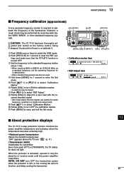
...adjust for 14.999.00 MHz. • Other standard frequencies can also be used.
CAUTION: The IC-7410 has been thoroughly adjusted and tested at 15.000.00 MHz) as
a standard frequency, set - tings... sure that two signals are exactly the same frequency, resulting in only the stand-by receiving radio station WWV, WWVH, or other standard frequency signals. i R otate [DIAL] to turn OFF...
Instruction Manual - Page 108

The Icom Communications Interface-V (CI-V) controls the transceiver. D Data format
The CI-V system can be operated using the Set mode.
9−15V DC RS-232C cable
PC
ct-17
IC-7410
mini-plug cable
When the...89 for frequency, memory number entry (see the data content description) End of message code (fixed)
(fixed)
FE FE E0 80 Cn Sc Data area FD
q
w ert
y
u
IC-7410 to controller
FE FE ...
Instruction Manual - Page 120
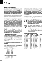
...of almost every gain antenna today. Versions of the IC-7410 which can be beneath the antenna array and have been... national licensing requirement.
• List of the European Radio and Telecommunication Terminal Directive 1999/5/EC. Be sure to ... 65 m
In all cases any possible risk depends on the serial number label, comply with the essential requirements of Country codes (ISO 3166...
Instruction Manual - Page 121
... Japan
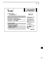
Declare on conformity with the essential requirements of issue
Icom (Europe) GmbH
Communication Equipment Auf der Krautweide 24, ...Kind of equipment: HF/50 MHz TRANSCEIVER
Type-designation: iC- 7410
Version (where applicable): This compliance is based on our ...Soden 14th Jan. 2011 Place and date of the Radio and Telecommunications Terminal Equipment Directive, 1999/5/EC, and that any...
Instruction Manual - Page 124

...LV LT LU MT NL PL PT SK SI ES SE GB IS LI NO CH BG RO TR HR
IC-7410 #04 (Europe-1)
< Intended Country of Use >
AT BE CY CZ DK EE FI FR DE GR ...LV LT LU MT NL PL PT SK SI ES SE GB IS LI NO CH BG RO TR HR
IC-7410 #11 (France)
< Intended Country of Use >
AT BE CY CZ DK EE FI FR DE GR... BG RO TR HR
A-6904H-1EX Printed in Japan © 2011 Icom Inc.
1-1-32 Kamiminami, Hirano-ku, Osaka 547-0003, Japan
Service Manual - Page 2
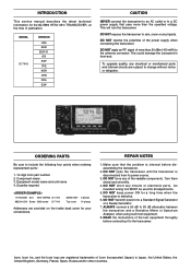
...1110003491 S.IC TA31136FNG IC-7410 8820001210 Screw 2438 screw IC-7410
MAIN UNIT 5 pieces Top cover 10 pieces
Addresses are registered trademarks of publication. Icom, Icom Inc. MODEL IC-7410
VERSION
USA...dB to include the following four points when ordering replacement parts:
1. 10-digit Icom part number 2.
To upgrade quality, any liquids.
DO NOT keep power ON for all ...
Similar Questions

Ic7410 Monitor Inaudible
The monitor on my IC7410 does not seem to work on SSB. I get plenty of sidetone on CW, but cannot he...
The monitor on my IC7410 does not seem to work on SSB. I get plenty of sidetone on CW, but cannot he...
(Posted by michaelagburch 11 months ago)

Icom8410 Folding Back Power
icom7410 folding back power could ot be rf alc circuit. Have order new caps on 741p but a antennas s...
icom7410 folding back power could ot be rf alc circuit. Have order new caps on 741p but a antennas s...
(Posted by andythebrave 1 year ago)

Serial Number
1001062 is my serial number....how can i find out the age of my radio...regards...
1001062 is my serial number....how can i find out the age of my radio...regards...
(Posted by mi0jbt 2 years ago)


Icom Ic-7000 Serial Numbers
Does the serial number indicate year of manufacture on the Icom IC-7000?
Does the serial number indicate year of manufacture on the Icom IC-7000?
(Posted by Anonymous-163051 6 years ago)