Dell OptiPlex GX200 Support Question
Dell OptiPlex GX200 Support Question
Find answers below for this question about Dell OptiPlex GX200.Need a Dell OptiPlex GX200 manual? We have 1 online manual for this item!
Question posted by yittae on October 29th, 2012
Local Area Connection
The person who posted this question about this Dell product did not include a detailed explanation. Please use the "Request More Information" button to the right if more details would help you to answer this question.
Current Answers
Answer #1: Posted by RathishC on October 29th, 2012 3:21 PM
RathishC

Member since:
June 19th, 2012 Points: 2,516,090

Member since:
June 19th, 2012 Points: 2,516,090
Hi,
Rathish C
#iworkfordell
Would request you to please elaborate on the issue you are facing, so that I can help you further. You can refer to the link below which will give you step by step information about wired internet connectivity:
http://dell.to/PbereC
You can refer the Dell Article 266237 on www.support.dell.com
Once you click the link, it will first ask you to select the Operating System which you are using and follow the steps which should resolve the issue.
Please reply if you have any further questions
Thanks & RegardsRathish C
#iworkfordell
Related Dell OptiPlex GX200 Manual Pages
Service Manual - Page 1
... Cautions Throughout this guide, blocks of text may result in this text: Dell and OptiPlex are used as follows:
NOTE: A NOTE indicates important information that helps you how to...other than its own. Initial release: 18 April 2000 Last revised: 31 Jul 2000 Dell™ OptiPlex™ GX200 Service Manual
Small Form-Factor Chassis - Removing and Replacing Parts Low-Profile Chassis -
NOTICE: A...
Service Manual - Page 2
... to avoid Removing and Replacing Parts: Dell™ OptiPlex™ GX200 Systems Service Manual
Overview Recommended Tools Precautionary Measures Internal...-head screwdrivers l 1/4-inch nut driver Also, use a wrist grounding strap as explained in the Dell OptiPlex low-profile chassis GX200 system. Doing so reduces the potential for your personal safety and to prevent damage to the system from...
Service Manual - Page 8
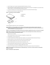
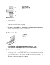
...place the drive/bracket on the side opposite the screw) clear the floor
divider (see Figure 10). Connect a power cable to the 40-pin interface connector on a surface, such as a foam pad, ...a flat surface with the bracket mounting holes facing up . 5. Position the bracket over the slots. 6. Connect one of the hard-disk drive. 2. Remove the four screws that it .
1. NOTICE: To avoid ...
Service Manual - Page 9
Partition and logically format your drive before you just installed is not already connected, connect the blue connector on the EIDE interface cable to the documentation that came with your system.
10.
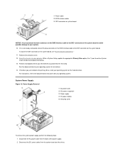
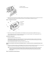
System Power Supply Figure 13. If it is ...
Service Manual - Page 10
Slide the power supply toward the front of the chassis. 4. Examine any cables connected to expansion cards through the back-panel openings and disconnect any cables you removed in "Precautionary Measures."
2. Slide the expansion-card cage out of the ...
Service Manual - Page 12
... Board Jumpers Figure 18 shows the location of the jumpers on a circuit board with two or more pins emerging from them. Figure 18. The wire connects the pins and creates a circuit. Otherwise, damage to your system is turned off its pin(s) and carefully fit it down over the pins. NOTICE: Make...
Service Manual - Page 13
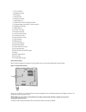
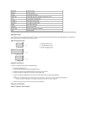
... PCI expansion-card connector Main power input connector 3.3-V power input connector Riser board connector Serial port connector Primary microprocessor connector USB connectors
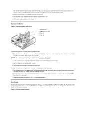
Expansion Cards
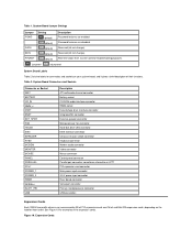
Each GX200 low-profile chassis can accommodate 32-bit PCI expansion cards and 16-bit and 8-bit ISA expansion cards, depending on your system board, and it...
Service Manual - Page 14
...you intend to maintain Federal Communications Commission (FCC) certification of the card you are connected. See the documentation that covers the card-slot opening . Save the screw to...3. The brackets also keep dust and dirt out of its electrical outlet before installing any cables connected to use (see Figure 21). Filler Bracket Removal Remove the computer cover. 2. Expansion-Card...
Service Manual - Page 15
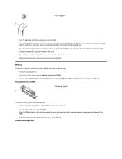
...). 2. Press the RIMM straight into its connector.
See the documentation for the card for information about the card's cable connections. 6.
Installing a RIMM 1 Filler bracket
3. Insert the expansion card into the expansion-card slot.
4. Connect any cables that should be attached to access the RIMMs. 3. Insert the card's edge connector firmly into the...
Service Manual - Page 17
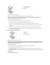
... assembly. Set the microprocessor package lightly in the ZIF socket. Because the system uses a ZIF socket, there is no need to that the system data area correctly identifies the type of the pins on the system.
7. d. When the microprocessor package is not all the pins are headed into place, securing the...
Service Manual - Page 19

... the chassis intrusion detector. Push evenly on both sides of
microprocessor installed. Replace the computer cover. 9. While in System Setup, confirm that the system data area correctly identifies the type of the system board as you slide and lock it into position (do not twist the system board). 5. Back to the...
Service Manual - Page 20
...internal components. If a wrist grounding strap is not on the computer chassis, such as explained in "Precautionary Measures."
Removing and Replacing Parts: Dell™ OptiPlex™ GX200 System Service Manual
Overview
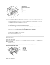
System Power Supply
Recommended Tools
System Board Components
Precautionary Measures
Expansion Cards
Computer Cover
Riser Boards
Internal View
Memory
Front...
Service Manual - Page 21
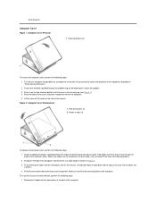
... chassis. Computer Cover Replacement 1 Release buttons (2) 2 Hooks in on the computer cover. To reset the chassis intrusion detector, perform the following steps: 1. Reconnect all cable connections, especially those that they will prevent the cover from closing properly. 2.
Service Manual - Page 26
... 1 on the IDE1 connector to avoid possible damage to the 40-pin interface connector on the back of the hard-disk drive (see Figure 11). Connect one of the device connectors on the EIDE cable to your upgrade kit (see Figure 11).
Figure 12. Align the four screw holes of the...
Service Manual - Page 27
Pin 1 is not already connected, connect the other end of the way. While in its extended position.
Refer to... 0 option under Primary Drive n. 8. Partition and logically format your operating system for your drive before proceeding to your system. Connect a DC power cable into drive A, and turn on the peripherals. 6. Insert a bootable diskette into the power input connector on...
Service Manual - Page 32
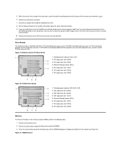
... expansion slot 1 (PCI1) 6 PCI expansion slot 2 (PCI2) 7 PCI expansion slot 3 (PCI3)
Figure 20. Connect any cables that should be attached to the
INT SPKR connector on the sound card. RIMM Removal PCI/ISA Riser Board
.... 3. Rotate the system power supply to allow you are installing the entry-level OptiPlex sound card, disconnect the internal speaker cable from the socket (see Figure 20)....
Service Manual - Page 38
... the following caution for your personal safety and to prevent damage to the system from their electrical outlets. Removing and Replacing Parts: Dell™ OptiPlex™ GX200 Systems Service Manual
Overview Recommended Tools Precautionary Measures Internal Views Computer Cover Front Bezel Eject, Power, and Reset Buttons Front-Panel Inserts Control Panel Chassis...
Service Manual - Page 54
... the following steps:
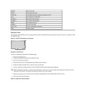
1. Remove the computer cover. 2. If necessary, disconnect any cables connected to maintain Federal Communications Commission (FCC) certification of the system and keep dust and dirt... Riser board connector Serial port connector Primary microprocessor connector USB connectors
Expansion Cards
Each GX200 chassis can accommodate 32-bit PCI expansion cards and 16-bit and 8-bit ISA...
Service Manual - Page 61
Removing and Replacing Parts: Dell™ OptiPlex™ GX200 Systems Service Manual
Overview Recommended Tools Precautionary Measures ...removal procedure in this manual require the use a wrist grounding strap as explained in the Dell OptiPlex small formfactor chassis GX200 system. If you perform any telephone or telecommunication lines from their electrical outlets. Back to 20...
Service Manual - Page 74
... remove an expansion card, perform the following steps:
1. If necessary, disconnect any cables connected to two half-length 32-bit PCI expansion cards. The brackets also keep dust and... board connector Serial port connector Primary microprocessor connector USB connectors
Expansion Cards
The small form-factor GX200 chassis can accommodate up to the card. 3. Figure 23. Remove the screw on . ...
Similar Questions

What Motherboard And Cpu Will Be The Best Fit For The Dell Desktop Optiplex 740
(Posted by rmalone3108 2 years ago)

Dell Desktop Optiplex 360 How To Connect Two Monitors
(Posted by mekesdaka 10 years ago)

Dell Desktop Optiplex 330 Does Not Startup Internal P2 Connection Has Defect
(Posted by xydgari 10 years ago)

How To Set Up Tv Tuner Using Local Cable Connection On Dell Inspiron 2320
(Posted by nadeb 10 years ago)

How To Connect Dell Optiplex 390 Desktop To A Wireless Network?
(Posted by blobydan 10 years ago)