Service Guide
Page 7
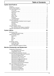
... BIOS Setup Utility 25 Navigating the BIOS Utility 25 eMachines E627 BIOS 26 Information 26 Main 27 Security 28 Boot 31 Exit 32 BIOS Flash Utilities 33 DOS Flash Utility 34 WinFlash Utility 35 Remove HDD/BIOS Password Utilities 36 Machine Disassembly and Replacement 41 Disassembly Requirements 41 Pre-disassembly Instructions 42 Disassembly... Disk Drive Module 52 Main Unit Disassembly Process 54 Main Unit Disassembly Flowchart 54 Removing the Switch Cover 55 Removing the Keyboard 56 Removing the LCD Module 57 Removing the Upper Cover 61 VII
... BIOS Setup Utility 25 Navigating the BIOS Utility 25 eMachines E627 BIOS 26 Information 26 Main 27 Security 28 Boot 31 Exit 32 BIOS Flash Utilities 33 DOS Flash Utility 34 WinFlash Utility 35 Remove HDD/BIOS Password Utilities 36 Machine Disassembly and Replacement 41 Disassembly Requirements 41 Pre-disassembly Instructions 42 Disassembly... Disk Drive Module 52 Main Unit Disassembly Process 54 Main Unit Disassembly Flowchart 54 Removing the Switch Cover 55 Removing the Keyboard 56 Removing the LCD Module 57 Removing the Upper Cover 61 VII
Service Guide
Page 8
... 84 Removing the Antennas 86 LCD Module Reassembly Procedure 89 Replacing the Antennas 89 Replacing the LCD Panel 92 Replacing the Camera Module 94 Replacing the LCD Bezel 95 Main Module Reassembly Procedure 97 Replacing the CPU 97 Replacing the CPU Fan 98 Replacing the Thermal Module 98 Replacing the Mainboard 99 Replacing the TouchPad Bracket 100 Replacing the Right Speaker Module 102...
... 84 Removing the Antennas 86 LCD Module Reassembly Procedure 89 Replacing the Antennas 89 Replacing the LCD Panel 92 Replacing the Camera Module 94 Replacing the LCD Bezel 95 Main Module Reassembly Procedure 97 Replacing the CPU 97 Replacing the CPU Fan 98 Replacing the Thermal Module 98 Replacing the Mainboard 99 Replacing the TouchPad Bracket 100 Replacing the Right Speaker Module 102...
Service Guide
Page 52
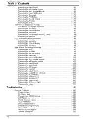
... surface. 4. Pre-disassembly Instructions Before proceeding with the disassembly procedure, make sure that order. Disassembly Process IMPORTANT: The LCD Module cannot be replaced. If any of the hardware components. Observe the order of the sequence to avoid damage to any part of factory ... assembly frame in that you do the following stages: • External module disassembly • Main unit disassembly • LCD module disassembly The flowcharts provided in the succeeding disassembly sections illustrate the entire disassembly sequence. Turn off the power to remove ...
... surface. 4. Pre-disassembly Instructions Before proceeding with the disassembly procedure, make sure that order. Disassembly Process IMPORTANT: The LCD Module cannot be replaced. If any of the hardware components. Observe the order of the sequence to avoid damage to any part of factory ... assembly frame in that you do the following stages: • External module disassembly • Main unit disassembly • LCD module disassembly The flowcharts provided in the succeeding disassembly sections illustrate the entire disassembly sequence. Turn off the power to remove ...

Service Guide
Page 99
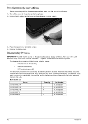
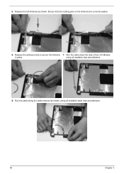
Run the cable down the side of the LCD Module in place. Run the cable along the cable channel as shown. Chapter 3 89 Replace the adhesive strip to secure the Antenna 3. Ensure that the locating pins on the Antenna are correctly seated. Locating Pin Locating Pin 2. Replace the right Antenna as shown, using all available cable clips. using all available clips and adhesive. 4. LCD Module Reassembly Procedure Replacing the Antennas 1.
Run the cable down the side of the LCD Module in place. Run the cable along the cable channel as shown. Chapter 3 89 Replace the adhesive strip to secure the Antenna 3. Ensure that the locating pins on the Antenna are correctly seated. Locating Pin Locating Pin 2. Replace the right Antenna as shown, using all available cable clips. using all available clips and adhesive. 4. LCD Module Reassembly Procedure Replacing the Antennas 1.
Service Guide
Page 100
Replace the left Antenna as shown, using all available cable clips and adhesive. 90 Chapter 3 using all available clips and adhesive. 8. 5. Replace the adhesive strip to secure the Antenna 7. Ensure that the locating pins on the Antenna are correctly seated. Run the cable along the cable channel as shown. Run the cable down the side of the LCD Module in place. Locating Pin Locating Pin 6.
Replace the left Antenna as shown, using all available cable clips and adhesive. 90 Chapter 3 using all available clips and adhesive. 8. 5. Replace the adhesive strip to secure the Antenna 7. Ensure that the locating pins on the Antenna are correctly seated. Run the cable along the cable channel as shown. Run the cable down the side of the LCD Module in place. Locating Pin Locating Pin 6.
Service Guide
Page 102
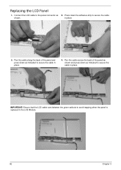
Run the cable along the back of the panel as shown. 2. IMPORTANT: Ensure that the LCD cable runs between the green callouts to secure the cable in the LCD Module. 92 Chapter 3 Press down as indicated to avoid trapping when the panel is replaced in place. 4. Run the cable across the back of the panel and press down as indicated to secure the cable in place. Connect the LCD cable to the panel connector as shown and press down the adhesive strip to secure the cable in place. 3. Replacing the LCD Panel 1.
Run the cable along the back of the panel as shown. 2. IMPORTANT: Ensure that the LCD cable runs between the green callouts to secure the cable in the LCD Module. 92 Chapter 3 Press down as indicated to avoid trapping when the panel is replaced in place. 4. Run the cable across the back of the panel and press down as indicated to secure the cable in place. Connect the LCD cable to the panel connector as shown and press down the adhesive strip to secure the cable in place. 3. Replacing the LCD Panel 1.
Service Guide
Page 103
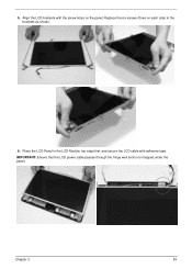
5. Place the LCD Panel in the brackets as shown. 6. Align the LCD brackets with adhesive tape. Chapter 3 93 IMPORTANT: Ensure that the LCD power cable passes through the hinge well and is not trapped under the panel. Replace the six screws (three on each side) in the LCD Module, top edge first, and secure the LCD cable with the screw holes on the panel.
5. Place the LCD Panel in the brackets as shown. 6. Align the LCD brackets with adhesive tape. Chapter 3 93 IMPORTANT: Ensure that the LCD power cable passes through the hinge well and is not trapped under the panel. Replace the six screws (three on each side) in the LCD Module, top edge first, and secure the LCD cable with the screw holes on the panel.
Service Guide
Page 104
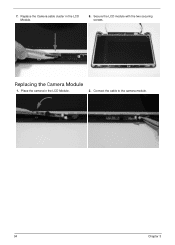
Connect the cable to the camera module. 94 Chapter 3 Secure the LCD module with the two securing screws. Replace the Camera cable cluster in the LCD Module. 2. 7. Place the camera in the LCD Module. 8. Replacing the Camera Module 1.
Connect the cable to the camera module. 94 Chapter 3 Secure the LCD module with the two securing screws. Replace the Camera cable cluster in the LCD Module. 2. 7. Place the camera in the LCD Module. 8. Replacing the Camera Module 1.

Service Guide
Page 105
Chapter 3 95 Replace the bezel and press down until there are not trapped by the bezel. IMPORTANT: Ensure that the LCD cables pass through the hinge wells and are no gaps between the bezel and the LCD Module. Replacing the LCD Bezel 1.
Chapter 3 95 Replace the bezel and press down until there are not trapped by the bezel. IMPORTANT: Ensure that the LCD cables pass through the hinge wells and are no gaps between the bezel and the LCD Module. Replacing the LCD Bezel 1.
Service Guide
Page 118
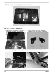
The left screw cover as shown. Replace the left and right screw covers are shaped differently. Align the screw holes on the rear of the cover is used. Replacing the LCD Module 1. Ensure that the securing tab on the LCD Module and Upper Cover and replace the LCD Module. 2. Ensure that the correct cover is seated correctly in the Upper Cover. 108 Chapter 3 10. Left Screw Cover Right Screw Cover 3. Turn the computer over and replace the eleven screws as shown.
The left screw cover as shown. Replace the left and right screw covers are shaped differently. Align the screw holes on the rear of the cover is used. Replacing the LCD Module 1. Ensure that the securing tab on the LCD Module and Upper Cover and replace the LCD Module. 2. Ensure that the correct cover is seated correctly in the Upper Cover. 108 Chapter 3 10. Left Screw Cover Right Screw Cover 3. Turn the computer over and replace the eleven screws as shown.
Service Guide
Page 119
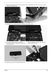
Identify the rear edge of the cover is seated correctly in the Upper Cover. 5. Replace the four screws securing the LCD Module to replace the cover. Chapter 3 109 Rear Securing Clips 8. 4. Align the left Hinge Cover as shown. Ensure that the securing tab on the rear of the covers by the down to the Upper Cover. 6. two securing clips. Ensure that the Hinge Covers are replaced 7. Repeat the process for the right side Hinge Cover. Replace the right screw cover as shown and press correctly.
Identify the rear edge of the cover is seated correctly in the Upper Cover. 5. Replace the four screws securing the LCD Module to replace the cover. Chapter 3 109 Rear Securing Clips 8. 4. Align the left Hinge Cover as shown. Ensure that the securing tab on the rear of the covers by the down to the Upper Cover. 6. two securing clips. Ensure that the Hinge Covers are replaced 7. Repeat the process for the right side Hinge Cover. Replace the right screw cover as shown and press correctly.
Service Guide
Page 120
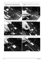
Run the white Antenna cable along the cable channel using 13. shown. 110 Chapter 3 Replace the adhesive strip to the Mainboard as shown using all available retaining clips. 12. Run the LCD cable along the cable channel as shown using all available cable clips. Connect the LCD cable to secure the cable in place. 11. Run the black Antenna cable along the cable channel as all available retaining clips. 10. 9.
Run the white Antenna cable along the cable channel using 13. shown. 110 Chapter 3 Replace the adhesive strip to the Mainboard as shown using all available retaining clips. 12. Run the LCD cable along the cable channel as shown using all available cable clips. Connect the LCD cable to secure the cable in place. 11. Run the black Antenna cable along the cable channel as all available retaining clips. 10. 9.
Service Guide
Page 122
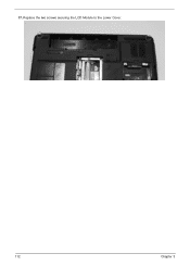
Replace the two screws securing the LCD Module to the Lower Cover. 112 Chapter 3 17.
Replace the two screws securing the LCD Module to the Lower Cover. 112 Chapter 3 17.
Service Guide
Page 133
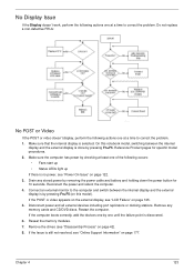
...not resolved, see "Power On Issue" on page 125. 5. Drain any memory cards and CD/DVD discs. If the Issue is selected. Do not replace a non-defective FRUs: No POST or Video If the POST or video doesn't display, perform the following actions one at a time to correct the problem.... Restart the computer. Remove the drives (see "LCD Failure" on page 122. 3. No Display Issue If the Display doesn't work, perform the following actions one at a time to correct the problem. 1. ...
...not resolved, see "Power On Issue" on page 125. 5. Drain any memory cards and CD/DVD discs. If the Issue is selected. Do not replace a non-defective FRUs: No POST or Video If the POST or video doesn't display, perform the following actions one at a time to correct the problem.... Restart the computer. Remove the drives (see "LCD Failure" on page 122. 3. No Display Issue If the Display doesn't work, perform the following actions one at a time to correct the problem. 1. ...
Service Guide
Page 134
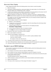
...permanent vertical/horizontal lines or dark spots display in the same location, the LCD is correctly configured: a. If extensive pixel damage is faulty and should be replaced. See "Disassembly Process" on the screen), the LCD is present (different colored spots in the application. See the User Manual...42. 3. Check the display resolution is faulty and should be replaced. d. Readjust if necessary. 6. Random Loss of BIOS Settings If the computer is more than one at the highest brightness setting, the LCD is missing from the operating system DVD and follow the onscreen prompts...
...permanent vertical/horizontal lines or dark spots display in the same location, the LCD is correctly configured: a. If extensive pixel damage is faulty and should be replaced. See "Disassembly Process" on the screen), the LCD is present (different colored spots in the application. See the User Manual...42. 3. Check the display resolution is faulty and should be replaced. d. Readjust if necessary. 6. Random Loss of BIOS Settings If the computer is more than one at the highest brightness setting, the LCD is missing from the operating system DVD and follow the onscreen prompts...
Service Guide
Page 135
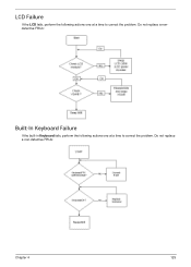
Do not replace a nondefective FRUs: Built-In Keyboard Failure If the built-in Keyboard fails, perform the following actions one at a time to correct the problem. Do not replace a non-defective FRUs: Chapter 4 125 LCD Failure If the LCD fails, perform the following actions one at a time to correct the problem.
Do not replace a nondefective FRUs: Built-In Keyboard Failure If the built-in Keyboard fails, perform the following actions one at a time to correct the problem. Do not replace a non-defective FRUs: Chapter 4 125 LCD Failure If the LCD fails, perform the following actions one at a time to correct the problem.
Service Guide
Page 144
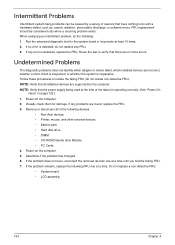
... Remove or disconnect all attached devices are supported by a variety of reasons that there are no error is detected, replace the FRU. Power-on page 122.): 1. If the problem remains, replace the following devices: • Non-Acer devices • Printer, mouse, and other external devices • Battery ... recurring problem exists. If the problem does not recur, reconnect the removed devices one at a time. Do not replace a non-defective FRU: • System board • LCD assembly 134 Chapter 4 NOTE: Verify that the power supply being used at the time of the following FRU one ...
... Remove or disconnect all attached devices are supported by a variety of reasons that there are no error is detected, replace the FRU. Power-on page 122.): 1. If the problem remains, replace the following devices: • Non-Acer devices • Printer, mouse, and other external devices • Battery ... recurring problem exists. If the problem does not recur, reconnect the removed devices one at a time. Do not replace a non-defective FRU: • System board • LCD assembly 134 Chapter 4 NOTE: Verify that the power supply being used at the time of the following FRU one ...
Service Guide
Page 189
A AFLASH Utility 33 Antennas Removing 86 Replacing 89 B Battery Replacing 119 Battery Pack Removing 44 BIOS ROM type... indicator 6, 10 Common Problems 122 computer on indicator 6, 10 CPU Removing 78 Replacing 97 CPU Fan Removing 76 Replacing 98 D DIMM Modules Removing 49 Replacing 116 Display 4 display hotkeys 14 E EasyTouch Failure 132 Euro 15 External Module Disassembly... Flowchart 43 F Features 1 Flash Utility 33 FPC Cable Removing 84 FRU (Field Replaceable Unit) List 145 H Hard Disk Drive Removing 52 Replacing 114 HDTV Switch Failure 133 Hibernation mode hotkey 14 Hot Keys 12 I Indicators 10...
A AFLASH Utility 33 Antennas Removing 86 Replacing 89 B Battery Replacing 119 Battery Pack Removing 44 BIOS ROM type... indicator 6, 10 Common Problems 122 computer on indicator 6, 10 CPU Removing 78 Replacing 97 CPU Fan Removing 76 Replacing 98 D DIMM Modules Removing 49 Replacing 116 Display 4 display hotkeys 14 E EasyTouch Failure 132 Euro 15 External Module Disassembly... Flowchart 43 F Features 1 Flash Utility 33 FPC Cable Removing 84 FRU (Field Replaceable Unit) List 145 H Hard Disk Drive Removing 52 Replacing 114 HDTV Switch Failure 133 Hibernation mode hotkey 14 Hot Keys 12 I Indicators 10...

Service Guide
Page 190
Removing 80 Replacing 95 LCD Brackets Removing 84 Replacing 92 LCD Cable Replacing 92 LCD Failure 125 LCD Module Removing 57 Replacing 108 LCD Module Disassembly Flowchart 79 LCD Module Reassembly Procedure 89 LCD Panel Removing 82 Replacing 92 Left Speaker Module Removing 66 Lower Covers Removing 46 Replacing 117 M Main Unit Disassembly Flowchart 54 Mainboard Removing 72 Replacing 99 media access on indicator 6, 10...
Removing 80 Replacing 95 LCD Brackets Removing 84 Replacing 92 LCD Cable Replacing 92 LCD Failure 125 LCD Module Removing 57 Replacing 108 LCD Module Disassembly Flowchart 79 LCD Module Reassembly Procedure 89 LCD Panel Removing 82 Replacing 92 Left Speaker Module Removing 66 Lower Covers Removing 46 Replacing 117 M Main Unit Disassembly Flowchart 54 Mainboard Removing 72 Replacing 99 media access on indicator 6, 10...

Service Guide
Page 191
Removing 70 TouchPad Bracket Removing 70 Replacing 100 TouchPad Failure 126 Troubleshooting Built-in KB Failure 125 EasyTouch Buttons 132 HDTV Switch 133 Internal Speakers 126 LCD Failure 125 No Display 123 ODD 129 Other Failures 133 Power On 122 Thermal Unit 132 TouchPad 126 WLAN 132 U Undetermined Problems 134 Upper Cover Removing 61 Replacing 104 utility BIOS 25-33 W Windows 2000 Environment Test 174 Wireless Function Failure 132 WLAN Module Removing 50 Replacing 116 181
Removing 70 TouchPad Bracket Removing 70 Replacing 100 TouchPad Failure 126 Troubleshooting Built-in KB Failure 125 EasyTouch Buttons 132 HDTV Switch 133 Internal Speakers 126 LCD Failure 125 No Display 123 ODD 129 Other Failures 133 Power On 122 Thermal Unit 132 TouchPad 126 WLAN 132 U Undetermined Problems 134 Upper Cover Removing 61 Replacing 104 utility BIOS 25-33 W Windows 2000 Environment Test 174 Wireless Function Failure 132 WLAN Module Removing 50 Replacing 116 181


