Service Guide
Page 7
... the BIOS Utility 25 eMachines E627 BIOS 26 Information 26 Main 27 Security 28 Boot 31 Exit 32 BIOS Flash Utilities 33 DOS Flash Utility 34 WinFlash Utility 35 Remove HDD/BIOS Password Utilities 36 Machine Disassembly and Replacement 41 Disassembly Requirements 41 ...Pre-disassembly Instructions 42 Disassembly Process 42 External Module Disassembly Process 43 External Modules Disassembly Flowchart 43 Removing the Battery Pack 44 Removing the SD Dummy Card 45 Removing...
... the BIOS Utility 25 eMachines E627 BIOS 26 Information 26 Main 27 Security 28 Boot 31 Exit 32 BIOS Flash Utilities 33 DOS Flash Utility 34 WinFlash Utility 35 Remove HDD/BIOS Password Utilities 36 Machine Disassembly and Replacement 41 Disassembly Requirements 41 ...Pre-disassembly Instructions 42 Disassembly Process 42 External Module Disassembly Process 43 External Modules Disassembly Flowchart 43 Removing the Battery Pack 44 Removing the SD Dummy Card 45 Removing...
Service Guide
Page 8
... Power Board 104 Replacing the Upper Cover 104 Replacing the LCD Module 108 Replacing the Keyboard 113 Replacing the Switch Cover 114 Replacing the Hard Disk Drive Module 114 Replacing the WLAN Module 116 Replacing the DIMM Modules 116 Replacing the ODD Module 117 Replacing the Lower Covers 117 Replacing the SD Dummy Card 118 Replacing the Battery 119 Troubleshooting 121 Common...
... Power Board 104 Replacing the Upper Cover 104 Replacing the LCD Module 108 Replacing the Keyboard 113 Replacing the Switch Cover 114 Replacing the Hard Disk Drive Module 114 Replacing the WLAN Module 116 Replacing the DIMM Modules 116 Replacing the ODD Module 117 Replacing the Lower Covers 117 Replacing the SD Dummy Card 118 Replacing the Battery 119 Troubleshooting 121 Common...
Service Guide
Page 52
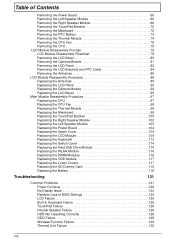
...example, if you want to the system and all power and signal cables from the system. 3. Disassembly Process IMPORTANT: The LCD Module cannot be replaced. If any of factory conditions. The disassembly process is faulty, such as the camera, antenna or LCD panel, the whole module must first ...flowcharts provided in that you must be disassembled outside of the hardware components. Place the system on a flat, stable surface. 4. Remove the battery pack. Main Screw List Screw Quantity Part Number SCREW M2.5*4 1 86.N2802.001 SCREW M2.5*6 10 86.N2802.002 SCREW M2.5*8 30 86...
...example, if you want to the system and all power and signal cables from the system. 3. Disassembly Process IMPORTANT: The LCD Module cannot be replaced. If any of factory conditions. The disassembly process is faulty, such as the camera, antenna or LCD panel, the whole module must first ...flowcharts provided in that you must be disassembled outside of the hardware components. Place the system on a flat, stable surface. 4. Remove the battery pack. Main Screw List Screw Quantity Part Number SCREW M2.5*4 1 86.N2802.001 SCREW M2.5*6 10 86.N2802.002 SCREW M2.5*8 30 86...
Service Guide
Page 83
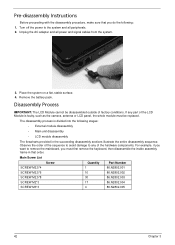
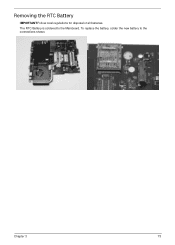
Chapter 3 73 The RTC Battery is soldered to the connections shown. Removing the RTC Battery IMPORTANT:Follow local regulations for disposal of all batteries. To replace the battery, solder the new battery to the Mainboard.
Chapter 3 73 The RTC Battery is soldered to the connections shown. Removing the RTC Battery IMPORTANT:Follow local regulations for disposal of all batteries. To replace the battery, solder the new battery to the Mainboard.
Service Guide
Page 129
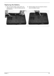
Slide and hold the battery release latch to secure the battery in the direction shown to the release position (1), insert the battery pack and press down (2). 2. Replacing the Battery 1. Slide the battery lock in place. 2 1 Chapter 3 119
Slide and hold the battery release latch to secure the battery in the direction shown to the release position (1), insert the battery pack and press down (2). 2. Replacing the Battery 1. Slide the battery lock in place. 2 1 Chapter 3 119
Service Guide
Page 133
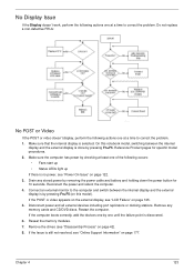
...that the internal display is discovered. 6. Reconnect the power and reboot the computer. 4. Restart the computer. Reseat the memory modules. 7. Do not replace a non-defective FRUs: No POST or Video If the POST or video doesn't display, perform the following actions one at a time to correct... Connect an external monitor to the computer and switch between the internal display and the external display is by removing the power cable and battery and holding down the power button for specific model procedures. 2. Drain any memory cards and CD/DVD discs. If the computer boots ...
...that the internal display is discovered. 6. Reconnect the power and reboot the computer. 4. Restart the computer. Reseat the memory modules. 7. Do not replace a non-defective FRUs: No POST or Video If the POST or video doesn't display, perform the following actions one at a time to correct... Connect an external monitor to the computer and switch between the internal display and the external display is by removing the power cable and battery and holding down the power button for specific model procedures. 2. Drain any memory cards and CD/DVD discs. If the computer boots ...
Service Guide
Page 134
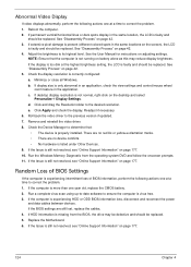
... Manager to determine that the computer is still not resolved, see "Online Support Information" on battery alone as this may be defective and should be replaced. 5. If the Issue is not running on page 177. 124 Chapter 4 Run a complete... than one at a time to correct the problem. 1. If extensive pixel damage is faulty and should be replaced. See the User Manual for instructions on the screen), the LCD is present (different colored spots in the application... video displays abnormally, perform the following actions one year old, replace the CMOS battery. 2.
... Manager to determine that the computer is still not resolved, see "Online Support Information" on battery alone as this may be defective and should be replaced. 5. If the Issue is not running on page 177. 124 Chapter 4 Run a complete... than one at a time to correct the problem. 1. If extensive pixel damage is faulty and should be replaced. See the User Manual for instructions on the screen), the LCD is present (different colored spots in the application... video displays abnormally, perform the following actions one year old, replace the CMOS battery. 2.
Service Guide
Page 143
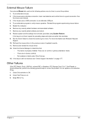
... from a known good date using System Restore. If the Issue is a good connection. If the mouse uses a wireless connection, insert new batteries and confirm there is still not resolved, see Windows Help and Support. 10. Reinstall the program experiencing mouse failure. 5. Restart the computer. 6. ..., PCI Express Card, 5-in-1 Card Reader or Volume Wheel fail, perform the following actions one at a time to correct the problem. 1. Do not replace a non-defective FRUs: 1. If the mouse uses a USB connection, try an alternate USB port. 4. Remove and reinstall the mouse driver. 12. Swap...
... from a known good date using System Restore. If the Issue is a good connection. If the mouse uses a wireless connection, insert new batteries and confirm there is still not resolved, see Windows Help and Support. 10. Reinstall the program experiencing mouse failure. 5. Restart the computer. 6. ..., PCI Express Card, 5-in-1 Card Reader or Volume Wheel fail, perform the following actions one at a time to correct the problem. 1. Do not replace a non-defective FRUs: 1. If the mouse uses a USB connection, try an alternate USB port. 4. Remove and reinstall the mouse driver. 12. Swap...
Service Guide
Page 144
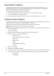
...If no more errors. NOTE: Verify that all of the failure is detected, replace the FRU. If the problem remains, replace the following devices: • Non-Acer devices • Printer, mouse, and other external devices • Battery pack • Hard disk drive • DIMM • CD-ROM/Diskette ...drive Module • PC Cards 4. If any error is operating correctly. (See "Power On Issue" on the computer. 5. FRU replacement should be caused by the computer. Rerun ...
...If no more errors. NOTE: Verify that all of the failure is detected, replace the FRU. If the problem remains, replace the following devices: • Non-Acer devices • Printer, mouse, and other external devices • Battery pack • Hard disk drive • DIMM • CD-ROM/Diskette ...drive Module • PC Cards 4. If any error is operating correctly. (See "Power On Issue" on the computer. 5. FRU replacement should be caused by the computer. Rerun ...
Service Guide
Page 189
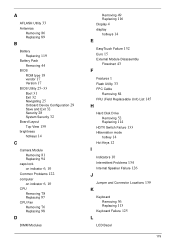
A AFLASH Utility 33 Antennas Removing 86 Replacing 89 B Battery Replacing 119 Battery Pack Removing 44 BIOS ROM type 18 vendor 17 Version 17 BIOS Utility 25-33 Boot 31 Exit 32 Navigating 25 Onboard Device Configuration 29 ...Save and Exit 32 Security 28 System Security 32 Board Layout Top View 139 brightness hotkeys 14 C Camera Module Removing 81 Replacing 94 caps lock...
A AFLASH Utility 33 Antennas Removing 86 Replacing 89 B Battery Replacing 119 Battery Pack Removing 44 BIOS ROM type 18 vendor 17 Version 17 BIOS Utility 25-33 Boot 31 Exit 32 Navigating 25 Onboard Device Configuration 29 ...Save and Exit 32 Security 28 System Security 32 Board Layout Top View 139 brightness hotkeys 14 C Camera Module Removing 81 Replacing 94 caps lock...

Service Guide
Page 190
... P Panel 5 Bottom 8 PC Card 10 Power Board Removing 65 Replacing 104 Power On Failure 122 R Right Speaker Module Removing 68 Replacing 102 RTC Battery Removing 73 S SD Dummy Card Removing 45 Replacing 118 Speakers Removing 66, 68 speakers hotkey 14 Switch Cover Removing 55 Replacing 114 System Block Diagram 4 T Test Compatible Components 173 Thermal Module...
... P Panel 5 Bottom 8 PC Card 10 Power Board Removing 65 Replacing 104 Power On Failure 122 R Right Speaker Module Removing 68 Replacing 102 RTC Battery Removing 73 S SD Dummy Card Removing 45 Replacing 118 Speakers Removing 66, 68 speakers hotkey 14 Switch Cover Removing 55 Replacing 114 System Block Diagram 4 T Test Compatible Components 173 Thermal Module...


