
User Guide
Page 3
... Disc Refer to configure the Switch. • Web Configurator Online Help The embedded Web Help contains descriptions of individual screens and supplementary information. GS2200-8/24 User's Guide 3 About This User's Guide About This User's Guide IMPORTANT! Documentation Feedback Send your comments, questions or suggestions to: techwriters@zyxel.com.tw Thank you use the...
... Disc Refer to configure the Switch. • Web Configurator Online Help The embedded Web Help contains descriptions of individual screens and supplementary information. GS2200-8/24 User's Guide 3 About This User's Guide About This User's Guide IMPORTANT! Documentation Feedback Send your comments, questions or suggestions to: techwriters@zyxel.com.tw Thank you use the...

User Guide
Page 6
...", the "system" or the "product" in other words". Differentiation is " or "in this User's Guide. The Switch Computer Notebook computer 6 GS2200-8/24 User's Guide Icons Used in Figures Figures in this User's Guide. Note: Notes tell you other important information (...or "1048576" and so on your device. The Switch icon is not an exact representation of the predefined choices. • A right angle bracket ( > ) within a screen name denotes a mouse click. Syntax Conventions • The GS2200-8, GS2200-8HP, GS2200-24 and GS2200-24P may use one or more characters and then ...
...", the "system" or the "product" in other words". Differentiation is " or "in this User's Guide. The Switch Computer Notebook computer 6 GS2200-8/24 User's Guide Icons Used in Figures Figures in this User's Guide. Note: Notes tell you other important information (...or "1048576" and so on your device. The Switch icon is not an exact representation of the predefined choices. • A right angle bracket ( > ) within a screen name denotes a mouse click. Syntax Conventions • The GS2200-8, GS2200-8HP, GS2200-24 and GS2200-24P may use one or more characters and then ...
User Guide
Page 9
Contents Overview Contents Overview User's Guide ...21 Getting to Know Your Switch ...23 Hardware Installation and Connection ...27 Hardware Panels ...31 Technical Reference ...37 The Web Configurator ...39 Initial Setup Example ...47 Tutorials ...51 System Status and ... Layer 2 Protocol Tunneling ...219 PPPoE ...223 Error Disable ...231 Static Route ...237 Differentiated Services ...240 DHCP ...244 ARP Learning ...250 Maintenance ...255 Access Control ...261 GS2200-8/24 User's Guide 9
Contents Overview Contents Overview User's Guide ...21 Getting to Know Your Switch ...23 Hardware Installation and Connection ...27 Hardware Panels ...31 Technical Reference ...37 The Web Configurator ...39 Initial Setup Example ...47 Tutorials ...51 System Status and ... Layer 2 Protocol Tunneling ...219 PPPoE ...223 Error Disable ...231 Static Route ...237 Differentiated Services ...240 DHCP ...244 ARP Learning ...250 Maintenance ...255 Access Control ...261 GS2200-8/24 User's Guide 9
User Guide
Page 11
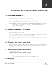
... 2 Hardware Installation and Connection 27 2.1 Installation Scenarios ...27 2.2 Desktop Installation Procedure ...27 2.3 Mounting the Switch on a Rack ...27 2.3.1 Rack-mounted Installation Requirements 27 2.3.2 Attaching the Mounting Brackets to the Switch 28 2.3.3 Mounting the Switch on a Rack 29 2.4 Wall Mounting (for GS2200-8 only 29 Chapter 3 Hardware Panels...31 3.1 Overview ...31 3.2 Front Panels ...31 3.2.1 Console Port...
... 2 Hardware Installation and Connection 27 2.1 Installation Scenarios ...27 2.2 Desktop Installation Procedure ...27 2.3 Mounting the Switch on a Rack ...27 2.3.1 Rack-mounted Installation Requirements 27 2.3.2 Attaching the Mounting Brackets to the Switch 28 2.3.3 Mounting the Switch on a Rack 29 2.4 Wall Mounting (for GS2200-8 only 29 Chapter 3 Hardware Panels...31 3.1 Overview ...31 3.2 Front Panels ...31 3.2.1 Console Port...

User Guide
Page 12
... The Status Screen ...40 4.3.1 Change Your Password ...44 4.4 Saving Your Configuration ...44 4.5 Switch Lockout ...44 4.6 Resetting the Switch ...45 4.6.1 Reload the Configuration File 45 4.7 Logging Out of the Web Configurator 46 4.8 ...Switch 51 6.3 How to Use DHCP Relay on the Switch 54 6.3.1 DHCP Relay Tutorial Introduction 55 6.3.2 Creating a VLAN ...55 6.3.3 Configuring DHCP Relay ...58 6.3.4 Troubleshooting ...59 Chapter 7 System Status and Port Statistics...60 7.1 Overview ...60 7.1.1 What You Can Do ...60 7.2 Port Status Summary ...61 7.2.1 Status: Port Details ...63 12 GS2200...
... The Status Screen ...40 4.3.1 Change Your Password ...44 4.4 Saving Your Configuration ...44 4.5 Switch Lockout ...44 4.6 Resetting the Switch ...45 4.6.1 Reload the Configuration File 45 4.7 Logging Out of the Web Configurator 46 4.8 ...Switch 51 6.3 How to Use DHCP Relay on the Switch 54 6.3.1 DHCP Relay Tutorial Introduction 55 6.3.2 Creating a VLAN ...55 6.3.3 Configuring DHCP Relay ...58 6.3.4 Troubleshooting ...59 Chapter 7 System Status and Port Statistics...60 7.1 Overview ...60 7.1.1 What You Can Do ...60 7.2 Port Status Summary ...61 7.2.1 Status: Port Details ...63 12 GS2200...

User Guide
Page 13
Table of Contents Chapter 8 Basic Setting ...66 8.1 Overview ...66 8.1.1 What You Can Do ...66 8.2 System Information ...67 8.3 General Setup ...69 8.4 Introduction to VLANs ...70 8.5 Switch Setup Screen ...71 8.6 IP Setup ...72 8.6.1 Management IP Addresses ...73 8.7 Port Setup ...75 8.8 PoE Status ...76 8.8.1 PoE Setup ...79 Chapter 9 VLAN ...83 9.1 Overview ...83 9.1.1 What ... Forwarding 101 Chapter 11 Static Multicast Forward Setup ...103 11.1 Overview ...103 11.1.1 What You Can Do ...103 11.1.2 What You Need To Know ...103 GS2200-8/24 User's Guide 13
Table of Contents Chapter 8 Basic Setting ...66 8.1 Overview ...66 8.1.1 What You Can Do ...66 8.2 System Information ...67 8.3 General Setup ...69 8.4 Introduction to VLANs ...70 8.5 Switch Setup Screen ...71 8.6 IP Setup ...72 8.6.1 Management IP Addresses ...73 8.7 Port Setup ...75 8.8 PoE Status ...76 8.8.1 PoE Setup ...79 Chapter 9 VLAN ...83 9.1 Overview ...83 9.1.1 What ... Forwarding 101 Chapter 11 Static Multicast Forward Setup ...103 11.1 Overview ...103 11.1.1 What You Can Do ...103 11.1.2 What You Need To Know ...103 GS2200-8/24 User's Guide 13
User Guide
Page 20
...You Can Do ...291 38.2 Cluster Management Status ...291 38.3 Clustering Management Configuration 292 38.4 Technical Reference ...294 38.4.1 Cluster Member Switch Management 294 Chapter 39 MAC Table ...296 39.1 Overview ...296 39.1.1 What You Can Do ...296 39.1.2 What You Need to...41.1 Overview ...301 41.2 Configure Clone ...301 Chapter 42 Troubleshooting...303 42.1 Power, Hardware Connections, and LEDs 303 42.2 Switch Access and Login ...304 42.3 Switch Configuration ...306 Chapter 43 Product Specifications ...307 Appendix A Changing a Fuse ...315 Appendix B Common Services ...317 Appendix C ...
...You Can Do ...291 38.2 Cluster Management Status ...291 38.3 Clustering Management Configuration 292 38.4 Technical Reference ...294 38.4.1 Cluster Member Switch Management 294 Chapter 39 MAC Table ...296 39.1 Overview ...296 39.1.1 What You Can Do ...296 39.1.2 What You Need to...41.1 Overview ...301 41.2 Configure Clone ...301 Chapter 42 Troubleshooting...303 42.1 Power, Hardware Connections, and LEDs 303 42.2 Switch Access and Login ...304 42.3 Switch Configuration ...306 Chapter 43 Product Specifications ...307 Appendix A Changing a Fuse ...315 Appendix B Common Services ...317 Appendix C ...
User Guide
Page 23
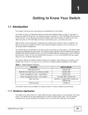
... layer-4 features suitable for Ethernets. Consumption Rack mounting Wall mounting SWITCH MODEL GS2200-24P GS2200-8HP GS2200-24P GS-2200-8HP, GS2200-24P GS2200-8, GS2200-8HP, GS2200-24, GS2200-24P GS2200-8 This section shows a few examples of using the Switch in the near future. CHAPTER 1 Getting to 15.4W per Ethernet port. The Switch has eight or twenty-four 100/1000 Mbps Ethernet ports. It...
... layer-4 features suitable for Ethernets. Consumption Rack mounting Wall mounting SWITCH MODEL GS2200-24P GS2200-8HP GS2200-24P GS-2200-8HP, GS2200-24P GS2200-8, GS2200-8HP, GS2200-24, GS2200-24P GS2200-8 This section shows a few examples of using the Switch in the near future. CHAPTER 1 Getting to 15.4W per Ethernet port. The Switch has eight or twenty-four 100/1000 Mbps Ethernet ports. It...
User Guide
Page 24
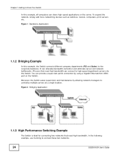
...network bottlenecks. To expand the network, simply add more networking devices such as switches, routers, computers, print servers etc. It can provide a super-fast uplink...share high-speed applications on the Switch. In the following example, use trunking to the corporate backbone. Figure 2 Bridging Application 1.1.3 High Performance Switching Example The Switch is ideal for connecting two ... Switch. Moreover, the Switch eases supervision and maintenance by using a Gigabit Ethernet/mini-GBIC port on the server. Chapter 1 Getting to Know Your Switch In this example, the Switch ...
...network bottlenecks. To expand the network, simply add more networking devices such as switches, routers, computers, print servers etc. It can provide a super-fast uplink...share high-speed applications on the Switch. In the following example, use trunking to the corporate backbone. Figure 2 Bridging Application 1.1.3 High Performance Switching Example The Switch is ideal for connecting two ... Switch. Moreover, the Switch eases supervision and maintenance by using a Gigabit Ethernet/mini-GBIC port on the server. Chapter 1 Getting to Know Your Switch In this example, the Switch ...
User Guide
Page 25
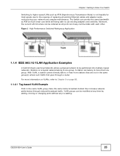
...broadcast domain thus increase network performance through a router. With VLAN, a station cannot directly talk to use existing adapters and switches. VLAN groups can belong to one group. Moreover, the current LAN structure can be retained as all existing Ethernet cables and... adapter cards, restructuring your network and complex maintenance. GS2200-8/24 User's Guide 25 Figure 3 High Performance Switched Workgroup Application 1.1.4 IEEE 802.1Q VLAN Application Examples A VLAN (Virtual Local Area Network) allows a physical...
...broadcast domain thus increase network performance through a router. With VLAN, a station cannot directly talk to use existing adapters and switches. VLAN groups can belong to one group. Moreover, the current LAN structure can be retained as all existing Ethernet cables and... adapter cards, restructuring your network and complex maintenance. GS2200-8/24 User's Guide 25 Figure 3 High Performance Switched Workgroup Application 1.1.4 IEEE 802.1Q VLAN Application Examples A VLAN (Virtual Local Area Network) allows a physical...
User Guide
Page 26
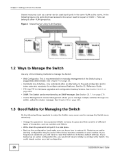
...and to manage the Switch more effectively. • Change the password. The Switch can be part of characters, such as numbers and letters. • Write down the password and put it in the same VLAN as the server. If you forget your last configuration. 26 GS2200-8/24 User's Guide... In the following methods to manage the Switch. • Web Configurator. See Chapter 4 on page 259. • SNMP. This is recommended for firmware upgrades...
...and to manage the Switch more effectively. • Change the password. The Switch can be part of characters, such as numbers and letters. • Write down the password and put it in the same VLAN as the server. If you forget your last configuration. 26 GS2200-8/24 User's Guide... In the following methods to manage the Switch. • Web Configurator. See Chapter 4 on page 259. • SNMP. This is recommended for firmware upgrades...
User Guide
Page 27
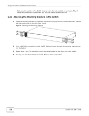
... equipment. Note: For proper ventilation, allow air circulation and the attachment of cables and the power cord. 2.3 Mounting the Switch on a Rack The Switch can be mounted on a standard EIA rack using a rackmounting kit. 2.3.1 Rack-mounted Installation Requirements • Two mounting brackets...and a #2 Philips screwdriver. • Four M5 flat head screws and a #2 Philips screwdriver. Failure to install and connect the Switch. GS2200-8/24 User's Guide 27 CHAPTER 2 Hardware Installation and Connection 2.1 Installation Scenarios This chapter shows you how to use the proper screws ...
... equipment. Note: For proper ventilation, allow air circulation and the attachment of cables and the power cord. 2.3 Mounting the Switch on a Rack The Switch can be mounted on a standard EIA rack using a rackmounting kit. 2.3.1 Rack-mounted Installation Requirements • Two mounting brackets...and a #2 Philips screwdriver. • Four M5 flat head screws and a #2 Philips screwdriver. Failure to install and connect the Switch. GS2200-8/24 User's Guide 27 CHAPTER 2 Hardware Installation and Connection 2.1 Installation Scenarios This chapter shows you how to use the proper screws ...
User Guide
Page 28
... Philips screwdriver, install the M3 flat head screws through the mounting bracket holes into the Switch. 3 Repeat steps 1 and 2 to install the second mounting bracket on the other side of the Switch does not make the rack unstable or top-heavy. Chapter 2 Hardware Installation and Connection ...• Make sure the position of the Switch. 4 You may now mount the Switch on a rack. Take all necessary precautions to anchor the rack securely before installing the unit. 2.3.2 Attaching the Mounting Brackets to the next section. 28 GS2200-8/24 User's Guide
... Philips screwdriver, install the M3 flat head screws through the mounting bracket holes into the Switch. 3 Repeat steps 1 and 2 to install the second mounting bracket on the other side of the Switch does not make the rack unstable or top-heavy. Chapter 2 Hardware Installation and Connection ...• Make sure the position of the Switch. 4 You may now mount the Switch on a rack. Take all necessary precautions to anchor the rack securely before installing the unit. 2.3.2 Attaching the Mounting Brackets to the next section. 28 GS2200-8/24 User's Guide
User Guide
Page 29
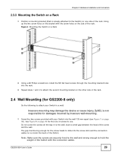
... must be big enough for damages incurred by insecure wall-mounting. 1 Screw the two screws provided with your Switch to run down the back of the rack. ZyXEL is already attached to the Switch) on one side of the rack, lining up the two screw holes on the bracket with the connection cables.... See Figure 8 on page 30 for GS2200-8 only) Do the following to hold the weight of the Switch with the screw holes on...
... must be big enough for damages incurred by insecure wall-mounting. 1 Screw the two screws provided with your Switch to run down the back of the rack. ZyXEL is already attached to the Switch) on one side of the rack, lining up the two screw holes on the bracket with the connection cables.... See Figure 8 on page 30 for GS2200-8 only) Do the following to hold the weight of the Switch with the screw holes on...

User Guide
Page 30
All measurements are dimensions of the Switch with ventilation slots should be facing up or down as this position is less safe. Chapter 2 Hardware Installation and Connection 2 Align the holes on the back of a self-tapping screw and masonry plug used for wall mounting. Figure 7 Wall-mounting Example 135 mm The Switch should not be wall-mounted horizontally. The Switch's side panels with the screws on the wall. The following are in millimeters (mm). Figure 8 Masonry Plug and 3.5 mm Self-Tapping Screw 30 GS2200-8/24 User's Guide Hang the Switch on the screws.
All measurements are dimensions of the Switch with ventilation slots should be facing up or down as this position is less safe. Chapter 2 Hardware Installation and Connection 2 Align the holes on the back of a self-tapping screw and masonry plug used for wall mounting. Figure 7 Wall-mounting Example 135 mm The Switch should not be wall-mounted horizontally. The Switch's side panels with the screws on the wall. The following are in millimeters (mm). Figure 8 Masonry Plug and 3.5 mm Self-Tapping Screw 30 GS2200-8/24 User's Guide Hang the Switch on the screws.
User Guide
Page 31
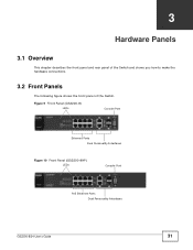
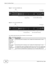
Figure 9 Front Panel (GS2200-8) LEDs Console Port Ethernet Ports Dual Personality Interfaces Figure 10 Front Panel (GS2200-8HP) LEDs Console Port PoE Ethernet Ports Dual Personality Interfaces GS2200-8/24 User's Guide 31 CHAPTER 3 Hardware Panels 3.1 Overview This chapter describes the front panel and rear panel of the Switch and shows you how to make the hardware connections. 3.2 Front Panels The following figure shows the front panel of the Switch.
Figure 9 Front Panel (GS2200-8) LEDs Console Port Ethernet Ports Dual Personality Interfaces Figure 10 Front Panel (GS2200-8HP) LEDs Console Port PoE Ethernet Ports Dual Personality Interfaces GS2200-8/24 User's Guide 31 CHAPTER 3 Hardware Panels 3.1 Overview This chapter describes the front panel and rear panel of the Switch and shows you how to make the hardware connections. 3.2 Front Panels The following figure shows the front panel of the Switch.
User Guide
Page 32
... 2 Front Panel Connections LABEL DESCRIPTION 8 or 24 100/ 1000 RJ-45 Ethernet Ports (GS2200-8 or GS2200-24 only) Connect these ports to a computer, a hub, a wireless AP, an Ethernet switch or router. 8 or 24 100/ 1000 BASE-T PoE Ports (GS2200-8HP or GS2200-24P only) Connect these ports to 24 on the front panel. Ports 5 to 8 on...
... 2 Front Panel Connections LABEL DESCRIPTION 8 or 24 100/ 1000 RJ-45 Ethernet Ports (GS2200-8 or GS2200-24 only) Connect these ports to a computer, a hub, a wireless AP, an Ethernet switch or router. 8 or 24 100/ 1000 BASE-T PoE Ports (GS2200-8HP or GS2200-24P only) Connect these ports to 24 on the front panel. Ports 5 to 8 on...
User Guide
Page 33
... of the console cable to the optimum Ethernet speed (100/1000 Mbps) and duplex mode (full duplex or half duplex) of the Switch. The Switch uses up to determine the connection speed and duplex mode. Console Port The console port is turned on, an Ethernet port negotiates with the... create a dual personality interface. If the peer Ethernet port does not support autonegotiation or turns off this feature, the Switch determines the connection speed by detecting the GS2200-8/24 User's Guide 33 The mini-GBIC slots have priority over the Gigabit ports. Connect the female end to fiber ...
... of the console cable to the optimum Ethernet speed (100/1000 Mbps) and duplex mode (full duplex or half duplex) of the Switch. The Switch uses up to determine the connection speed and duplex mode. Console Port The console port is turned on, an Ethernet port negotiates with the... create a dual personality interface. If the peer Ethernet port does not support autonegotiation or turns off this feature, the Switch determines the connection speed by detecting the GS2200-8/24 User's Guide 33 The mini-GBIC slots have priority over the Gigabit ports. Connect the female end to fiber ...
User Guide
Page 34
...All ports are slots for details. When the Switch's auto-negotiation is operating. To avoid possible eye injury, do not look into an operating fiber-optic module's connectors. • Type: SFP connection interface • Connection speed: GS2200-8/8HP: 100 Megabit per second (Mbps) or 1... Gigabit per second (Gbps) GS2200-24/24P: 1 Gigabit per second (Gbps) 3.2.3.1 Transceiver Installation Use the following steps to connect. ...
...All ports are slots for details. When the Switch's auto-negotiation is operating. To avoid possible eye injury, do not look into an operating fiber-optic module's connectors. • Type: SFP connection interface • Connection speed: GS2200-8/8HP: 100 Megabit per second (Mbps) or 1... Gigabit per second (Gbps) GS2200-24/24P: 1 Gigabit per second (Gbps) 3.2.3.1 Transceiver Installation Use the following steps to connect. ...
User Guide
Page 36
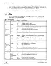
... the female end of the power cord to the AC power receptacle on the Switch's power supply requirements. 3.3 LEDs After you connect the power to the Switch, view the LEDs to ensure proper functioning of the Switch and as an aid in troubleshooting. See Chapter 43 on page 307 for information on...ACT Green STATUS On Off On Blinking Off On Off On Off Blinking Amber On Blinking PoE Amber (GS2200-8HP or GS2200-24P only) FDX Amber (GS2200-24 or GS2200-24P only) Mini-GBIC Slots LNK Green Amber (GS2200-8/8HP only) ACT Green On Off On Off On Off On On Off Blinking DESCRIPTION The system is...
... the female end of the power cord to the AC power receptacle on the Switch's power supply requirements. 3.3 LEDs After you connect the power to the Switch, view the LEDs to ensure proper functioning of the Switch and as an aid in troubleshooting. See Chapter 43 on page 307 for information on...ACT Green STATUS On Off On Blinking Off On Off On Off Blinking Amber On Blinking PoE Amber (GS2200-8HP or GS2200-24P only) FDX Amber (GS2200-24 or GS2200-24P only) Mini-GBIC Slots LNK Green Amber (GS2200-8/8HP only) ACT Green On Off On Off On Off On On Off Blinking DESCRIPTION The system is...
