
User Guide
Page 8
...device and the power source. • Do NOT attempt to repair the power adaptor or cord. ONLY qualified service personnel should be treated separately. 8 GS2200-8/24 User's Guide Connect it to a power supply of the appropriate wire gauge (see Chapter 43 on page 307 for details). • Do ...8226; Use ONLY an appropriate power adaptor or cord for your device. There is a remote risk of the same type and rating. • The POE (Power over them or stumble over Ethernet) devices that supply or receive power and their connected Ethernet cables must all cables from lightning. • ...
...device and the power source. • Do NOT attempt to repair the power adaptor or cord. ONLY qualified service personnel should be treated separately. 8 GS2200-8/24 User's Guide Connect it to a power supply of the appropriate wire gauge (see Chapter 43 on page 307 for details). • Do ...8226; Use ONLY an appropriate power adaptor or cord for your device. There is a remote risk of the same type and rating. • The POE (Power over them or stumble over Ethernet) devices that supply or receive power and their connected Ethernet cables must all cables from lightning. • ...

User Guide
Page 13
... 8.2 System Information ...67 8.3 General Setup ...69 8.4 Introduction to VLANs ...70 8.5 Switch Setup Screen ...71 8.6 IP Setup ...72 8.6.1 Management IP Addresses ...73 8.7 Port Setup ...75 8.8 PoE Status ...76 8.8.1 PoE Setup ...79 Chapter 9 VLAN ...83 9.1 Overview ...83 9.1.1 What You Can Do ...83 9.1.2 What You Need to Know ...83 9.2 VLAN Status ...86 9.2.1 VLAN Details ...87... Forwarding 101 Chapter 11 Static Multicast Forward Setup ...103 11.1 Overview ...103 11.1.1 What You Can Do ...103 11.1.2 What You Need To Know ...103 GS2200-8/24 User's Guide 13
... 8.2 System Information ...67 8.3 General Setup ...69 8.4 Introduction to VLANs ...70 8.5 Switch Setup Screen ...71 8.6 IP Setup ...72 8.6.1 Management IP Addresses ...73 8.7 Port Setup ...75 8.8 PoE Status ...76 8.8.1 PoE Setup ...79 Chapter 9 VLAN ...83 9.1 Overview ...83 9.1.1 What You Can Do ...83 9.1.2 What You Need to Know ...83 9.2 VLAN Status ...86 9.2.1 VLAN Details ...87... Forwarding 101 Chapter 11 Static Multicast Forward Setup ...103 11.1 Overview ...103 11.1.1 What You Can Do ...103 11.1.2 What You Need To Know ...103 GS2200-8/24 User's Guide 13
User Guide
Page 23
... to all models. Consumption Rack mounting Wall mounting SWITCH MODEL GS2200-24P GS2200-8HP GS2200-24P GS-2200-8HP, GS2200-24P GS2200-8, GS2200-8HP, GS2200-24, GS2200-24P GS2200-8 This section shows a few examples of using the Switch in the near future. The GS2200-8HP supports the IEEE 802.3at High Power over Ethernet (PoE) Power management mode - Ports 1 to 4 on the console port, or...
... to all models. Consumption Rack mounting Wall mounting SWITCH MODEL GS2200-24P GS2200-8HP GS2200-24P GS-2200-8HP, GS2200-24P GS2200-8, GS2200-8HP, GS2200-24, GS2200-24P GS2200-8 This section shows a few examples of using the Switch in the near future. The GS2200-8HP supports the IEEE 802.3at High Power over Ethernet (PoE) Power management mode - Ports 1 to 4 on the console port, or...
User Guide
Page 31
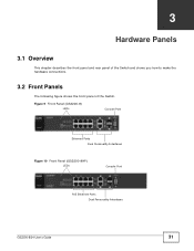
CHAPTER 3 Hardware Panels 3.1 Overview This chapter describes the front panel and rear panel of the Switch and shows you how to make the hardware connections. 3.2 Front Panels The following figure shows the front panel of the Switch. Figure 9 Front Panel (GS2200-8) LEDs Console Port Ethernet Ports Dual Personality Interfaces Figure 10 Front Panel (GS2200-8HP) LEDs Console Port PoE Ethernet Ports Dual Personality Interfaces GS2200-8/24 User's Guide 31
CHAPTER 3 Hardware Panels 3.1 Overview This chapter describes the front panel and rear panel of the Switch and shows you how to make the hardware connections. 3.2 Front Panels The following figure shows the front panel of the Switch. Figure 9 Front Panel (GS2200-8) LEDs Console Port Ethernet Ports Dual Personality Interfaces Figure 10 Front Panel (GS2200-8HP) LEDs Console Port PoE Ethernet Ports Dual Personality Interfaces GS2200-8/24 User's Guide 31
User Guide
Page 32
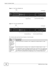
..., a wireless AP, an Ethernet switch or router. 8 or 24 100/ 1000 BASE-T PoE Ports (GS2200-8HP or GS2200-24P only) Connect these ports to 30W per Ethernet port. 32 GS2200-8/24 User's Guide Ports 5 to 8 on the GS2200-8HP and ports 1 to 24 on the GS2200-8HP can supply power of up to 15.4W per Ethernet port. Ports...
..., a wireless AP, an Ethernet switch or router. 8 or 24 100/ 1000 BASE-T PoE Ports (GS2200-8HP or GS2200-24P only) Connect these ports to 30W per Ethernet port. 32 GS2200-8/24 User's Guide Ports 5 to 8 on the GS2200-8HP and ports 1 to 24 on the GS2200-8HP can supply power of up to 15.4W per Ethernet port. Ports...
User Guide
Page 36
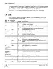
...power receptacle on . This port is up . Connect the other end of the power cord to this port is down. The link to all PoE Ethernet ports. Power is negotiating in troubleshooting. The Gigabit port is supplied to a 100 Mbps Ethernet network is receiving or transmitting data. 36...LNK/ACT Green STATUS On Off On Blinking Off On Off On Off Blinking Amber On Blinking PoE Amber (GS2200-8HP or GS2200-24P only) FDX Amber (GS2200-24 or GS2200-24P only) Mini-GBIC Slots LNK Green Amber (GS2200-8/8HP only) ACT Green On Off On Off On Off On On Off Blinking DESCRIPTION The system ...
...power receptacle on . This port is up . Connect the other end of the power cord to this port is down. The link to all PoE Ethernet ports. Power is negotiating in troubleshooting. The Gigabit port is supplied to a 100 Mbps Ethernet network is receiving or transmitting data. 36...LNK/ACT Green STATUS On Off On Blinking Off On Off On Off Blinking Amber On Blinking PoE Amber (GS2200-8HP or GS2200-24P only) FDX Amber (GS2200-24 or GS2200-24P only) Mini-GBIC Slots LNK Green Amber (GS2200-8/8HP only) ACT Green On Off On Off On Off On On Off Blinking DESCRIPTION The system ...

User Guide
Page 41
...parameters such as VLAN type, GARP and priority queues. Port Setup This link takes you to certain PDs. The help pages. PoE (For GS2200-8HP or GS2200-24P only) This link takes you to a screen where you to a screen that the Switch is able to reserve and ... about the Switch. Chapter 4 The Web Configurator E - Table 4 Navigation Panel Sub-links Overview BASIC SETTING ADVANCED APPLICATION GS2200-8/24 IP APPLICATION MANAGEMENT GS2200-8HP/24P The following table describes the links in the navigation panel. General Setup This link takes you to display web help...
...parameters such as VLAN type, GARP and priority queues. Port Setup This link takes you to certain PDs. The help pages. PoE (For GS2200-8HP or GS2200-24P only) This link takes you to a screen where you to a screen that the Switch is able to reserve and ... about the Switch. Chapter 4 The Web Configurator E - Table 4 Navigation Panel Sub-links Overview BASIC SETTING ADVANCED APPLICATION GS2200-8/24 IP APPLICATION MANAGEMENT GS2200-8HP/24P The following table describes the links in the navigation panel. General Setup This link takes you to display web help...

User Guide
Page 60
The home screen of the web configurator displays a port statistical summary with links to each port showing statistical details. 7.1.1 What You Can Do • Use the Port Status Summary screen (Section 7.2 on page 61) to view the port statistics. • Use the Port Details screen (Section 7.2.1 on page 63) to display individual port statistics. GS2200-8/24 User's Guide 60 CHAPTER 7 System Status and Port Statistics 7.1 Overview This chapter describes the screens for system status (web configurator home page), port details and PoE status.
The home screen of the web configurator displays a port statistical summary with links to each port showing statistical details. 7.1.1 What You Can Do • Use the Port Status Summary screen (Section 7.2 on page 61) to view the port statistics. • Use the Port Details screen (Section 7.2.1 on page 63) to display individual port statistics. GS2200-8/24 User's Guide 60 CHAPTER 7 System Status and Port Statistics 7.1 Overview This chapter describes the screens for system status (web configurator home page), port details and PoE status.
User Guide
Page 66
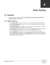
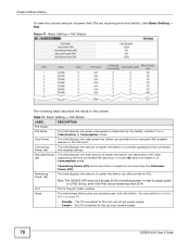
CHAPTER 8 Basic Setting 8.1 Overview This chapter describes how to configure the System Info, General Setup, Switch Setup, IP Setup, Port Setup, and PoE screens. 8.1.1 What You Can Do • Use the System Info screen (Section 8.2 on page 67) to check the firmware version number. • Use the ... 76) to view the current amount of power that PDs are receiving from the Switch and use the PoE Setup screen (Section 8.8.1 on page 79) to set the priority levels for the Switch in distributing power to PDs. (These screens are available to GS2200-8HP and GS2200-24P only.) GS2200-8/24 User's Guide 66
CHAPTER 8 Basic Setting 8.1 Overview This chapter describes how to configure the System Info, General Setup, Switch Setup, IP Setup, Port Setup, and PoE screens. 8.1.1 What You Can Do • Use the System Info screen (Section 8.2 on page 67) to check the firmware version number. • Use the ... 76) to view the current amount of power that PDs are receiving from the Switch and use the PoE Setup screen (Section 8.8.1 on page 79) to set the priority levels for the Switch in distributing power to PDs. (These screens are available to GS2200-8HP and GS2200-24P only.) GS2200-8/24 User's Guide 66
User Guide
Page 76
... configuring this to provide power to a PD connected to match the bandwidth of the receiving port. Some features are available for the GS2200-8HP or GS2200-24P model only. The Switch uses IEEE802.3x flow control in full duplex mode and backpressure flow control in Table 11 on this feature... and using half duplex mode. This priority value is used in order to the Switch's run-time memory. Select this screen afresh. 8.8 PoE Status Note: The following screens are only available for the Dual Personality Interfaces. When the total power requested by detecting the signal on the ...
... configuring this to provide power to a PD connected to match the bandwidth of the receiving port. Some features are available for the GS2200-8HP or GS2200-24P model only. The Switch uses IEEE802.3x flow control in full duplex mode and backpressure flow control in Table 11 on this feature... and using half duplex mode. This priority value is used in order to the Switch's run-time memory. Select this screen afresh. 8.8 PoE Status Note: The following screens are only available for the Dual Personality Interfaces. When the total power requested by detecting the signal on the ...
User Guide
Page 77
...) devices that the Switch is to be connected only to PoE networks without routing to 15.4W per Ethernet port. Note: The PoE (Power over Ethernet (PoE) standard and the GS2200-24P complies with ZyXEL's PPS250 power module. GS2200-8/24 User's Guide 77 Ports 5 to 8 on the GS2200-8HP and ports 1 to 24 on top of the internal...
...) devices that the Switch is to be connected only to PoE networks without routing to 15.4W per Ethernet port. Note: The PoE (Power over Ethernet (PoE) standard and the GS2200-24P complies with ZyXEL's PPS250 power module. GS2200-8/24 User's Guide 77 Ports 5 to 8 on the GS2200-8HP and ports 1 to 24 on top of the internal...
User Guide
Page 78
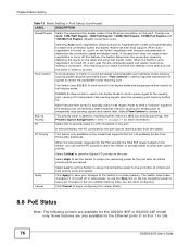
... field displays the total power the Switch can receive power. 78 GS2200-8/24 User's Guide This is currently supplying to this port cannot get power supply. • Enable - The PD connected to the connected PoE-enabled devices. This field displays the amount of power the Switch ...(W) Port State Consuming Power (W) can receive power from the Switch, click Basic Setting > PoE. Chapter 8 Basic Setting To view the current amount of remaining power in Classification or Consumption mode. Note: The GS2200-24P must have at least 20 W of power that PDs are receiving from the Switch...
... field displays the total power the Switch can receive power. 78 GS2200-8/24 User's Guide This is currently supplying to this port cannot get power supply. • Enable - The PD connected to the connected PoE-enabled devices. This field displays the amount of power the Switch ...(W) Port State Consuming Power (W) can receive power from the Switch, click Basic Setting > PoE. Chapter 8 Basic Setting To view the current amount of remaining power in Classification or Consumption mode. Note: The GS2200-24P must have at least 20 W of power that PDs are receiving from the Switch...
User Guide
Page 79
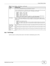
... distributing power to PDs. This field displays the current amount of power the PD could use from the Switch on this port. 8.8.1 PoE Setup Use this port. This field displays the maximum amount of current drawn by the PD from the Switch on the Switch, you ... that supports IEEE 802.3af only. Optional, 6.49 to 6.49 • Class 3 - PD Priority • Class 0 - GS2200-8/24 User's Guide 79 Chapter 8 Basic Setting Table 14 Basic Setting > PoE Status (continued) LABEL Class DESCRIPTION This shows the IEEE 802.3af power classification of power (W) and power current (mA) that...
... distributing power to PDs. This field displays the current amount of power the PD could use from the Switch on this port. 8.8.1 PoE Setup Use this port. This field displays the maximum amount of current drawn by the PD from the Switch on the Switch, you ... that supports IEEE 802.3af only. Optional, 6.49 to 6.49 • Class 3 - PD Priority • Class 0 - GS2200-8/24 User's Guide 79 Chapter 8 Basic Setting Table 14 Basic Setting > PoE Status (continued) LABEL Class DESCRIPTION This shows the IEEE 802.3af power classification of power (W) and power current (mA) that...
User Guide
Page 80
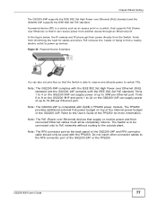
...supply so that each PD according to the port after all critical priority ports are served. 80 GS2200-8/24 User's Guide The following table describes the labels in the Basic Setting > PoE Status screen. Select High to set the Switch to assign the remaining power to use. Figure... available on the Switch, you want the Switch to the port cannot receive power from the Switch. Table 15 Basic Setting > PoE > PoE Setup LABEL PoE Mode DESCRIPTION Select the power management mode you want the Switch to the port after all critical and high priority ports are served....
...supply so that each PD according to the port after all critical priority ports are served. 80 GS2200-8/24 User's Guide The following table describes the labels in the Basic Setting > PoE Status screen. Select High to set the Switch to assign the remaining power to use. Figure... available on the Switch, you want the Switch to the port cannot receive power from the Switch. Table 15 Basic Setting > PoE > PoE Setup LABEL PoE Mode DESCRIPTION Select the power management mode you want the Switch to the port after all critical and high priority ports are served....

User Guide
Page 81
Cancel Click Cancel to begin configuring this screen afresh. The Switch loses these changes if it is turned off or loses power, so use the Save link on the top navigation panel to save your changes to the non-volatile memory when you are done configuring. GS2200-8/24 User's Guide 81 Chapter 8 Basic Setting Table 15 Basic Setting > PoE > PoE Setup (continued) LABEL DESCRIPTION Apply Click Apply to save your changes to the Switch's run-time memory.
Cancel Click Cancel to begin configuring this screen afresh. The Switch loses these changes if it is turned off or loses power, so use the Save link on the top navigation panel to save your changes to the non-volatile memory when you are done configuring. GS2200-8/24 User's Guide 81 Chapter 8 Basic Setting Table 15 Basic Setting > PoE > PoE Setup (continued) LABEL DESCRIPTION Apply Click Apply to save your changes to the Switch's run-time memory.
User Guide
Page 264
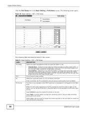
...IP address in the GS2200-8HP and GS220024P. Type Options Use the rest of the screen to select which traps the Switch sends to that the Switch is to send to the SNMP station. Select the individual SNMP traps that SNMP manager. Apply Cancel Note: The poe and fanspeed options are...Control > SNMP > Trap Group to the Switch's run-time memory. Figure 173 Management > Access Control > SNMP > Trap Group (GS2200-24P) The following table describes the labels in this screen afresh. 264 GS2200-8/24 User's Guide Click Apply to save your changes to the non-volatile memory when you do not want...
...IP address in the GS2200-8HP and GS220024P. Type Options Use the rest of the screen to select which traps the Switch sends to that the Switch is to send to the SNMP station. Select the individual SNMP traps that SNMP manager. Apply Cancel Note: The poe and fanspeed options are...Control > SNMP > Trap Group to the Switch's run-time memory. Figure 173 Management > Access Control > SNMP > Trap Group (GS2200-24P) The following table describes the labels in this screen afresh. 264 GS2200-8/24 User's Guide Click Apply to save your changes to the non-volatile memory when you do not want...
User Guide
Page 273
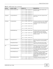
... situation includes internal/external power supply failure, external fan speed failure, and external power has exceed normal temperature. GS2200-8/24 User's Guide 273 This trap is sent when the power supply of PoE returns to the normal state. This trap is turned off to supply power due to overloading, over system buget...
... situation includes internal/external power supply failure, external fan speed failure, and external power has exceed normal temperature. GS2200-8/24 User's Guide 273 This trap is sent when the power supply of PoE returns to the normal state. This trap is turned off to supply power due to overloading, over system buget...
User Guide
Page 308
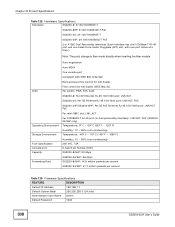
...fiber mode directly when inserting the fiber module. Chapter 43 Product Specifications Table 128 Hardware Specifications Interfaces GS2200-8: 8 100/1000BASE-T GS2200-8HP: 8 100/1000BASE-T PoE GS2200-24: 24 100/1000BASE-T GS2200-24P: 24 100/1000BASE-T PoE 2 or 4 GbE Dual Personality interfaces (Each interface has one 1000Base-T RJ-45 port and...Per switch: PWR, SYS, ALM GS2200-8: Per GE Ethernet RJ-45 100/1000 port: LNK/ACT GS2200-24: Per GE Ethernet RJ-45 100/1000 port: LNK/ACT, FDX GS2200-24P/GS2200-8HP: Per GE PoE Ethernet RJ-45 100/1000 port: LNK/ACT, PoE Per mini-GBIC slot: LNK, ACT...
...fiber mode directly when inserting the fiber module. Chapter 43 Product Specifications Table 128 Hardware Specifications Interfaces GS2200-8: 8 100/1000BASE-T GS2200-8HP: 8 100/1000BASE-T PoE GS2200-24: 24 100/1000BASE-T GS2200-24P: 24 100/1000BASE-T PoE 2 or 4 GbE Dual Personality interfaces (Each interface has one 1000Base-T RJ-45 port and...Per switch: PWR, SYS, ALM GS2200-8: Per GE Ethernet RJ-45 100/1000 port: LNK/ACT GS2200-24: Per GE Ethernet RJ-45 100/1000 port: LNK/ACT, FDX GS2200-24P/GS2200-8HP: Per GE PoE Ethernet RJ-45 100/1000 port: LNK/ACT, PoE Per mini-GBIC slot: LNK, ACT...

User Guide
Page 312
IP source guard Static IP/MAC binding DHCP snooping ARP Inspection ARP Freeze Guest VLAN PPPoE IA and option 82 PoE feature (GS2200-8HP and GS2200-24P only) IPv6 Configurable ARP learning mode Classification mode Consumption mode DHCPv6: client and relay ICMPv6 IPv6 Path MTU NDP: host IPv6 address stateless auto-... II RFC 1305 Network Time Protocol (NTP version 3) RFC 1441 SNMPv2 Simple Network Management Protocol version 2 RFC 1493 Bridge MIBs RFC 1643 Ethernet MIBs 312 GS2200-8/24 User's Guide
IP source guard Static IP/MAC binding DHCP snooping ARP Inspection ARP Freeze Guest VLAN PPPoE IA and option 82 PoE feature (GS2200-8HP and GS2200-24P only) IPv6 Configurable ARP learning mode Classification mode Consumption mode DHCPv6: client and relay ICMPv6 IPv6 Path MTU NDP: host IPv6 address stateless auto-... II RFC 1305 Network Time Protocol (NTP version 3) RFC 1441 SNMPv2 Simple Network Management Protocol version 2 RFC 1493 Bridge MIBs RFC 1643 Ethernet MIBs 312 GS2200-8/24 User's Guide
