
Service Manual
Page 4
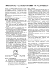
...SCARVES OR OTHER COVERINGS WHICH MIGHT OBSTRUCT VENTILATION. 4. WHILE SERVICING, USE AN ISOLATION TRANSFORMER FOR PROTECTION FROM A.C. VOLTAGE ACROSS THE COMBINATION OF 1500 OHM RESISTOR AND .15 MFD CAPACITOR. A.C. ETC PLACE THIS PROBE ON EACH EXPOSED METAL PART SUBJECT: GRAPHIC SYMBOLS ...SAFETY INFORMATION IN SERVICE LITERATURE. THE ONLY POTENTIAL SOURCE OF X-RAYS IN CURRENT T.V. EVERY TIME A COLOR CHASSIS IS SERVICED. WHEN TROUBLESHOOTING AND MAKING TEST MEASUREMENTS IN A PRODUCT WITH A PROBLEM OF EXCESSIVE HIGH VOLTAGE, AVOID BEING UNNECESSARILY CLOSE TO THE PICTURE TUBE AND...
...SCARVES OR OTHER COVERINGS WHICH MIGHT OBSTRUCT VENTILATION. 4. WHILE SERVICING, USE AN ISOLATION TRANSFORMER FOR PROTECTION FROM A.C. VOLTAGE ACROSS THE COMBINATION OF 1500 OHM RESISTOR AND .15 MFD CAPACITOR. A.C. ETC PLACE THIS PROBE ON EACH EXPOSED METAL PART SUBJECT: GRAPHIC SYMBOLS ...SAFETY INFORMATION IN SERVICE LITERATURE. THE ONLY POTENTIAL SOURCE OF X-RAYS IN CURRENT T.V. EVERY TIME A COLOR CHASSIS IS SERVICED. WHEN TROUBLESHOOTING AND MAKING TEST MEASUREMENTS IN A PRODUCT WITH A PROBLEM OF EXCESSIVE HIGH VOLTAGE, AVOID BEING UNNECESSARILY CLOSE TO THE PICTURE TUBE AND...
Service Manual
Page 12
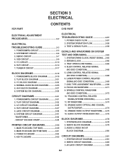
...BLOCK DIAGRAM 3-27 6. TU/IF CIRCUIT DIAGRAM 3-33 3. JACK CIRCUIT DIAGRAM 3-39 6. KEY P.C.BOARD 3-55 ELECTRICAL TROUBLESHOOTING GUIDE 3-57 1. LENS CONTROL RELATED SIGNAL (NO DISC CONDITION 3-68 6. DISC TYPE JUDGEMENT WAVEFORM.........3-69 8. TRACKING CONTROL ...(NO DISC CONDITION 3-68 5. RF WAVEFORM 3-74 12. AV/JACK CIRCUIT DIAGRAM 3-85 3-1 SECTION 3 ELECTRICAL VCR PART CONTENTS DVD PART ELECTRICAL ADJUSTMENT PROCEDURES 3-2 ELECTRICAL TROUBLESHOOTING GUIDE 3-3 1. POWER(SMPS) CIRCUIT 3-3 2. SYSTEM/KEY CIRCUIT 3-6 3. TU/IF BLOCK DIAGRAM 3-21 3. NORMAL...
...BLOCK DIAGRAM 3-27 6. TU/IF CIRCUIT DIAGRAM 3-33 3. JACK CIRCUIT DIAGRAM 3-39 6. KEY P.C.BOARD 3-55 ELECTRICAL TROUBLESHOOTING GUIDE 3-57 1. LENS CONTROL RELATED SIGNAL (NO DISC CONDITION 3-68 6. DISC TYPE JUDGEMENT WAVEFORM.........3-69 8. TRACKING CONTROL ...(NO DISC CONDITION 3-68 5. RF WAVEFORM 3-74 12. AV/JACK CIRCUIT DIAGRAM 3-85 3-1 SECTION 3 ELECTRICAL VCR PART CONTENTS DVD PART ELECTRICAL ADJUSTMENT PROCEDURES 3-2 ELECTRICAL TROUBLESHOOTING GUIDE 3-3 1. POWER(SMPS) CIRCUIT 3-3 2. SYSTEM/KEY CIRCUIT 3-6 3. TU/IF BLOCK DIAGRAM 3-21 3. NORMAL...

Service Manual
Page 14
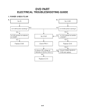
YES NO Is BD101 Normal? YES NO Is D124 Normal? YES NO Is D123 normal? ELECTRICAL TROUBLESHOOTING GUIDE 1. Replace FR101 (Use the same ICW) Replace BD101 YES NO Is R101 Normal? YES NO Are D125 normal? Replace D125 Check or Replace D102 Is there about 2.5V NO at IC103 Pin1? YES NO Is D121 Normal? YES Power Line of Main PCB is short Replace IC103 Replace D123 Replace D124 Replace D121 3-3 NO Is D102 normal? Power(SMPS) CIRCUIT (1) No 5.3VA No 5.3VA YES Is the FR101 NO Normal? NO plied to IC101 Pin2? Replace R101 YES Is Vcc (9V - 18V) sup-
YES NO Is BD101 Normal? YES NO Is D124 Normal? YES NO Is D123 normal? ELECTRICAL TROUBLESHOOTING GUIDE 1. Replace FR101 (Use the same ICW) Replace BD101 YES NO Is R101 Normal? YES NO Are D125 normal? Replace D125 Check or Replace D102 Is there about 2.5V NO at IC103 Pin1? YES NO Is D121 Normal? YES Power Line of Main PCB is short Replace IC103 Replace D123 Replace D124 Replace D121 3-3 NO Is D102 normal? Power(SMPS) CIRCUIT (1) No 5.3VA No 5.3VA YES Is the FR101 NO Normal? NO plied to IC101 Pin2? Replace R101 YES Is Vcc (9V - 18V) sup-

Service Manual
Page 17
... the Q165 Power Circuit. (2) The unstable loading of a Cassette tape The unstable loading of the CST ? Check the Drum Motor signal. Refer to SMPS 5.3VA troubleshooting. Is 5V applied to PMC01 NO Pin1? Does 5V appear at IC501 Pin18? YES Does the "L" signal appear at IC501 Pin80? NO YES Check the...
... the Q165 Power Circuit. (2) The unstable loading of a Cassette tape The unstable loading of the CST ? Check the Drum Motor signal. Refer to SMPS 5.3VA troubleshooting. Is 5V applied to PMC01 NO Pin1? Does 5V appear at IC501 Pin18? YES Does the "L" signal appear at IC501 Pin80? NO YES Check the...
Service Manual
Page 50
NO Is 3.4VA section working ? POWER CHECK FLOW A. NO Is 3.4VA section working ? YES NO Is 3.4V present at emitter of Q126? YES NO Check D105/D106/D107/ D108 and replace. 3-57 YES Is 5.6V present at Cathode of D105 or D107? NO Replace IC101. YES Replace Q126. YES Replace Q121. No 3.4VA. No 3.4VA Check FR101 Is there a DC voltage at collector of Q121? DVD PART ELECTRICAL TROUBLESHOOTING GUIDE 1. No 5V B.
NO Is 3.4VA section working ? POWER CHECK FLOW A. NO Is 3.4VA section working ? YES NO Is 3.4V present at emitter of Q126? YES NO Check D105/D106/D107/ D108 and replace. 3-57 YES Is 5.6V present at Cathode of D105 or D107? NO Replace IC101. YES Replace Q126. YES Replace Q121. No 3.4VA. No 3.4VA Check FR101 Is there a DC voltage at collector of Q121? DVD PART ELECTRICAL TROUBLESHOOTING GUIDE 1. No 5V B.
Service Manual
Page 78
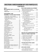
... 4-9 27.Plate Slider 4-9 28.Lever Tension 4-9 29.Lever Spring 4-9 30. X-distance Adjustment 4-17 7. SECTION 4 MECHANISM OF VCR PART(D-37) CONTENTS DECK MECHANISM PARTS LOCATIONS • Top View 4-1 • Bottom View 4-1 DISASSEMBLY AND ASSEMBLY OF DECK MECHANISM ... Front Loading Mechanism Section...........4-28 2. Guide Roller Height Adjustment 4-15 4-1. Regular Check and Repair 4-20 4. Grease Application 4-21 TROUBLESHOOTING GUIDE 1. Mechanism Assembly Mode Check ........4-13 2. Maintenance Process 4-20 5-1. Audio, RF Normalization Time (Locking Time) Check in ...
... 4-9 27.Plate Slider 4-9 28.Lever Tension 4-9 29.Lever Spring 4-9 30. X-distance Adjustment 4-17 7. SECTION 4 MECHANISM OF VCR PART(D-37) CONTENTS DECK MECHANISM PARTS LOCATIONS • Top View 4-1 • Bottom View 4-1 DISASSEMBLY AND ASSEMBLY OF DECK MECHANISM ... Front Loading Mechanism Section...........4-28 2. Guide Roller Height Adjustment 4-15 4-1. Regular Check and Repair 4-20 4. Grease Application 4-21 TROUBLESHOOTING GUIDE 1. Mechanism Assembly Mode Check ........4-13 2. Maintenance Process 4-20 5-1. Audio, RF Normalization Time (Locking Time) Check in ...

Service Manual
Page 101
... supply to the Capstan Motor Vcc1, Vcc2.? YES NO Replace End sensor. Is the voltage across IR LED between 0.8~1.5V? YES Check syscon circuit. MECHANISM TROUBLESHOOTING GUIDE 1.Deck Mechanism A. Check the syscon power. B. voltage of Capstan Motor supply side more than 3.5V "L": less than 4V? YES Check syscon circuit. YES Is...
... supply to the Capstan Motor Vcc1, Vcc2.? YES NO Replace End sensor. Is the voltage across IR LED between 0.8~1.5V? YES Check syscon circuit. MECHANISM TROUBLESHOOTING GUIDE 1.Deck Mechanism A. Check the syscon power. B. voltage of Capstan Motor supply side more than 3.5V "L": less than 4V? YES Check syscon circuit. YES Is...

Service Manual
Page 102
.... Is there variation for CST IN S/W Output? (In Tape with the capstan shaft. YES Check the Syscon, µ-COM. NO Replace CST IN S/W. 4-24 D. MECHANISM TROUBLESHOOTING GUIDE C. YES Are there T/up and supply reel pulses. YES NO Check CST Holder Assembly. In Play/Cue/Rev is the pinch roller in contact...
.... Is there variation for CST IN S/W Output? (In Tape with the capstan shaft. YES Check the Syscon, µ-COM. NO Replace CST IN S/W. 4-24 D. MECHANISM TROUBLESHOOTING GUIDE C. YES Are there T/up and supply reel pulses. YES NO Check CST Holder Assembly. In Play/Cue/Rev is the pinch roller in contact...

Service Manual
Page 103
... Reel Sensors ok? NO NO Is the Vcc voltage of the Drum Motor more than 2.3V? NO YES Replace the Belt. Check Servo, Power. MECHANISM TROUBLESHOOTING GUIDE E. YES Check Servo, Syscon. Check Syscon, Circuit. 4-25 Replace the Drum Motor. NO NO Check Alignment positions (page 4-14) Is the Belt ok? Is...
... Reel Sensors ok? NO NO Is the Vcc voltage of the Drum Motor more than 2.3V? NO YES Replace the Belt. Check Servo, Power. MECHANISM TROUBLESHOOTING GUIDE E. YES Check Servo, Syscon. Check Syscon, Circuit. 4-25 Replace the Drum Motor. NO NO Check Alignment positions (page 4-14) Is the Belt ok? Is...

Service Manual
Page 104
... 5V?? Replace or add the Lever Assembly Switch Spring. Does the Lever Assembly Switch work? YES NO NO Check syscon circuit. Check power circuit. MECHANISM TROUBLESHOOTING GUIDE 2. Does the L/D motor rotate in reverse?
... 5V?? Replace or add the Lever Assembly Switch Spring. Does the Lever Assembly Switch work? YES NO NO Check syscon circuit. Check power circuit. MECHANISM TROUBLESHOOTING GUIDE 2. Does the L/D motor rotate in reverse?

Service Manual
Page 105
... the F/L Rear Rack. Cassette will not load. YES NO Does the Door Opener work ? Is the Door opener assembled correctly? Does the CST insert? MECHANISM TROUBLESHOOTING GUIDE C. Check the power of L/D Motor. YES NO Does the F/L Arm Assembly work ? YES NO Replace the Front Loading Mechanism Assembly. 4-27 Replace the Lid...
... the F/L Rear Rack. Cassette will not load. YES NO Does the Door Opener work ? Is the Door opener assembled correctly? Does the CST insert? MECHANISM TROUBLESHOOTING GUIDE C. Check the power of L/D Motor. YES NO Does the F/L Arm Assembly work ? YES NO Replace the Front Loading Mechanism Assembly. 4-27 Replace the Lid...