
Service Manual
Page 1
SERVICE MANUAL MODEL : XBV613 SERVICE MANUAL Product Type: VCR+DVD COMBI Chassis: D37 + DP-10C Manual Series: XBV613 Manual Part #: 3829RGN005G Model Line: D Product Year: 2006 Model Series: XBV613 Printed in U.S.A CONTENTS SUMMARY 1 CABINET & MAIN CHASSIS 2 ELECTRICAL 3 MECHANISM OF VCR PART 4 REPLACEMENT PARTS LIST 5 Published March 2006 by Technical Publications Zenith Electronics Corporation 201 James Record Road Huntsville, Alabama 35824-1513 Copyright © 2006 by Zenith Electronics Corporation
SERVICE MANUAL MODEL : XBV613 SERVICE MANUAL Product Type: VCR+DVD COMBI Chassis: D37 + DP-10C Manual Series: XBV613 Manual Part #: 3829RGN005G Model Line: D Product Year: 2006 Model Series: XBV613 Printed in U.S.A CONTENTS SUMMARY 1 CABINET & MAIN CHASSIS 2 ELECTRICAL 3 MECHANISM OF VCR PART 4 REPLACEMENT PARTS LIST 5 Published March 2006 by Technical Publications Zenith Electronics Corporation 201 James Record Road Huntsville, Alabama 35824-1513 Copyright © 2006 by Zenith Electronics Corporation
Service Manual
Page 4
...COMPONENTS SUCH AS FUSES, FLAMEPROOF RESISTORS, CAPACITORS, ETC. AFTER RE-ASSEMBLY OF THE SET ALWAYS PERFORM AN A.C. LEAKAGE TEST ON ALL EXPOSED METALLIC PARTS OF THE CABINET, (THE CHANNEL SELECTOR KNOB, ANTENNA TERMINALS. CONDUIT. THE EXCLAMATION POINT WITHIN AN EQUILATERAL TRIANGLE IS INTENDED TO ALERT THE SERVICE PERSONNEL... MODIFICATIONS. 7. SOLDERING MUST BE INSPECTED TO DISCOVER POSSIBLE COLD SOLDER JOINTS, SOLDER SPLASHES OR SHARP SOLDER POINTS. VOLTAGE ACROSS THE COMBINATION OF 1500 OHM RESISTOR AND .15 MFD CAPACITOR. VOLTAGE MEASUREMENTS FOR EACH EXPOSED METALLIC...
...COMPONENTS SUCH AS FUSES, FLAMEPROOF RESISTORS, CAPACITORS, ETC. AFTER RE-ASSEMBLY OF THE SET ALWAYS PERFORM AN A.C. LEAKAGE TEST ON ALL EXPOSED METALLIC PARTS OF THE CABINET, (THE CHANNEL SELECTOR KNOB, ANTENNA TERMINALS. CONDUIT. THE EXCLAMATION POINT WITHIN AN EQUILATERAL TRIANGLE IS INTENDED TO ALERT THE SERVICE PERSONNEL... MODIFICATIONS. 7. SOLDERING MUST BE INSPECTED TO DISCOVER POSSIBLE COLD SOLDER JOINTS, SOLDER SPLASHES OR SHARP SOLDER POINTS. VOLTAGE ACROSS THE COMBINATION OF 1500 OHM RESISTOR AND .15 MFD CAPACITOR. VOLTAGE MEASUREMENTS FOR EACH EXPOSED METALLIC...
Service Manual
Page 5
...aluminum foil, to prevent electrostatic charge buildup or exposure of your foot from a carpeted floor can be damaged easily by this VCR+DVD or any of typical ES devices are called Electrostatically Sensitive (ES) Devices. Remembers Safety First: General Servicing Precautions 1. trolytic...should be removed for potential shock reasons prior to applying power to solder or unsolder ES devices. 4. Note 1 : Accessible Conductive Parts including Metal panels, Input terminals, Earphone jacks, etc. Electrostatically Sensitive (ES) Devices Some semiconductor (solid state) devices can generate...
...aluminum foil, to prevent electrostatic charge buildup or exposure of your foot from a carpeted floor can be damaged easily by this VCR+DVD or any of typical ES devices are called Electrostatically Sensitive (ES) Devices. Remembers Safety First: General Servicing Precautions 1. trolytic...should be removed for potential shock reasons prior to applying power to solder or unsolder ES devices. 4. Note 1 : Accessible Conductive Parts including Metal panels, Input terminals, Earphone jacks, etc. Electrostatically Sensitive (ES) Devices Some semiconductor (solid state) devices can generate...
Service Manual
Page 12
... ...........3-76 BLOCK DIAGRAMS 3-78 1. SERVO BLOCK DIAGRAM 3-79 3. HI-FI BLOCK DIAGRAM 3-27 6. AUDIO & VIDEO IN/OUT BLOCK DIAGRAM 3-80 CIRCUIT DIAGRAMS 3-81 1. SECTION 3 ELECTRICAL VCR PART CONTENTS DVD PART ELECTRICAL ADJUSTMENT PROCEDURES 3-2 ELECTRICAL TROUBLESHOOTING GUIDE 3-3 1. SERVO CIRCUIT 3-7 4. NORMAL AUDIO BLOCK DIAGRAM 3-25 5. SYSTEM BLOCK DIAGRAM 3-29 CIRCUIT DIAGRAMS 3-31 1. JACK CIRCUIT DIAGRAM 3-39...
... ...........3-76 BLOCK DIAGRAMS 3-78 1. SERVO BLOCK DIAGRAM 3-79 3. HI-FI BLOCK DIAGRAM 3-27 6. AUDIO & VIDEO IN/OUT BLOCK DIAGRAM 3-80 CIRCUIT DIAGRAMS 3-81 1. SECTION 3 ELECTRICAL VCR PART CONTENTS DVD PART ELECTRICAL ADJUSTMENT PROCEDURES 3-2 ELECTRICAL TROUBLESHOOTING GUIDE 3-3 1. SERVO CIRCUIT 3-7 4. NORMAL AUDIO BLOCK DIAGRAM 3-25 5. SYSTEM BLOCK DIAGRAM 3-29 CIRCUIT DIAGRAMS 3-31 1. JACK CIRCUIT DIAGRAM 3-39...
Service Manual
Page 13
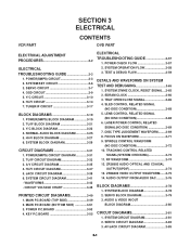
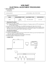
... the Front Panel the same time, then it goes in to Tracking initial mode. b) Connect the CH1 of CH2 to the Video Out for the VCR. c) Trigger the mixed Combo Video Signal of the oscilloscope to the H/SW(TP) and CH2 to the CH1 H/SW(TP) and then check the distance...) OSCILLOSCOPE CH1 CH2 R/C KEY • WAVEFORM H/SW V.out (TP) H/SW Composite VIDEO 6.5H(412µs) 3-2 Note - c-3) Repeat the above step(No.b-2), then PG adjusts automatically. VCR PART ELECTRICAL ADJUSTMENT PROCEDURES 1.
... the Front Panel the same time, then it goes in to Tracking initial mode. b) Connect the CH1 of CH2 to the Video Out for the VCR. c) Trigger the mixed Combo Video Signal of the oscilloscope to the H/SW(TP) and CH2 to the CH1 H/SW(TP) and then check the distance...) OSCILLOSCOPE CH1 CH2 R/C KEY • WAVEFORM H/SW V.out (TP) H/SW Composite VIDEO 6.5H(412µs) 3-2 Note - c-3) Repeat the above step(No.b-2), then PG adjusts automatically. VCR PART ELECTRICAL ADJUSTMENT PROCEDURES 1.

Service Manual
Page 24
... mode Is brightness normal? NO plied to IC301 NO Pins23, 44, 45, 68, 77? Check the SW 5V power. YES Replace IC301. 3-13 Check system part (V.H/SW) Check the drum *OPTION Pins72, 73, 74(SP) Pins65, 66, 67(EP) 3. NO YES Is the brightness signal sup- YES Does the FM signal...? YES Does signal appear at IC301 Pins73(SP)/ NO 66(EP)? NO YES Check the power of Pins23, 44, 45, 52, 68, 77. Check system part Check X301. YES Check the SW 5V power Is Y/C Bus applied to NO IC301 Pin57? YES YES Is color normal? A Check X301 oscillation frequency. A YES...
... mode Is brightness normal? NO plied to IC301 NO Pins23, 44, 45, 68, 77? Check the SW 5V power. YES Replace IC301. 3-13 Check system part (V.H/SW) Check the drum *OPTION Pins72, 73, 74(SP) Pins65, 66, 67(EP) 3. NO YES Is the brightness signal sup- YES Does the FM signal...? YES Does signal appear at IC301 Pins73(SP)/ NO 66(EP)? NO YES Check the power of Pins23, 44, 45, 52, 68, 77. Check system part Check X301. YES Check the SW 5V power Is Y/C Bus applied to NO IC301 Pin57? YES YES Is color normal? A Check X301 oscillation frequency. A YES...

Service Manual
Page 26
.... NO (IC801 Pin39) and the Tape quality. YES Is the RF Envelope at NO IC801 Pin80(L-CH), 78(R-CH)? Check IC501 Pin19 (A.H/SW) Check the parts of IC801 NO (Pins3, 5, 15, 32, 36, 46, 54). Y/C CIRCUIT (2) Hi-Fi Playback PB mode YES No Sound. Check the Jack(JK901) YES Check C801...
.... NO (IC801 Pin39) and the Tape quality. YES Is the RF Envelope at NO IC801 Pin80(L-CH), 78(R-CH)? Check IC501 Pin19 (A.H/SW) Check the parts of IC801 NO (Pins3, 5, 15, 32, 36, 46, 54). Y/C CIRCUIT (2) Hi-Fi Playback PB mode YES No Sound. Check the Jack(JK901) YES Check C801...
Service Manual
Page 36
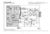
... INTO THE SET IS NOT DELAYED UNTIL THE NEW SERVICE LITERATURE IS PRINTED. NOTE) NOTE) NOTE) NOTE) Warning Parts that are shaded are DC-measured with specified part number. 2. SPECIAL COMPONENTS ARE SHADED ON THE SCHEMATIC FOR EASY IDENTIFICATION. Shaded( ) parts are critical for safety. NOTES) Symbol denotes DC chassis ground. CIRCUIT DIAGRAMS 1.
... INTO THE SET IS NOT DELAYED UNTIL THE NEW SERVICE LITERATURE IS PRINTED. NOTE) NOTE) NOTE) NOTE) Warning Parts that are shaded are DC-measured with specified part number. 2. SPECIAL COMPONENTS ARE SHADED ON THE SCHEMATIC FOR EASY IDENTIFICATION. Shaded( ) parts are critical for safety. NOTES) Symbol denotes DC chassis ground. CIRCUIT DIAGRAMS 1.

Service Manual
Page 47
POWER P.C.BOARD LOCATION GUIDE NOTES) NOTES) NOTES) NOTES) Warning Parts that are shaded are critical With respect to risk of fire or electricial shock. 3-53 3-54 3.
POWER P.C.BOARD LOCATION GUIDE NOTES) NOTES) NOTES) NOTES) Warning Parts that are shaded are critical With respect to risk of fire or electricial shock. 3-53 3-54 3.
Service Manual
Page 50
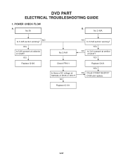
No 5V B. YES Is 5.6V present at Cathode of D105 or D107? NO Replace IC101. NO Is 3.4VA section working ? NO Is 3.4VA section working ? YES Replace Q126. No 3.4VA Check FR101 Is there a DC voltage at collector of Q121? YES Replace Q121. DVD PART ELECTRICAL TROUBLESHOOTING GUIDE 1. No 3.4VA. POWER CHECK FLOW A. YES NO Is 3.4V present at emitter of Q126? YES NO Check D105/D106/D107/ D108 and replace. 3-57
No 5V B. YES Is 5.6V present at Cathode of D105 or D107? NO Replace IC101. NO Is 3.4VA section working ? NO Is 3.4VA section working ? YES Replace Q126. No 3.4VA Check FR101 Is there a DC voltage at collector of Q121? YES Replace Q121. DVD PART ELECTRICAL TROUBLESHOOTING GUIDE 1. No 3.4VA. POWER CHECK FLOW A. YES NO Is 3.4V present at emitter of Q126? YES NO Check D105/D106/D107/ D108 and replace. 3-57
Service Manual
Page 78
... Adjustment 4-15 4-2. Fine Adjustment (Azimuth Adjustment 4-17 6. Essential Check and Repair 4-20 3. Maintenance Process 4-20 5-1. Front Loading Mechanism Section...........4-28 2. SECTION 4 MECHANISM OF VCR PART(D-37) CONTENTS DECK MECHANISM PARTS LOCATIONS • Top View 4-1 • Bottom View 4-1 DISASSEMBLY AND ASSEMBLY OF DECK MECHANISM 01.Disassembly of Drum assembly 4-2 02.Disassembly of Plate top...
... Adjustment 4-15 4-2. Fine Adjustment (Azimuth Adjustment 4-17 6. Essential Check and Repair 4-20 3. Maintenance Process 4-20 5-1. Front Loading Mechanism Section...........4-28 2. SECTION 4 MECHANISM OF VCR PART(D-37) CONTENTS DECK MECHANISM PARTS LOCATIONS • Top View 4-1 • Bottom View 4-1 DISASSEMBLY AND ASSEMBLY OF DECK MECHANISM 01.Disassembly of Drum assembly 4-2 02.Disassembly of Plate top...

Service Manual
Page 79
...the procedure in the reverse order. (1) When reassembling, confirm Mechanism and Mode Switch Alignment Position (2) When disassembling, the Parts in the "Starting No." Fixing Type 1 Drum Assembly 3 screws 2 Plate Top 2 hooks 2 3 Holder Assembly ...33 Base Loading 3 Hooks 2,3,14 34 Base Tension Chassis Embossing 35 Arm Assembly Idler Jog Locking Tab Ref. column should be removed first." 4-1 Procedure Starting Part No. Posi Draw- tion ings A-1 T A-2 T A-2 T A-2 T A-2 T A-2 T A-2 T A-3 T A-3 T A-3 T A-3 T A-3 T A-4 T A-4 T A-4 T A-5 T A-5 T A-5 T A-5 T A-6 B A-6 B A-6 B A-6...
...the procedure in the reverse order. (1) When reassembling, confirm Mechanism and Mode Switch Alignment Position (2) When disassembling, the Parts in the "Starting No." Fixing Type 1 Drum Assembly 3 screws 2 Plate Top 2 hooks 2 3 Holder Assembly ...33 Base Loading 3 Hooks 2,3,14 34 Base Tension Chassis Embossing 35 Arm Assembly Idler Jog Locking Tab Ref. column should be removed first." 4-1 Procedure Starting Part No. Posi Draw- tion ings A-1 T A-2 T A-2 T A-2 T A-2 T A-2 T A-2 T A-3 T A-3 T A-3 T A-3 T A-3 T A-4 T A-4 T A-4 T A-5 T A-5 T A-5 T A-5 T A-6 B A-6 B A-6 B A-6...

Service Manual
Page 82
...with pointed or flat end) CAUTIONS Assemble while pressing the (C), (C') part after firstly inserting the (E) part of the holder assembly CST into the groove on the (E') part of chassis. 4-4 A-2-5) 1) Firstly separate the left part of the arm assembly F/L from the groove of chassis while pushing the...Disassembly of Plate Top (Fig. Opener Door (Fig. Disassembly of Gear Assembly Rack F/L (Fig. CAUTIONS For the assembly, correspond the gear part of chassis while moving the gear assembly rack F/L toward the arrow (A) direction. 2) Separate the gear assembly rack F/L toward the arrow (B)...
...with pointed or flat end) CAUTIONS Assemble while pressing the (C), (C') part after firstly inserting the (E) part of the holder assembly CST into the groove on the (E') part of chassis. 4-4 A-2-5) 1) Firstly separate the left part of the arm assembly F/L from the groove of chassis while pushing the...Disassembly of Plate Top (Fig. Opener Door (Fig. Disassembly of Gear Assembly Rack F/L (Fig. CAUTIONS For the assembly, correspond the gear part of chassis while moving the gear assembly rack F/L toward the arrow (A) direction. 2) Separate the gear assembly rack F/L toward the arrow (B)...

Service Manual
Page 83
... up while turning it up . 4-5 A-3-1 from the embossing of the chassis (S4) and step backward, and disassemble it while holding it upward. 10. A-3-4) 1) Separate the (A) part of the head F/E from the embossing of Fig. Motor Assembly L/D (Fig. Gear Wheel (Fig. Base Assembly A/C Head (Fig. A-3-1) 1) Take the connector (C1) connected to the...
... up while turning it up . 4-5 A-3-1 from the embossing of the chassis (S4) and step backward, and disassemble it while holding it upward. 10. A-3-4) 1) Separate the (A) part of the head F/E from the embossing of Fig. Motor Assembly L/D (Fig. Gear Wheel (Fig. Base Assembly A/C Head (Fig. A-3-1) 1) Take the connector (C1) connected to the...

Service Manual
Page 85
... P4 up while turning it anti-clockwise. 17. REVERSE THE MECHANISM. 4-7 DISASSEMBLY AND ASSEMBLY OF DECK MECHANISM Opener Lid (Fig. A-5-2) 1) Release the (B) part of the opener lid from the embossing of chassis. 2) Disassemble the opener lid upward while turning it upward. A-5 16. Arm T/up . 19. A-5-4) ...Chassis Fig. A-5-4) 1) Turn the arm T/up (Fig. CAUTIONS For the assembly, check the (C) part of chassis and then hold it anticlockwise. 18. A-5-3) (C) Base Assembly P4 (Fig. A-5-1) (A) (C) (H9) Arm T/up to release the anchor jaw (H9...
... P4 up while turning it anti-clockwise. 17. REVERSE THE MECHANISM. 4-7 DISASSEMBLY AND ASSEMBLY OF DECK MECHANISM Opener Lid (Fig. A-5-2) 1) Release the (B) part of the opener lid from the embossing of chassis. 2) Disassemble the opener lid upward while turning it upward. A-5 16. Arm T/up . 19. A-5-4) ...Chassis Fig. A-5-4) 1) Turn the arm T/up (Fig. CAUTIONS For the assembly, check the (C) part of chassis and then hold it anticlockwise. 18. A-5-3) (C) Base Assembly P4 (Fig. A-5-1) (A) (C) (H9) Arm T/up to release the anchor jaw (H9...

Service Manual
Page 87
.... A-7-6) (B) Lever spring (Fig. A-7-1)/ Gear Cam (Fig. A-7-3) 1) Release the hook (H11) of the plate slider and then disassemble it up . 29. Lever Tension (Fig. A-7-7) 1) Release the (B) part of the lever spring from the guide (A) of the gear cam and then disassemble it up . 28. A-7-3) Brake Assembly Capstan (Fig. A-7 24. Plate Slider (Fig...
.... A-7-6) (B) Lever spring (Fig. A-7-1)/ Gear Cam (Fig. A-7-3) 1) Release the hook (H11) of the plate slider and then disassemble it up . 29. Lever Tension (Fig. A-7-7) 1) Release the (B) part of the lever spring from the guide (A) of the gear cam and then disassemble it up . 28. A-7-3) Brake Assembly Capstan (Fig. A-7 24. Plate Slider (Fig...

Service Manual
Page 89
A-9-2) (B) (C) Chassis (D) Fig. Arm assembly Idler Jog (Fig. A-9-1) (A) Arm Assembly Idler Jog (Fig. A-9-2 toward the arrow direction. 2) Disassemble the arm assembly idler upward. A-9-2) 1) Push both (B), (C) parts in disassembly. 4-11 CAUTIONS Take care to ensure that the (D) part in the drawing is not hung to chassis in Fig. Base Tension (Fig. A-9 34. A-9-1) 1) Release the (A) part of the base tension from the embossing of chassis. 2) Hold the base tension upward while turning it anti-clockwise. 35. DISASSEMBLY AND ASSEMBLY OF DECK MECHANISM Base Tension (Fig.
A-9-2) (B) (C) Chassis (D) Fig. Arm assembly Idler Jog (Fig. A-9-1) (A) Arm Assembly Idler Jog (Fig. A-9-2 toward the arrow direction. 2) Disassemble the arm assembly idler upward. A-9-2) 1) Push both (B), (C) parts in disassembly. 4-11 CAUTIONS Take care to ensure that the (D) part in the drawing is not hung to chassis in Fig. Base Tension (Fig. A-9 34. A-9-1) 1) Release the (A) part of the base tension from the embossing of chassis. 2) Hold the base tension upward while turning it anti-clockwise. 35. DISASSEMBLY AND ASSEMBLY OF DECK MECHANISM Base Tension (Fig.

Service Manual
Page 90
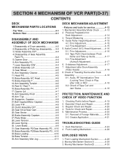
S 300 250 200 0 50 1V5HM0TTCE-O3ATR0ES3QVRSIUESDETERTOEK SRK - V H T 0- Post height adjusting driver 6. + Type driver (ø5) Part No:DTL-0005 4-12 Torque gauge 600g.Cm ATG Part No:D00-D002 4. Cassette Torque Meter SRK-VHT-303(Not SVC part) Part No:D00-D006 2. Torque gauge adaptor Part No:D09-R001 5. DECK MECHANISM ADJUSTMENT • Fixtures and Tools for Service 1. T 50 100 150 200 250 300 3. Alignment tape Part No NTSC:DTN-0001 PAL:DTN-0002 SRK -VH T-
S 300 250 200 0 50 1V5HM0TTCE-O3ATR0ES3QVRSIUESDETERTOEK SRK - V H T 0- Post height adjusting driver 6. + Type driver (ø5) Part No:DTL-0005 4-12 Torque gauge 600g.Cm ATG Part No:D00-D002 4. Cassette Torque Meter SRK-VHT-303(Not SVC part) Part No:D00-D006 2. Torque gauge adaptor Part No:D09-R001 5. DECK MECHANISM ADJUSTMENT • Fixtures and Tools for Service 1. T 50 100 150 200 250 300 3. Alignment tape Part No NTSC:DTN-0001 PAL:DTN-0002 SRK -VH T-
Service Manual
Page 92
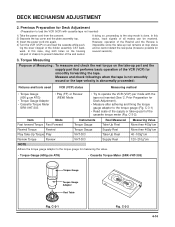
.... 2) Separate the top cover and the plate assembly top. 3) Insert the power cord into again. 4) Turn the VCR (VCP) on the housing rail part of chassis to prevent detection of the VCR (VCP) for several seconds). 3. C-3-2 4-14 C-3-2). S 300 250 200 0 50 1V5HM0TTCE-O3ATR0ES3QVRSIUESDETERTOEK SRK - ing the...torque gauge (Fig. If doing so, proceeding to load the VCR (VCP) with the tape not inserted (See '2. However, operation of the Rewind and the Review is impossible since the take -up part and the supply part that performs basic operation of the end sensor. C-3-1 SRK -VH...
.... 2) Separate the top cover and the plate assembly top. 3) Insert the power cord into again. 4) Turn the VCR (VCP) on the housing rail part of chassis to prevent detection of the VCR (VCP) for several seconds). 3. C-3-2 4-14 C-3-2). S 300 250 200 0 50 1V5HM0TTCE-O3ATR0ES3QVRSIUESDETERTOEK SRK - ing the...torque gauge (Fig. If doing so, proceeding to load the VCR (VCP) with the tape not inserted (See '2. However, operation of the Rewind and the Review is impossible since the take -up part and the supply part that performs basic operation of the end sensor. C-3-1 SRK -VH...
Service Manual
Page 93
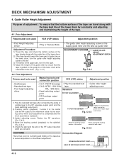
...4-15 DECK MECHANISM ADJUSTMENT 4. C-4-2) 4) Move the tracking control (playback) to the right/left 3) If it travels to the upper part, turn the guide roller height adjusting screw to the maximum value via the tracking control when such adjustment is completed after the drum assembly.... 4-1. Prior Adjustment Fixtures and tools used • Oscilloscope • Standard test tape • Post height adjusting driver Measuring tools and connection position VCR (VCP) status • CH-1: PB RF Envelope • Play the standard test • CH-2: NTSC : SW 30Hz tape. C-4-2 CAUTIONS...
...4-15 DECK MECHANISM ADJUSTMENT 4. C-4-2) 4) Move the tracking control (playback) to the right/left 3) If it travels to the upper part, turn the guide roller height adjusting screw to the maximum value via the tracking control when such adjustment is completed after the drum assembly.... 4-1. Prior Adjustment Fixtures and tools used • Oscilloscope • Standard test tape • Post height adjusting driver Measuring tools and connection position VCR (VCP) status • CH-1: PB RF Envelope • Play the standard test • CH-2: NTSC : SW 30Hz tape. C-4-2 CAUTIONS...