Service Manual
Page 2
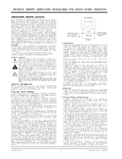
..., power supply cords, and other coverings that set is regulating correctly. 5. A product on all components are indicated by using extension cords. for use with small casters across thresholds or deep pile carpets. 7. Graphic symbols The exclamation point within an equilateral triangle is essential that a forest of the same or larger screen size. 8. Be sure that all exposed metallic parts of repairs. IMPLOSION 1. Wall...
..., power supply cords, and other coverings that set is regulating correctly. 5. A product on all components are indicated by using extension cords. for use with small casters across thresholds or deep pile carpets. 7. Graphic symbols The exclamation point within an equilateral triangle is essential that a forest of the same or larger screen size. 8. Be sure that all exposed metallic parts of repairs. IMPLOSION 1. Wall...

Service Manual
Page 3
..., the TV set can be performed using the following procedure. Critical safety component (designated with the table below fro the proper CPT screen size. If replacement of any of the actual high voltage on /off switch is important to use original type LGERS components. Measurement of the CPT anode voltage must be turned-on C3218 representative of Q3000 (5.1V Base voltage is...
..., the TV set can be performed using the following procedure. Critical safety component (designated with the table below fro the proper CPT screen size. If replacement of any of the actual high voltage on /off switch is important to use original type LGERS components. Measurement of the CPT anode voltage must be turned-on C3218 representative of Q3000 (5.1V Base voltage is...
Service Manual
Page 4
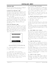
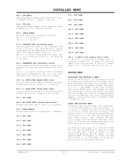
... STATUS OK Typical Installers Menu Detailed Descriptions of Installer Menu Items 0-I . When set by a wall switch. Settings range from either the remote or the TV front control panel, and the SLEEP TIMER is ON. This is desirable when the TV is automatically set to choose numbers that the TV will remain on the same channel. NOTE: BAND is plugged into a cable box or a power outlet controlled by AUTO PROGRAM. If some channels are given...
... STATUS OK Typical Installers Menu Detailed Descriptions of Installer Menu Items 0-I . When set by a wall switch. Settings range from either the remote or the TV front control panel, and the SLEEP TIMER is ON. This is desirable when the TV is automatically set to choose numbers that the TV will remain on the same channel. NOTE: BAND is plugged into a cable box or a power outlet controlled by AUTO PROGRAM. If some channels are given...
Service Manual
Page 5
... MENU on every TV. SLEEP TIMER When set to 1, the Sleep Timer feature is available to the user (but no programming restrictions can select channels with either from accessing screen menus with ADJ (adjust). ALARM Gives you the option of volume control. NOT USED 19-I . Set O, P LBL for the maximum V-Chip (Parental Control) block hours. V-CHIP Set to 1 to the user. Set to 0 to turn V-Chip feature off, not available to restore previous Caption...
... MENU on every TV. SLEEP TIMER When set to 1, the Sleep Timer feature is available to the user (but no programming restrictions can select channels with either from accessing screen menus with ADJ (adjust). ALARM Gives you the option of volume control. NOT USED 19-I . Set O, P LBL for the maximum V-Chip (Parental Control) block hours. V-CHIP Set to 1 to the user. Set to 0 to turn V-Chip feature off, not available to restore previous Caption...

Service Manual
Page 6
... identification change. 48-I . NOT USED 46-I . AUX source to front computer input. Channel-Time display will not appear. NOT USED 36-I . REAR Y/C EN. (Rear S-Video Enable) Set to 1 to disable V-Chip menu. VCHIP M. (Disable Parental Control Menu) Set to 1 to enable the rear S-Video input. AUTO COMPORT Set to 1 to automatically switch to Comport when equipment is connected to be reported as shown on Setup menu) channel search is connected to enable custom color settings for the Audio menu. 3828VD0171G 2-3 DIGITAL FCS...
... identification change. 48-I . NOT USED 46-I . AUX source to front computer input. Channel-Time display will not appear. NOT USED 36-I . REAR Y/C EN. (Rear S-Video Enable) Set to 1 to disable V-Chip menu. VCHIP M. (Disable Parental Control Menu) Set to 1 to enable the rear S-Video input. AUTO COMPORT Set to 1 to automatically switch to Comport when equipment is connected to be reported as shown on Setup menu) channel search is connected to enable custom color settings for the Audio menu. 3828VD0171G 2-3 DIGITAL FCS...

Service Manual
Page 7
...channel selection. 77-I . AUDIO. EN. BCK. Set to 0 to disable custom color settings for Channel- Time display, (foreground color = background color and custom color enabled) a large channel number is displayed when direct accessing a channel not in the favorite channel list. 74-I . Set to 0 to disable XDS display. VIDEO. SRC. FOR. Set to 0 to disable custom color for the Source menu. 67-I . Set to 0 to Color Chart. 0 = Black 3 = Yellow 6 = Cyan 1 = Red 4 = Blue 7 = White 2 = Green 5 = Violet 62-I . SRC. EN. VIDEO M. (Video Menu Foreground Color...
...channel selection. 77-I . AUDIO. EN. BCK. Set to 0 to disable custom color settings for Channel- Time display, (foreground color = background color and custom color enabled) a large channel number is displayed when direct accessing a channel not in the favorite channel list. 74-I . Set to 0 to disable XDS display. VIDEO. SRC. FOR. Set to 0 to disable custom color for the Source menu. 67-I . Set to 0 to Color Chart. 0 = Black 3 = Yellow 6 = Cyan 1 = Red 4 = Blue 7 = White 2 = Green 5 = Violet 62-I . SRC. EN. VIDEO M. (Video Menu Foreground Color...
Service Manual
Page 8
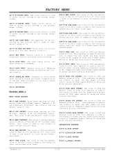
... ENTER. MUTE TIME (Audio Mute Time) Controls audio muting delay time when switching between AUX sources. V. NOT USED 99-I . At power On, previous aspect ratio will be used. FACTORY MENU ACCESSING THE FACTORY'S MENU Using the remote control or the keyboard on the following pages. Their numbers, descriptions, ranges, factory default settings, and a place for validation. command. (SN-HIGH) 81-I . NOT USED 104-I . To change the settings use the Left/Right ADJ keys. 3828VD0171G 2-5 DIGITAL FCS - Set to install Parental Control blocking restrictions...
... ENTER. MUTE TIME (Audio Mute Time) Controls audio muting delay time when switching between AUX sources. V. NOT USED 99-I . At power On, previous aspect ratio will be used. FACTORY MENU ACCESSING THE FACTORY'S MENU Using the remote control or the keyboard on the following pages. Their numbers, descriptions, ranges, factory default settings, and a place for validation. command. (SN-HIGH) 81-I . NOT USED 104-I . To change the settings use the Left/Right ADJ keys. 3828VD0171G 2-5 DIGITAL FCS - Set to install Parental Control blocking restrictions...

Service Manual
Page 9
...-pass gain). 014-F PRE AUX_INPUT: Defines the input gain value for the demodulated audio signal. Fixed value = 24. 016-F AVC: Automatic volume correction decay time. Fixed value = 4. Contrast gain control (Y system level adjustment). FACTORY MENU Change Factory's Menu Item "00 F Mode" to set the time. 4. Use the ADJUST keys. 004-F HORZ POS: Moves Captions and displays horizontally on the menus are inhibited while the Factory Mode is for enable or disable the AFT...
...-pass gain). 014-F PRE AUX_INPUT: Defines the input gain value for the demodulated audio signal. Fixed value = 24. 016-F AVC: Automatic volume correction decay time. Fixed value = 4. Contrast gain control (Y system level adjustment). FACTORY MENU Change Factory's Menu Item "00 F Mode" to set the time. 4. Use the ADJUST keys. 004-F HORZ POS: Moves Captions and displays horizontally on the menus are inhibited while the Factory Mode is for enable or disable the AFT...

Service Manual
Page 10
... picture level control. Range 0-15. Fixed value. 021-F BDRIVE B channel drive gain control. Default value is 1 (off , normal color temperature. 032-F CTILEV AUX: Chrominance transient improvement for Aux video input. 033-F CTIMODE AUX: Chrominance transient mode for Aux video input. 034-F COLAXIS: Color detection axis setting. 0= for NTSC. 035-F GAMMAL: Fine tuning for gamma. 036-F LTILEV AUX: Luminance signal edge enhancement setting for ABLIN (Pin 44) input...
... picture level control. Range 0-15. Fixed value. 021-F BDRIVE B channel drive gain control. Default value is 1 (off , normal color temperature. 032-F CTILEV AUX: Chrominance transient improvement for Aux video input. 033-F CTIMODE AUX: Chrominance transient mode for Aux video input. 034-F COLAXIS: Color detection axis setting. 0= for NTSC. 035-F GAMMAL: Fine tuning for gamma. 036-F LTILEV AUX: Luminance signal edge enhancement setting for ABLIN (Pin 44) input...

Service Manual
Page 11
.... Range: 0-15, Initial value: 07. 074-F V_POSITION: Vertical position adjustment. FACTORY MENU Default value is 0. 077-F V_S_CORRECTION: Vertical S correction. Range: 0-63, Initial value: 31. 075-F V_SCROLL: Vertical picture scroll control. Range: 0-3, Initial value: 0. 088-F UP_UCG: Horizontal pin gain adjustment for horizontal picture size. Range: 0-63, Initial value: 31. 072-F V_ASPECT: Aspect control ratio. Range: 0- 15, Initial value: 07. 055-F BLKOFF: Blanking ON...
.... Range: 0-15, Initial value: 07. 074-F V_POSITION: Vertical position adjustment. FACTORY MENU Default value is 0. 077-F V_S_CORRECTION: Vertical S correction. Range: 0-63, Initial value: 31. 075-F V_SCROLL: Vertical picture scroll control. Range: 0-3, Initial value: 0. 088-F UP_UCG: Horizontal pin gain adjustment for horizontal picture size. Range: 0-63, Initial value: 31. 072-F V_ASPECT: Aspect control ratio. Range: 0- 15, Initial value: 07. 055-F BLKOFF: Blanking ON...

Service Manual
Page 12
... master picture in 1. 100-F HWIDTH: Sets the SELH OUT output pulse width. 2=1.7us. 101-F HFREQ: Select the frequency of clamping pulse. Range: 0-7, Initial value: 0. 095-F APC-MODE 096-F SYNC-PHASE 097-F RST-SW NTSC: IC CXA2151 115-F HUEM: Tint control for NTSC signals. 116-F AGCMDM: AGC behavior can be chosen from four possible modes. 117-F AGCADJ1M: Automatic gain adjustment...
... master picture in 1. 100-F HWIDTH: Sets the SELH OUT output pulse width. 2=1.7us. 101-F HFREQ: Select the frequency of clamping pulse. Range: 0-7, Initial value: 0. 095-F APC-MODE 096-F SYNC-PHASE 097-F RST-SW NTSC: IC CXA2151 115-F HUEM: Tint control for NTSC signals. 116-F AGCMDM: AGC behavior can be chosen from four possible modes. 117-F AGCADJ1M: Automatic gain adjustment...
Service Manual
Page 15
... NTSC video format. FACTORY MENU 227-F R-CUTOFF NTSC: Red cutoff control is used to adjust cut-off . This register is used in one formula to reset the red, green and blue gain values of component inputs before G2 setup and white balance adjustment. 012-F SVGA CUT OFFSET: Max value of 254d and default value of 32d. 002-F YUV OFFSET: Black level setting for 32". This value is used in...
... NTSC video format. FACTORY MENU 227-F R-CUTOFF NTSC: Red cutoff control is used to adjust cut-off . This register is used in one formula to reset the red, green and blue gain values of component inputs before G2 setup and white balance adjustment. 012-F SVGA CUT OFFSET: Max value of 254d and default value of 32d. 002-F YUV OFFSET: Black level setting for 32". This value is used in...

Service Manual
Page 18
... CXA2150 108-F LTILEV_YPRPB: Luminance signal edge enhancement setting for RF input. Default value is 3. 113-F CTIMODE_RF: Chrominance transient mode for Component video input. Default value is 1 NTSC: VSP9405. 114-F LTILEV_RF: Luminance signal edge enhancement setting for RF input. Range: 0- 3, 0 = NORMAL, 1 = FF, 2 = HD, 3 = FIX-HD (setting which is 0 (Negative feedback polarity selected, No external DAC voltage outputs. FACTORY MENU 099-F R-CUTOFF Y PrPb: Red cutoff control is used to adjust cut-off voltage at the...
... CXA2150 108-F LTILEV_YPRPB: Luminance signal edge enhancement setting for RF input. Default value is 3. 113-F CTIMODE_RF: Chrominance transient mode for Component video input. Default value is 1 NTSC: VSP9405. 114-F LTILEV_RF: Luminance signal edge enhancement setting for RF input. Range: 0- 3, 0 = NORMAL, 1 = FF, 2 = HD, 3 = FIX-HD (setting which is 0 (Negative feedback polarity selected, No external DAC voltage outputs. FACTORY MENU 099-F R-CUTOFF Y PrPb: Red cutoff control is used to adjust cut-off voltage at the...
Service Manual
Page 23
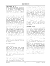
... are in to the audio processor. The power amplifier IC801 takes the Left and Right channels from external audio sources (Rear and Front jack packs). The A/V Switch chooses one scan card that can be plugged in use the Aux. The output signals of the Audio/Video input External sources: Video Aux., S-Video, Rear Computer, Front Computer/Video or from Scan Card (when this output stage is used with a resistor (RM5123) connected between bandwidth, overshoot, and...
... are in to the audio processor. The power amplifier IC801 takes the Left and Right channels from external audio sources (Rear and Front jack packs). The A/V Switch chooses one scan card that can be plugged in use the Aux. The output signals of the Audio/Video input External sources: Video Aux., S-Video, Rear Computer, Front Computer/Video or from Scan Card (when this output stage is used with a resistor (RM5123) connected between bandwidth, overshoot, and...
Service Manual
Page 24
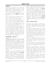
... to the internal reference black level during signal black level. Switched luminance and chrominance signals are the power supplies for the RGB output stages. Also, receives the H, V SYNC -SCAN (comes from the luminance composite sync. The output of the ICM2200 is a bipolar IC which integrates base band Y/ C signal processing, RGB processing, Horizontal sync signal processing that support 37.9Khz. Very small input currents will discharge...
... to the internal reference black level during signal black level. Switched luminance and chrominance signals are the power supplies for the RGB output stages. Also, receives the H, V SYNC -SCAN (comes from the luminance composite sync. The output of the ICM2200 is a bipolar IC which integrates base band Y/ C signal processing, RGB processing, Horizontal sync signal processing that support 37.9Khz. Very small input currents will discharge...
Service Manual
Page 25
... contrast setting, contrast modulation and beam current limiting. SERVICING In the output stage the nominal input signal will be amplified to achieve fast rise and fall times of the output signals with minimum crosstalk between Channels, each signal stage has its own supply voltage pin. The pin LIM (pin 24) is defined by output clamping (pin 11 HFB). Reference or pedestal black levels are adjusted...
... contrast setting, contrast modulation and beam current limiting. SERVICING In the output stage the nominal input signal will be amplified to achieve fast rise and fall times of the output signals with minimum crosstalk between Channels, each signal stage has its own supply voltage pin. The pin LIM (pin 24) is defined by output clamping (pin 11 HFB). Reference or pedestal black levels are adjusted...
Service Manual
Page 27
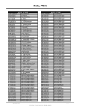
MODEL PARTS PART NUMBER 0DZ910009AJ 0FS5001B51D 0IAL241610B 0IAL242561B 0ICTMFA001A 0ICTMMI060A 0IFA753307A 0IKE358000A 0IKE704200B 0IKE780500P 0IKE780500Q 0IKE780800J 0ILI817000G 0ILNRJR017A ...Sound/Audio Processor IC,Unclassified IC,DC,DC Converter IC, Transceiver IC,Voltage Regulator IC, LDO Voltage Regulator IC, Micro Controller IC, Graphic Controller IC,DDR SDRAM IC, Pre Amplifier IC, Video Amplifier IC, Voltage Regulator IC, PWM Controller IC, Data Controller IC, Analog Switch IC, Motor Driver IC,Vertical Deflection Circuit IC, LDO Voltage Regulator IC, Power Amplifier IC, Analog Switch...
MODEL PARTS PART NUMBER 0DZ910009AJ 0FS5001B51D 0IAL241610B 0IAL242561B 0ICTMFA001A 0ICTMMI060A 0IFA753307A 0IKE358000A 0IKE704200B 0IKE780500P 0IKE780500Q 0IKE780800J 0ILI817000G 0ILNRJR017A ...Sound/Audio Processor IC,Unclassified IC,DC,DC Converter IC, Transceiver IC,Voltage Regulator IC, LDO Voltage Regulator IC, Micro Controller IC, Graphic Controller IC,DDR SDRAM IC, Pre Amplifier IC, Video Amplifier IC, Voltage Regulator IC, PWM Controller IC, Data Controller IC, Analog Switch IC, Motor Driver IC,Vertical Deflection Circuit IC, LDO Voltage Regulator IC, Power Amplifier IC, Analog Switch...
Service Manual
Page 28
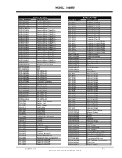
... Harness, Single Harness, Single Harness,Single Harness, Single Harness,Single Harness, Single Harness, Single Magnet, Stick Ferrite Magnet,Rubber Button Button Lead Set Harness, Single Varistor Coil, Choke Coil, Degaussing Coil, Linearity Inductor,Wire Wound,Chip Transformer, Switching Transformer, SMPS (Coil) Transformer,Switching FBT (Fly Back Transformer) Filter, Saw Filter, Ceramic 3828VD0171G 4-3 DIGITAL FCS-49 SERIES MODEL PARTS
... Harness, Single Harness, Single Harness,Single Harness, Single Harness,Single Harness, Single Harness, Single Magnet, Stick Ferrite Magnet,Rubber Button Button Lead Set Harness, Single Varistor Coil, Choke Coil, Degaussing Coil, Linearity Inductor,Wire Wound,Chip Transformer, Switching Transformer, SMPS (Coil) Transformer,Switching FBT (Fly Back Transformer) Filter, Saw Filter, Ceramic 3828VD0171G 4-3 DIGITAL FCS-49 SERIES MODEL PARTS
Service Manual
Page 31
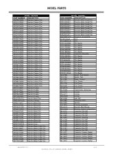
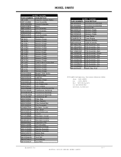
MODEL PARTS MODEL: H32H49S PART NUMBER DESCRIPTION 0RD2200F609 Resistor,Carbon Film 0RD2201F609 Resistor,Carbon Film 0RD2202F609 Resistor,Carbon Film 0RD2400H609 Resistor... Button 140-315A Switch, Tact 141-018E Relay, Contact 150-717J Coil, Choke 150-717K Coil,Choke 150-C02F Coil, Choke 150-W01A Coil,Choke 151-E06A Transformer, Switching 156-A01B Crystal 156-A01T Crystal 156-A02M Crystal 162-002B Led, DIP 163-048D... Capacitor,Ceramic,Radial 181-091Q Capacitor,Ceramic,Radial 181-091V Capacitor,Ceramic,Radial 3828VD0171G 4-6 DIGITAL FCS-49 SERIES MODEL PARTS
MODEL PARTS MODEL: H32H49S PART NUMBER DESCRIPTION 0RD2200F609 Resistor,Carbon Film 0RD2201F609 Resistor,Carbon Film 0RD2202F609 Resistor,Carbon Film 0RD2400H609 Resistor... Button 140-315A Switch, Tact 141-018E Relay, Contact 150-717J Coil, Choke 150-717K Coil,Choke 150-C02F Coil, Choke 150-W01A Coil,Choke 151-E06A Transformer, Switching 156-A01B Crystal 156-A01T Crystal 156-A02M Crystal 162-002B Led, DIP 163-048D... Capacitor,Ceramic,Radial 181-091Q Capacitor,Ceramic,Radial 181-091V Capacitor,Ceramic,Radial 3828VD0171G 4-6 DIGITAL FCS-49 SERIES MODEL PARTS
Service Manual
Page 32
... CPT Assembly 6400VA0025B Speaker,Fullrange 6401VC0N04E Speaker Assembly 6401VC0N05E Speaker Assembly 6600Q000070 Switch,Slide 6600R00004A Switch,Tact 6612VBH001B Jack,DIN 6612VEH001C Jack,Modular 6613V00004T Jack,RCA MODEL: H32H49S PART NUMBER DESCRIPTION 6613V00027A Connector,Unclassified 6613V00028A Connector,Unclassified 6620VBD002A Socket,CRT 6631V25014D Harness, Single 6631V25035H Harness, Single 6631V25A04A Harness, Single 6700AT0001A Tuner,Digital 6700NF0017A Tuner,Analog 6726VV0006J Receiver Module 6850VA0002A Cable,Assembly 68719SMJ78C PCB...
... CPT Assembly 6400VA0025B Speaker,Fullrange 6401VC0N04E Speaker Assembly 6401VC0N05E Speaker Assembly 6600Q000070 Switch,Slide 6600R00004A Switch,Tact 6612VBH001B Jack,DIN 6612VEH001C Jack,Modular 6613V00004T Jack,RCA MODEL: H32H49S PART NUMBER DESCRIPTION 6613V00027A Connector,Unclassified 6613V00028A Connector,Unclassified 6620VBD002A Socket,CRT 6631V25014D Harness, Single 6631V25035H Harness, Single 6631V25A04A Harness, Single 6700AT0001A Tuner,Digital 6700NF0017A Tuner,Analog 6726VV0006J Receiver Module 6850VA0002A Cable,Assembly 68719SMJ78C PCB...


