Owners Manual
Page 2
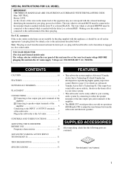
... Please record the serial number of this system in a safe place for long periods of time. 14 Refer all instructions. 5 Do not use this Owner's Manual in the space below. Install in accordance with the manufacturer's instructions. 8 Do not install near water. 6 Clean only with dry cloth. 7 Do not block any heat sources such as power-supply cord or plug is damaged, liquid...
... Please record the serial number of this system in a safe place for long periods of time. 14 Refer all instructions. 5 Do not use this Owner's Manual in the space below. Install in accordance with the manufacturer's instructions. 8 Do not install near water. 6 Clean only with dry cloth. 7 Do not block any heat sources such as power-supply cord or plug is damaged, liquid...
Owners Manual
Page 3
This equipment generates/uses radio frequencies and, if not installed and used . Compliance with this product in FCC Regulations, Part 15 for US customers) 1 IMPORTANT NOTICE: DO NOT MODIFY THIS UNIT! Since hearing damage from excessive volume levels. ii Cable/s supplied with FCC regulations does not guarantee that interference will not result in harmful interference with the requirements listed in the USA...
This equipment generates/uses radio frequencies and, if not installed and used . Compliance with this product in FCC Regulations, Part 15 for US customers) 1 IMPORTANT NOTICE: DO NOT MODIFY THIS UNIT! Since hearing damage from excessive volume levels. ii Cable/s supplied with FCC regulations does not guarantee that interference will not result in harmful interference with the requirements listed in the USA...
Owners Manual
Page 4
.... When moving the unit, first disconnect the power plug and the wires connected to other surfaces. • Do not cover the rear panel of a movie soundtrack's low frequency, bass-heavy sounds or similarly loud popular music passages can be reached easily. • Secure placement or installation is still a chance that placing it too close to a TV set . • Do not attempt to the...
.... When moving the unit, first disconnect the power plug and the wires connected to other surfaces. • Do not cover the rear panel of a movie soundtrack's low frequency, bass-heavy sounds or similarly loud popular music passages can be reached easily. • Secure placement or installation is still a chance that placing it too close to a TV set . • Do not attempt to the...
Owners Manual
Page 5
...-home effect to your stereo system. • This subwoofer can be connected to the instructions described below. For U.K. VOLTAGE SELECTOR (For Asia and General models only) The voltage selector switch on Advanced Yamaha Active Servo Technology II.) This super-bass sound adds a more realistic, theater-in the mains lead of this unit must be easily added to either the speaker terminals or the line output...
...-home effect to your stereo system. • This subwoofer can be connected to the instructions described below. For U.K. VOLTAGE SELECTOR (For Asia and General models only) The voltage selector switch on Advanced Yamaha Active Servo Technology II.) This super-bass sound adds a more realistic, theater-in the mains lead of this unit must be easily added to either the speaker terminals or the line output...

Owners Manual
Page 6
... speaker. (See fig. B .) The placement shown in fig. A or B . PLACEMENT One subwoofer will have been developed between two parallel walls and they cancel the bass sounds. In such a case, face the subwoofer obliquely to break up the parallel surfaces by vibrations etc. ( : subwoofer, : front speaker) 2 If using two subwoofers, it is recommended to place them on your audio A system, however, the use of two subwoofers...
... speaker. (See fig. B .) The placement shown in fig. A or B . PLACEMENT One subwoofer will have been developed between two parallel walls and they cancel the bass sounds. In such a case, face the subwoofer obliquely to break up the parallel surfaces by vibrations etc. ( : subwoofer, : front speaker) 2 If using two subwoofers, it is recommended to place them on your audio A system, however, the use of two subwoofers...
Owners Manual
Page 7
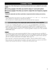
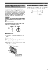
... of the amplifier, make sure that the amplifier has at least two sets of PRE OUT terminals. Also, refer to the owner's manual of your audio system. ■Choose 1 (pages 3-4) when you want to output the low frequency signals Caution Unplug the subwoofer and other audio/video components. 1 Connecting to line output (pin jack) terminals of the amplifier • To connect with a YAMAHA DSP amplifier (or AV receiver), connect the SUBWOOFER (or...
... of the amplifier, make sure that the amplifier has at least two sets of PRE OUT terminals. Also, refer to the owner's manual of your audio system. ■Choose 1 (pages 3-4) when you want to output the low frequency signals Caution Unplug the subwoofer and other audio/video components. 1 Connecting to line output (pin jack) terminals of the amplifier • To connect with a YAMAHA DSP amplifier (or AV receiver), connect the SUBWOOFER (or...

Owners Manual
Page 8
CONNECTIONS ■ Using one subwoofer Subwoofer OUTPUT TO SPEAKERS INPUT 1 FROM AMPLIFIER INPUT 2 HIGH CUT /MONO VOLUME HIGH LOW POWER ON OFF To AC outlet OUTPUT TO SPEAKERS INPUT 1 FROM AMPLIFIER INPUT 2 HIGH CUT /MONO HIGH LOW Amplifier Mono pin cable (not included) Audio pin cable (not included) ■ Using two subwoofers OUTPUT TO SPEAKERS INPUT 1 FROM AMPLIFIER INPUT 2 HIGH CUT /MONO HIGH LOW Mono pin cable (not included) OUTPUT TO SPEAKERS INPUT 1 FROM AMPLIFIER INPUT 2 HIGH CUT /MONO HIGH LOW OUTPUT TO SPEAKERS INPUT 1 FROM AMPLIFIER INPUT 2 HIGH...
CONNECTIONS ■ Using one subwoofer Subwoofer OUTPUT TO SPEAKERS INPUT 1 FROM AMPLIFIER INPUT 2 HIGH CUT /MONO VOLUME HIGH LOW POWER ON OFF To AC outlet OUTPUT TO SPEAKERS INPUT 1 FROM AMPLIFIER INPUT 2 HIGH CUT /MONO HIGH LOW Amplifier Mono pin cable (not included) Audio pin cable (not included) ■ Using two subwoofers OUTPUT TO SPEAKERS INPUT 1 FROM AMPLIFIER INPUT 2 HIGH CUT /MONO HIGH LOW Mono pin cable (not included) OUTPUT TO SPEAKERS INPUT 1 FROM AMPLIFIER INPUT 2 HIGH CUT /MONO HIGH LOW OUTPUT TO SPEAKERS INPUT 1 FROM AMPLIFIER INPUT 2 HIGH...
Owners Manual
Page 9
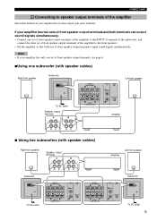
...sets of front speaker output terminals and both terminals can output sound signals simultaneously. • Connect one subwoofer (with speaker cables) Right front speaker Subwoofer OUTPUT TO SPEAKERS INPUT 1 FROM AMPLIFIER INPUT 2 HIGH CUT /MONO VOLUME HIGH LOW POWER ON OFF To AC outlet Speaker output terminals OUTPUT TO SPEAKERS INPUT 1 FROM AMPLIFIER INPUT 2 HIGH CUT /MONO HIGH LOW Left front speaker Amplifier ■ Using two subwoofers (with speaker cables) Right front speaker Speaker output terminals Amplifier Left front speaker Subwoofer OUTPUT TO SPEAKERS INPUT...
...sets of front speaker output terminals and both terminals can output sound signals simultaneously. • Connect one subwoofer (with speaker cables) Right front speaker Subwoofer OUTPUT TO SPEAKERS INPUT 1 FROM AMPLIFIER INPUT 2 HIGH CUT /MONO VOLUME HIGH LOW POWER ON OFF To AC outlet Speaker output terminals OUTPUT TO SPEAKERS INPUT 1 FROM AMPLIFIER INPUT 2 HIGH CUT /MONO HIGH LOW Left front speaker Amplifier ■ Using two subwoofers (with speaker cables) Right front speaker Speaker output terminals Amplifier Left front speaker Subwoofer OUTPUT TO SPEAKERS INPUT...
Owners Manual
Page 10
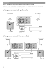
...to the front speakers. ■ Using one set of front speaker output terminals. CONNECTIONS If your amplifier has only one subwoofer (with speaker cables) Right front speaker Left front speaker Subwoofer OUTPUT TO SPEAKERS INPUT 1 FROM AMPLIFIER INPUT 2 HIGH CUT /MONO VOLUME HIGH LOW POWER ON OFF OUTPUT TO SPEAKERS INPUT 1 FROM AMPLIFIER INPUT 2 HIGH CUT /MONO HIGH LOW Amplifier To AC outlet Speaker output terminals ■ Using two subwoofers (with speaker cables) Right front speaker Left front speaker Subwoofer OUTPUT TO SPEAKERS INPUT 1 FROM AMPLIFIER INPUT 2 HIGH...
...to the front speakers. ■ Using one set of front speaker output terminals. CONNECTIONS If your amplifier has only one subwoofer (with speaker cables) Right front speaker Left front speaker Subwoofer OUTPUT TO SPEAKERS INPUT 1 FROM AMPLIFIER INPUT 2 HIGH CUT /MONO VOLUME HIGH LOW POWER ON OFF OUTPUT TO SPEAKERS INPUT 1 FROM AMPLIFIER INPUT 2 HIGH CUT /MONO HIGH LOW Amplifier To AC outlet Speaker output terminals ■ Using two subwoofers (with speaker cables) Right front speaker Left front speaker Subwoofer OUTPUT TO SPEAKERS INPUT 1 FROM AMPLIFIER INPUT 2 HIGH...
Owners Manual
Page 11
... connection, keep the speaker cables as short as shown in the subwoofer and other , because this could damage the subwoofer or the amplifier, or both of the connection by twisting the coating off. Make sure that the + and - Caution Do not let the bare speaker wires touch each speaker cable by pulling lightly on the cable's wire end. 4 Test the firmness of them . ■Before connecting Remove...
... connection, keep the speaker cables as short as shown in the subwoofer and other , because this could damage the subwoofer or the amplifier, or both of the connection by twisting the coating off. Make sure that the + and - Caution Do not let the bare speaker wires touch each speaker cable by pulling lightly on the cable's wire end. 4 Test the firmness of them . ■Before connecting Remove...
Owners Manual
Page 12
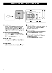
.... CONTROLS AND THEIR FUNCTIONS Subwoofer rear panel 1 OUTPUT TO SPEAKERS INPUT 1 FROM AMPLIFIER INPUT 2 HIGH CUT /MONO VOLUME HIGH LOW POWER ON OFF 2 OUTPUT TO SPEAKERS INPUT 1 FROM AMPLIFIER 7 INPUT 2 HIGH CUT 34 /MONO HIGH LOW VOLUME 65 1 POWER switch Press this switch again to set to HIGH if necessary. (Refer to page 9) 6 INPUT 2 terminals Used to input line level signals from the amplifier. (Refer to "CONNECTIONS" for details.) 7 INPUT 1 (FROM AMPLIFIER) terminals Used to connect the subwoofer with the speaker terminals of the subwoofer. 2 OUTPUT...
.... CONTROLS AND THEIR FUNCTIONS Subwoofer rear panel 1 OUTPUT TO SPEAKERS INPUT 1 FROM AMPLIFIER INPUT 2 HIGH CUT /MONO VOLUME HIGH LOW POWER ON OFF 2 OUTPUT TO SPEAKERS INPUT 1 FROM AMPLIFIER 7 INPUT 2 HIGH CUT 34 /MONO HIGH LOW VOLUME 65 1 POWER switch Press this switch again to set to HIGH if necessary. (Refer to page 9) 6 INPUT 2 terminals Used to input line level signals from the amplifier. (Refer to "CONNECTIONS" for details.) 7 INPUT 1 (FROM AMPLIFIER) terminals Used to connect the subwoofer with the speaker terminals of the subwoofer. 2 OUTPUT...
Owners Manual
Page 13
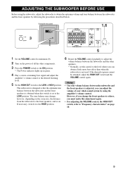
... CUT switch, refer to "Frequency characteristics" on the power of your whole sound system by following the procedures described below. 3 Subwoofer rear panel OUTPUT TO SPEAKERS INPUT 1 FROM AMPLIFIER INPUT 2 HIGH CUT /MONO VOLUME HIGH LOW POWER ON OFF OUTPUT TO SPEAKERS INPUT 1 FROM AMPLIFIER 1,6 INPUT 2 HIGH CUT /MONO HIGH LOW VOLUME 5 1 Set the VOLUME control to the LOW position. The tone balance may change the front speakers to others, you can obtain a little more bass...
... CUT switch, refer to "Frequency characteristics" on the power of your whole sound system by following the procedures described below. 3 Subwoofer rear panel OUTPUT TO SPEAKERS INPUT 1 FROM AMPLIFIER INPUT 2 HIGH CUT /MONO VOLUME HIGH LOW POWER ON OFF OUTPUT TO SPEAKERS INPUT 1 FROM AMPLIFIER 1,6 INPUT 2 HIGH CUT /MONO HIGH LOW VOLUME 5 1 Set the VOLUME control to the LOW position. The tone balance may change the front speakers to others, you can obtain a little more bass...
Owners Manual
Page 14
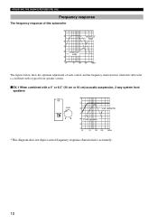
... each control and the frequency characteristics when this subwoofer is combined with a typical front speaker system. ■EX.1 When combined with a 4" or 6.5" (10 cm or 16 cm) acoustic suspension, 2 way system front speakers HIGH CUT VOLUME HIGH LOW dB 90 80 YST-SW216 70 60 Front speaker 50 40 20 50 100 200 500Hz *This diagram does not depict actual frequency response...
... each control and the frequency characteristics when this subwoofer is combined with a typical front speaker system. ■EX.1 When combined with a 4" or 6.5" (10 cm or 16 cm) acoustic suspension, 2 way system front speakers HIGH CUT VOLUME HIGH LOW dB 90 80 YST-SW216 70 60 Front speaker 50 40 20 50 100 200 500Hz *This diagram does not depict actual frequency response...
Owners Manual
Page 15
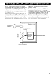
... driving the amplifier and speaker. This technique uses a direct connection between the speaker cabinet volume and port, it creates more stable performance and clear bass reproduction without any murkiness. High-amplitude bass sound Cabinet Port Air woofer (Helmholtz resonator) Advanced impedance Converter Active Servo Processing Amplifier Signals Signals of the amplifier and resonance generated between the amplifier and speaker, allowing accurate signal transmission and precise speaker control. Yamaha developed a new circuit...
... driving the amplifier and speaker. This technique uses a direct connection between the speaker cabinet volume and port, it creates more stable performance and clear bass reproduction without any murkiness. High-amplitude bass sound Cabinet Port Air woofer (Helmholtz resonator) Advanced impedance Converter Active Servo Processing Amplifier Signals Signals of the amplifier and resonance generated between the amplifier and speaker, allowing accurate signal transmission and precise speaker control. Yamaha developed a new circuit...
Owners Manual
Page 16
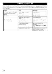
Sound level is played. Speaker cables are not connected correctly. Speaker cables are not connected securely. A source sound with bass frequencies. Problem Power is not supplied even though the POWER switch is set to the ON position. The volume is set to minimum. It is not listed below or if the instructions given below when this unit does not function properly. Raise the volume up the parallel surface by standing waves. Set the HIGH CUT switch to...
Sound level is played. Speaker cables are not connected correctly. Speaker cables are not connected securely. A source sound with bass frequencies. Problem Power is not supplied even though the POWER switch is set to the ON position. The volume is set to minimum. It is not listed below or if the instructions given below when this unit does not function properly. Raise the volume up the parallel surface by standing waves. Set the HIGH CUT switch to...
Owners Manual
Page 17
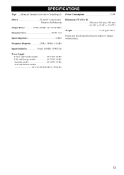
.../60 Hz 13 SPECIFICATIONS Type .....Advanced Yamaha Active Servo Technology II Power Consumption 45 W Driver 25 cm (10") cone woofer Magnetic shielding type Output Power 50 W (100 Hz, 5 Ω 10 %T.H.D) Dynamic Power 100 W, 5 Ω Input Impedance 12 KΩ Dimensions (W x H x D 340 mm x 340 mm x 385 mm (13-3/8" x 13-3/8" x 15-5/32") Weight 11.2 kg (24.7 lbs.) Please note that all specifications are subject to change without notice. Frequency Response 25 Hz...
.../60 Hz 13 SPECIFICATIONS Type .....Advanced Yamaha Active Servo Technology II Power Consumption 45 W Driver 25 cm (10") cone woofer Magnetic shielding type Output Power 50 W (100 Hz, 5 Ω 10 %T.H.D) Dynamic Power 100 W, 5 Ω Input Impedance 12 KΩ Dimensions (W x H x D 340 mm x 340 mm x 385 mm (13-3/8" x 13-3/8" x 15-5/32") Weight 11.2 kg (24.7 lbs.) Please note that all specifications are subject to change without notice. Frequency Response 25 Hz...

Owners Manual
Page 20
...., BUENA PARK, CALIF. 90620, U.S.A. SIEMENSSTR. 22-34, 25462 RELLINGEN BEI HAMBURG, GERMANY YAMAHA ELECTRONIQUE FRANCE S.A. J A WETTERGRENS GATA 1, BOX 30053, 400 43 VÄSTRA FRÖLUNDA, SWEDEN YAMAHA MUSIC AUSTRALIA PTY, LTD. 17-33 MARKET ST., SOUTH MELBOURNE, 3205 VIC., AUSTRALIA All rights reserved. YAMAHA CANADA MUSIC LTD. 135 MILNER AVE., SCARBOROUGH, ONTARIO M1S 3R1, CANADA...
...., BUENA PARK, CALIF. 90620, U.S.A. SIEMENSSTR. 22-34, 25462 RELLINGEN BEI HAMBURG, GERMANY YAMAHA ELECTRONIQUE FRANCE S.A. J A WETTERGRENS GATA 1, BOX 30053, 400 43 VÄSTRA FRÖLUNDA, SWEDEN YAMAHA MUSIC AUSTRALIA PTY, LTD. 17-33 MARKET ST., SOUTH MELBOURNE, 3205 VIC., AUSTRALIA All rights reserved. YAMAHA CANADA MUSIC LTD. 135 MILNER AVE., SCARBOROUGH, ONTARIO M1S 3R1, CANADA...


