Owner's Manual
Page 4
... to generate a howling sound. in a safe place for future reference. • Install this YAMAHA subwoofer system. If the object falls or drops by the air pressure, it may be damaged if ... humidification. Extremely loud playing of this unit uses a high voltage. If something drops into the YST port located on this unit. If glass etc. Using this unit with the rear panel facing ...down on a TV. It might fall. Furthermore, do not expose this speaker system. • Vibration generated by vibrations and water spills, it in order not to the ...
... to generate a howling sound. in a safe place for future reference. • Install this YAMAHA subwoofer system. If the object falls or drops by the air pressure, it may be damaged if ... humidification. Extremely loud playing of this unit uses a high voltage. If something drops into the YST port located on this unit. If glass etc. Using this unit with the rear panel facing ...down on a TV. It might fall. Furthermore, do not expose this speaker system. • Vibration generated by vibrations and water spills, it in order not to the ...
Owner's Manual
Page 5
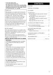
...THEIR FUNCTIONS 9 AUTO STANDBY FUNCTION 11 Activate the AUTO STANDBY function 11 For U.K. ADJUSTING THE SUBWOOFER BEFORE USE 12 Frequency characteristics 13 ADVANCED YAMAHA ACTIVE SERVO TECHNOLOGY II 14 TROUBLESHOOTING 15 SPECIFICATIONS Backcover For Canadian Customers To prevent electric shock, match...CONNECTIONS 4 1 Connecting to line output (pin jack) terminals of the amplifier 4 2 Connecting to speaker output terminals of the amplifier 6 Connecting to the INPUT1/ OUTPUT terminals of the subwoofer 8 Plug in the home are 110-120/220-240 V AC, 50/60 Hz. SPECIAL INSTRUCTIONS...
...THEIR FUNCTIONS 9 AUTO STANDBY FUNCTION 11 Activate the AUTO STANDBY function 11 For U.K. ADJUSTING THE SUBWOOFER BEFORE USE 12 Frequency characteristics 13 ADVANCED YAMAHA ACTIVE SERVO TECHNOLOGY II 14 TROUBLESHOOTING 15 SPECIFICATIONS Backcover For Canadian Customers To prevent electric shock, match...CONNECTIONS 4 1 Connecting to line output (pin jack) terminals of the amplifier 4 2 Connecting to speaker output terminals of the amplifier 6 Connecting to the INPUT1/ OUTPUT terminals of the subwoofer 8 Plug in the home are 110-120/220-240 V AC, 50/60 Hz. SPECIAL INSTRUCTIONS...
Owner's Manual
Page 6
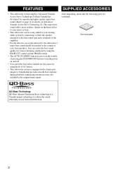
... the sound efficiently in four horizontal direction. 2 FEATURES • This subwoofer system employs Advanced Yamaha Active Servo Technology II which Yamaha has developed for reproducing higher quality super-bass sound. (Refer to page 14 for the source by connecting to either the speaker terminals or the line output (pin jack) terminals of the amplifier...
... the sound efficiently in four horizontal direction. 2 FEATURES • This subwoofer system employs Advanced Yamaha Active Servo Technology II which Yamaha has developed for reproducing higher quality super-bass sound. (Refer to page 14 for the source by connecting to either the speaker terminals or the line output (pin jack) terminals of the amplifier...
Owner's Manual
Page 7
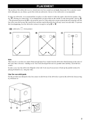
... low bass sounds are not highly directional. B .) The placement shown in fig. A .) If using one subwoofer, we recommend that you can obtain a good effect with one subwoofer, the use of the subwoofer to the wall. A or B . ( : subwoofer, : front speaker) A B C Note There may be a case that you place it and the sound reflected by the wall...
... low bass sounds are not highly directional. B .) The placement shown in fig. A .) If using one subwoofer, we recommend that you can obtain a good effect with one subwoofer, the use of the subwoofer to the wall. A or B . ( : subwoofer, : front speaker) A B C Note There may be a case that you place it and the sound reflected by the wall...
Owner's Manual
Page 8
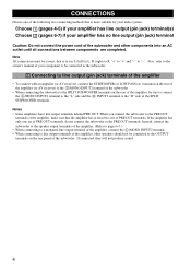
...to the owner's manual of your amplifier has no line output (pin jack) terminal Caution: Do not connect the power cord of the subwoofer and other speakers should not be connected to the OUTPUT terminals on the rear of the amplifier, be correct, that is more suitable for your audio ... has only one of the following two connecting methods that the amplifier has at least two sets of PRE OUT terminals. Instead, connect the subwoofer to the speaker output terminals of the amplifier. (Refer to pages 6-7.) • When connecting to a monaural line output terminal of the amplifier, connect the L /...
...to the owner's manual of your amplifier has no line output (pin jack) terminal Caution: Do not connect the power cord of the subwoofer and other speakers should not be connected to the OUTPUT terminals on the rear of the amplifier, be correct, that is more suitable for your audio ... has only one of the following two connecting methods that the amplifier has at least two sets of PRE OUT terminals. Instead, connect the subwoofer to the speaker output terminals of the amplifier. (Refer to pages 6-7.) • When connecting to a monaural line output terminal of the amplifier, connect the L /...

Owner's Manual
Page 9
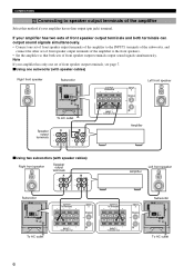
... 1 FROM AMPLIFIER CONNECTIONS Mono pin cable (not included) Audio pin cable (not included) ■ Using two subwoofers OUTPUT TO SPEAKERS INPUT 2 L /MONO Mono pin cable(not included) OUTPUT TO SPEAKERS INPUT 2 L /MONO Subwoofer INPUT 1 FROM AMPLIFIER R Subwoofer OUTPUT TO SPEAKERS INPUT 1 FROM AMPLIFIER INPUT PHASE 2 L /MONO NORM REV R AUTO STANDBY HIGH LOW OFF VOLTAGE SELECTOR 220V...
... 1 FROM AMPLIFIER CONNECTIONS Mono pin cable (not included) Audio pin cable (not included) ■ Using two subwoofers OUTPUT TO SPEAKERS INPUT 2 L /MONO Mono pin cable(not included) OUTPUT TO SPEAKERS INPUT 2 L /MONO Subwoofer INPUT 1 FROM AMPLIFIER R Subwoofer OUTPUT TO SPEAKERS INPUT 1 FROM AMPLIFIER INPUT PHASE 2 L /MONO NORM REV R AUTO STANDBY HIGH LOW OFF VOLTAGE SELECTOR 220V...
Owner's Manual
Page 10
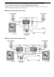
...POWER ON OFF To AC outlet Speaker output terminals OUTPUT TO SPEAKERS INPUT 2 L /MONO Left front speaker INPUT 1 FROM AMPLIFIER R Amplifier ■ Using two subwoofers (with speaker cables) Right front speaker Speaker output terminals Amplifier Left front speaker Subwoofer OUTPUT TO SPEAKERS INPUT 1 FROM AMPLIFIER INPUT PHASE...220V-240V 110V-120V POWER ON OFF To AC outlet OUTPUT TO SPEAKERS INPUT 2 L /MONO R INPUT 1 FROM AMPLIFIER OUTPUT TO SPEAKERS INPUT 1 FROM AMPLIFIER INPUT 2 L /MONO R Subwoofer OUTPUT TO SPEAKERS INPUT 1 FROM AMPLIFIER INPUT PHASE 2 L /MONO NORM REV...
...POWER ON OFF To AC outlet Speaker output terminals OUTPUT TO SPEAKERS INPUT 2 L /MONO Left front speaker INPUT 1 FROM AMPLIFIER R Amplifier ■ Using two subwoofers (with speaker cables) Right front speaker Speaker output terminals Amplifier Left front speaker Subwoofer OUTPUT TO SPEAKERS INPUT 1 FROM AMPLIFIER INPUT PHASE...220V-240V 110V-120V POWER ON OFF To AC outlet OUTPUT TO SPEAKERS INPUT 2 L /MONO R INPUT 1 FROM AMPLIFIER OUTPUT TO SPEAKERS INPUT 1 FROM AMPLIFIER INPUT 2 L /MONO R Subwoofer OUTPUT TO SPEAKERS INPUT 1 FROM AMPLIFIER INPUT PHASE 2 L /MONO NORM REV...
Owner's Manual
Page 11
... HIGH LOW OFF VOLTAGE SELECTOR 220V-240V 110V-120V POWER ON OFF OUTPUT TO SPEAKERS INPUT 2 L /MONO R INPUT 1 FROM AMPLIFIER Amplifier To AC outlet Speaker output terminals ■ Using two subwoofers (with speaker cables) Right front speaker Left front speaker Subwoofer OUTPUT TO SPEAKERS INPUT 1 FROM AMPLIFIER INPUT PHASE 2 L /MONO NORM REV R AUTO STANDBY HIGH LOW OFF VOLTAGE...
... HIGH LOW OFF VOLTAGE SELECTOR 220V-240V 110V-120V POWER ON OFF OUTPUT TO SPEAKERS INPUT 2 L /MONO R INPUT 1 FROM AMPLIFIER Amplifier To AC outlet Speaker output terminals ■ Using two subwoofers (with speaker cables) Right front speaker Left front speaker Subwoofer OUTPUT TO SPEAKERS INPUT 1 FROM AMPLIFIER INPUT PHASE 2 L /MONO NORM REV R AUTO STANDBY HIGH LOW OFF VOLTAGE...
Owner's Manual
Page 12
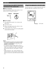
... connect 1 Press and hold the terminal's tab, as shown in the figure below. 2 Insert the bare wires. 3 Release your finger from the subwoofer or the speakers, or both of them . • Make sure that the + and - If these cables are faulty, no sound will be heard from the tab...will be unnatural and lack bass. 8 Good 10mm (3/8") No Good Plug in the subwoofer and other , because this could damage the subwoofer or the amplifier, or both of the speaker terminals are completed, plug in the subwoofer to the AC outlet After all connections are observed and set correctly. Notes •...
... connect 1 Press and hold the terminal's tab, as shown in the figure below. 2 Insert the bare wires. 3 Release your finger from the subwoofer or the speakers, or both of them . • Make sure that the + and - If these cables are faulty, no sound will be heard from the tab...will be unnatural and lack bass. 8 Good 10mm (3/8") No Good Plug in the subwoofer and other , because this could damage the subwoofer or the amplifier, or both of the speaker terminals are completed, plug in the subwoofer to the AC outlet After all connections are observed and set correctly. Notes •...
Owner's Manual
Page 13
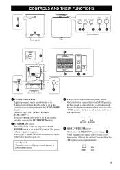
...-120V C OUTPUT TO SPEAKERS INPUT 1 FROM AMPLIFIER INPUT PHASE 2 L /MONO NORM REV R AUTO STANDBY HIGH LOW OFF VOLTAGE SELECTOR 220V-240V 110V-120V POWER ON OFF Rear panel (General model) INPUT 1 FROM AMPLIFIER 0 POWER ON OFF 7 NORM REV R AB 1 POWER INDICATOR Lights up in green while the subwoofer is on the power... when the POWER switch is set in the ON position. (The power indicator lights up in red while the subwoofer is set in the standby mode by the operation of AUTO STANDBY function. (Refer to page 11 of power in this mode. 3 B.A.S.S. (Bass Action Selector ...
...-120V C OUTPUT TO SPEAKERS INPUT 1 FROM AMPLIFIER INPUT PHASE 2 L /MONO NORM REV R AUTO STANDBY HIGH LOW OFF VOLTAGE SELECTOR 220V-240V 110V-120V POWER ON OFF Rear panel (General model) INPUT 1 FROM AMPLIFIER 0 POWER ON OFF 7 NORM REV R AB 1 POWER INDICATOR Lights up in green while the subwoofer is on the power... when the POWER switch is set in the ON position. (The power indicator lights up in red while the subwoofer is set in the standby mode by the operation of AUTO STANDBY function. (Refer to page 11 of power in this mode. 3 B.A.S.S. (Bass Action Selector ...
Owner's Manual
Page 14
... cut off point. Set this switch to the ON position to unplug the subwoofer before setting the VOLTAGE SELECTOR switch correctly. WARNING Be sure to use the subwoofer. However, according to the front speakers. Select the better position by pressing the STANDBY/ON button. CONTROLS AND THEIR... HIGH CUT control Adjusts the high frequency cut off the subwoofer's power supply from the AC line. 8 AUTO STANDBY (HIGH/LOW/OFF) switch This switch is obtained by pressing the STANDBY/ON button. 9 OUTPUT (TO SPEAKERS) terminals Can be used for connecting to your area. Turn...
... cut off point. Set this switch to the ON position to unplug the subwoofer before setting the VOLTAGE SELECTOR switch correctly. WARNING Be sure to use the subwoofer. However, according to the front speakers. Select the better position by pressing the STANDBY/ON button. CONTROLS AND THEIR... HIGH CUT control Adjusts the high frequency cut off the subwoofer's power supply from the AC line. 8 AUTO STANDBY (HIGH/LOW/OFF) switch This switch is obtained by pressing the STANDBY/ON button. 9 OUTPUT (TO SPEAKERS) terminals Can be used for connecting to your area. Turn...
Owner's Manual
Page 16
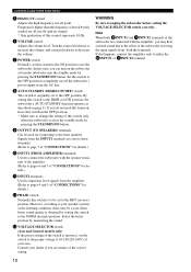
... control to the level where you can adjust the volume of your whole sound system by using the subwoofer, adjust the subwoofer to obtain the optimum volume and tone balance between the subwoofer and the front speakers by following the procedures described below. 7 3 3 8 5 1,6 NORM REV POWER ON OFF 1 ..., adjust the HIGH CUT control and the VOLUME control again. 7 Set the PHASE switch to adjust the volume balance between the subwoofer and the front speakers. MUSIC: When an ordinary music source is played, the lowfrequency effects are cut off to make this adjustment again. • ...
... control to the level where you can adjust the volume of your whole sound system by using the subwoofer, adjust the subwoofer to obtain the optimum volume and tone balance between the subwoofer and the front speakers by following the procedures described below. 7 3 3 8 5 1,6 NORM REV POWER ON OFF 1 ..., adjust the HIGH CUT control and the VOLUME control again. 7 Set the PHASE switch to adjust the volume balance between the subwoofer and the front speakers. MUSIC: When an ordinary music source is played, the lowfrequency effects are cut off to make this adjustment again. • ...
Owner's Manual
Page 17
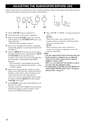
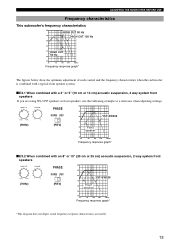
...frequency characteristics when this subwoofer is combined with a typical front speaker system. ■ EX.1 When combined with an 8" or 10" (20 cm or 25 cm) acoustic suspension, 2 way system front speakers (70Hz) PHASE NORM REV (REV) dB 90 80 YST-SW325 70 60 Front speaker 50 40 20 ...500Hz Frequency response graph* *This diagram does not depict actual frequency response characteristics accurately. 13 dB PHASE 90 NORM REV 80 YST-SW325 (90Hz) (REV) 70 60 Front speaker 50 40 20 50 100 200 500Hz Frequency response graph* ■ EX.2 When combined with a 4" or 5" (10...
...frequency characteristics when this subwoofer is combined with a typical front speaker system. ■ EX.1 When combined with an 8" or 10" (20 cm or 25 cm) acoustic suspension, 2 way system front speakers (70Hz) PHASE NORM REV (REV) dB 90 80 YST-SW325 70 60 Front speaker 50 40 20 ...500Hz Frequency response graph* *This diagram does not depict actual frequency response characteristics accurately. 13 dB PHASE 90 NORM REV 80 YST-SW325 (90Hz) (REV) 70 60 Front speaker 50 40 20 50 100 200 500Hz Frequency response graph* ■ EX.2 When combined with a 4" or 5" (10...
Owner's Manual
Page 19
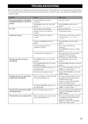
...the "HIGH" or "LOW" position. Set the STANDBY/ON button to Do Connect it securely. Move the subwoofer farther away from such appliances and/or reposition the connected speaker cables. Set the AUTO STANDBY switch to the "OFF" position. 15 Otherwise, set to the "HIGH" ...not function properly. The subwoofer turns on automatically. The subwoofer does not turn into the standby mode unexpectedly. Set the POWER switch to the chart below do not help, disconnect the power cord and contact your authorized YAMAHA dealer or service center. Speaker cables are not connected securely...
...the "HIGH" or "LOW" position. Set the STANDBY/ON button to Do Connect it securely. Move the subwoofer farther away from such appliances and/or reposition the connected speaker cables. Set the AUTO STANDBY switch to the "OFF" position. 15 Otherwise, set to the "HIGH" ...not function properly. The subwoofer turns on automatically. The subwoofer does not turn into the standby mode unexpectedly. Set the POWER switch to the chart below do not help, disconnect the power cord and contact your authorized YAMAHA dealer or service center. Speaker cables are not connected securely...


