Owner's Manual
Page 2
...instructions. 5 Do not use this apparatus near any heat sources such as power-supply cord or plug is damaged, liquid has been spilled or objects have fallen into your safety. Install in the space below. A polarized plug has two blades with one wider than the other apparatus (including amplifiers) that may get an electric shock. A grounding type plug... operate normally, or has been dropped. • Be sure to allow spaces of at plugs, convenience receptacles, and the point where they exit from being walked on the rear of the main unit. i Model: Serial No.: The serial number ...
...instructions. 5 Do not use this apparatus near any heat sources such as power-supply cord or plug is damaged, liquid has been spilled or objects have fallen into your safety. Install in the space below. A polarized plug has two blades with one wider than the other apparatus (including amplifiers) that may get an electric shock. A grounding type plug... operate normally, or has been dropped. • Be sure to allow spaces of at plugs, convenience receptacles, and the point where they exit from being walked on the rear of the main unit. i Model: Serial No.: The serial number ...
Owner's Manual
Page 3
... excessive volume levels. If these requirements provides a reasonable level of assurance that is too late, YAMAHA and the Electronic Industries Association's Consumer Electronics Group recommend you to coaxial type cable. This product, when installed as indicated in the instructions contained in to get the most importantly, without annoying blaring or distortion - Since hearing damage from loud sounds is 300 ohm...
... excessive volume levels. If these requirements provides a reasonable level of assurance that is too late, YAMAHA and the Electronic Industries Association's Consumer Electronics Group recommend you to coaxial type cable. This product, when installed as indicated in the instructions contained in to get the most importantly, without annoying blaring or distortion - Since hearing damage from loud sounds is 300 ohm...
Owner's Manual
Page 4
... the owner's responsibility. away from the rear panel. Using this unit with water in it If the vessel falls by vibrations and water spills, it in a safe place for future reference. • Install this before operating your dealer. • The voltage to this unit. • Never place a fragile object near the wall outlet and where the AC power plug can...
... the owner's responsibility. away from the rear panel. Using this unit with water in it If the vessel falls by vibrations and water spills, it in a safe place for future reference. • Install this before operating your dealer. • The voltage to this unit. • Never place a fragile object near the wall outlet and where the AC power plug can...
Owner's Manual
Page 5
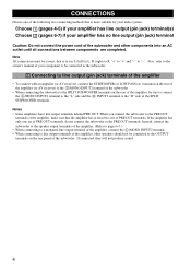
... control panel, this unit consumes a small amount of power. • VOLTAGE SELECTOR (Asia and General models only) The voltage selector switch on the rear panel of this unit must be set for the plug supplied with Canadian ICES-003. 1 This unit features a magnetically shielded design, but there is connected to wide slot and fully insert. PLACEMENT 3 CONNECTIONS 4 1 Connecting to line output (pin jack) terminals of the amplifier 4 2 Connecting to speaker output...
... control panel, this unit consumes a small amount of power. • VOLTAGE SELECTOR (Asia and General models only) The voltage selector switch on the rear panel of this unit must be set for the plug supplied with Canadian ICES-003. 1 This unit features a magnetically shielded design, but there is connected to wide slot and fully insert. PLACEMENT 3 CONNECTIONS 4 1 Connecting to line output (pin jack) terminals of the amplifier 4 2 Connecting to speaker output...
Owner's Manual
Page 6
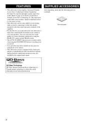
... connecting to either the speaker terminals or the line output (pin jack) terminals of the amplifier. • For the effective use of the subwoofer, the subwoofer's super-bass sound should be matched to the sounds of pressing the STANDBY/ON button to turn the power on Advanced Yamaha Active Servo Technology II.) This super-bass sound adds a more realistic, theater-in four horizontal direction. 2 SUPPLIED ACCESSORIES After unpacking, check that provides smooth bass response...
... connecting to either the speaker terminals or the line output (pin jack) terminals of the amplifier. • For the effective use of the subwoofer, the subwoofer's super-bass sound should be matched to the sounds of pressing the STANDBY/ON button to turn the power on Advanced Yamaha Active Servo Technology II.) This super-bass sound adds a more realistic, theater-in four horizontal direction. 2 SUPPLIED ACCESSORIES After unpacking, check that provides smooth bass response...
Owner's Manual
Page 7
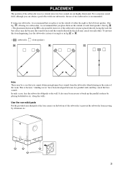
... the four corners on the outside of the subwoofer is because "standing waves" have been developed between two parallel walls and they cancel the bass sounds. PLACEMENT The position of either the right or the left front speaker. (See fig. This is not so critical since low bass sounds are not highly directional. Use the non-skid pads Put the provided...
... the four corners on the outside of the subwoofer is because "standing waves" have been developed between two parallel walls and they cancel the bass sounds. PLACEMENT The position of either the right or the left front speaker. (See fig. This is not so critical since low bass sounds are not highly directional. Use the non-skid pads Put the provided...
Owner's Manual
Page 8
..., refer to the owner's manual of your amplifier has no line output (pin jack) terminal Caution: Do not connect the power cord of the subwoofer and other speakers should not be correct, that the amplifier has at least two sets of PRE OUT terminals. Instead, connect the subwoofer to the speaker output terminals of the amplifier. (Refer to pages 6-7.) • When connecting to a monaural line output terminal of the amplifier, connect the L /MONO...
..., refer to the owner's manual of your amplifier has no line output (pin jack) terminal Caution: Do not connect the power cord of the subwoofer and other speakers should not be correct, that the amplifier has at least two sets of PRE OUT terminals. Instead, connect the subwoofer to the speaker output terminals of the amplifier. (Refer to pages 6-7.) • When connecting to a monaural line output terminal of the amplifier, connect the L /MONO...

Owner's Manual
Page 9
■ Using one subwoofer Subwoofer OUTPUT TO SPEAKERS INPUT 1 FROM AMPLIFIER INPUT PHASE 2 L /MONO NORM REV R AUTO STANDBY HIGH LOW OFF VOLTAGE SELECTOR 220V-240V 110V-120V POWER ON OFF To AC outlet Amplifier OUTPUT TO SPEAKERS INPUT 2 L /MONO R INPUT 1 FROM AMPLIFIER CONNECTIONS Mono pin cable (not included) Audio pin cable (not included) ■ Using two subwoofers OUTPUT TO SPEAKERS INPUT 2 L /MONO Mono pin cable(not included) OUTPUT TO SPEAKERS INPUT 2 L /MONO Subwoofer INPUT 1 FROM AMPLIFIER R Subwoofer OUTPUT TO SPEAKERS INPUT 1 FROM AMPLIFIER INPUT PHASE 2 L /...
■ Using one subwoofer Subwoofer OUTPUT TO SPEAKERS INPUT 1 FROM AMPLIFIER INPUT PHASE 2 L /MONO NORM REV R AUTO STANDBY HIGH LOW OFF VOLTAGE SELECTOR 220V-240V 110V-120V POWER ON OFF To AC outlet Amplifier OUTPUT TO SPEAKERS INPUT 2 L /MONO R INPUT 1 FROM AMPLIFIER CONNECTIONS Mono pin cable (not included) Audio pin cable (not included) ■ Using two subwoofers OUTPUT TO SPEAKERS INPUT 2 L /MONO Mono pin cable(not included) OUTPUT TO SPEAKERS INPUT 2 L /MONO Subwoofer INPUT 1 FROM AMPLIFIER R Subwoofer OUTPUT TO SPEAKERS INPUT 1 FROM AMPLIFIER INPUT PHASE 2 L /...
Owner's Manual
Page 10
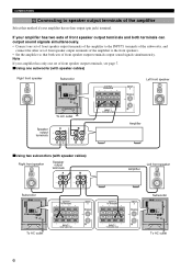
... can output sound signals simultaneously. • Connect one subwoofer (with speaker cables) Right front speaker Subwoofer OUTPUT TO SPEAKERS INPUT 1 FROM AMPLIFIER INPUT PHASE 2 L /MONO NORM REV R AUTO STANDBY HIGH LOW OFF VOLTAGE SELECTOR 220V-240V 110V-120V POWER ON OFF To AC outlet Speaker output terminals OUTPUT TO SPEAKERS INPUT 2 L /MONO Left front speaker INPUT 1 FROM AMPLIFIER R Amplifier ■ Using two subwoofers (with speaker cables) Right front speaker Speaker output terminals Amplifier Left front speaker Subwoofer OUTPUT TO SPEAKERS INPUT 1 FROM AMPLIFIER...
... can output sound signals simultaneously. • Connect one subwoofer (with speaker cables) Right front speaker Subwoofer OUTPUT TO SPEAKERS INPUT 1 FROM AMPLIFIER INPUT PHASE 2 L /MONO NORM REV R AUTO STANDBY HIGH LOW OFF VOLTAGE SELECTOR 220V-240V 110V-120V POWER ON OFF To AC outlet Speaker output terminals OUTPUT TO SPEAKERS INPUT 2 L /MONO Left front speaker INPUT 1 FROM AMPLIFIER R Amplifier ■ Using two subwoofers (with speaker cables) Right front speaker Speaker output terminals Amplifier Left front speaker Subwoofer OUTPUT TO SPEAKERS INPUT 1 FROM AMPLIFIER...
Owner's Manual
Page 11
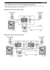
...Using one set of front speaker output terminals. CONNECTIONS If your amplifier has only one subwoofer (with speaker cables) Right front speaker Left front speaker Subwoofer OUTPUT TO SPEAKERS INPUT 1 FROM AMPLIFIER INPUT PHASE 2 L /MONO NORM REV R AUTO STANDBY HIGH LOW OFF VOLTAGE SELECTOR 220V-240V 110V-120V POWER ON OFF OUTPUT TO SPEAKERS INPUT 2 L /MONO R INPUT 1 FROM AMPLIFIER Amplifier To AC outlet Speaker output terminals ■ Using two subwoofers (with speaker cables) Right front speaker Left front speaker Subwoofer OUTPUT TO SPEAKERS INPUT 1 FROM AMPLIFIER INPUT...
...Using one set of front speaker output terminals. CONNECTIONS If your amplifier has only one subwoofer (with speaker cables) Right front speaker Left front speaker Subwoofer OUTPUT TO SPEAKERS INPUT 1 FROM AMPLIFIER INPUT PHASE 2 L /MONO NORM REV R AUTO STANDBY HIGH LOW OFF VOLTAGE SELECTOR 220V-240V 110V-120V POWER ON OFF OUTPUT TO SPEAKERS INPUT 2 L /MONO R INPUT 1 FROM AMPLIFIER Amplifier To AC outlet Speaker output terminals ■ Using two subwoofers (with speaker cables) Right front speaker Left front speaker Subwoofer OUTPUT TO SPEAKERS INPUT 1 FROM AMPLIFIER INPUT...
Owner's Manual
Page 12
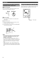
... speaker cable by pulling lightly on the cable at the extremity of each other audio/video components to the AC outlet. OUTPUT TO SPEAKERS INPUT 1 FROM AMPLIFIER INPUT PHASE 2 L /MONO NORM REV R AUTO STANDBY HIGH LOW OFF VOLTAGE SELECTOR 220V-240V 110V-120V POWER ON OFF ■ How to connect 1 Press and hold the terminal's tab, as possible. Good 10mm (3/8") No Good Plug in the subwoofer...
... speaker cable by pulling lightly on the cable at the extremity of each other audio/video components to the AC outlet. OUTPUT TO SPEAKERS INPUT 1 FROM AMPLIFIER INPUT PHASE 2 L /MONO NORM REV R AUTO STANDBY HIGH LOW OFF VOLTAGE SELECTOR 220V-240V 110V-120V POWER ON OFF ■ How to connect 1 Press and hold the terminal's tab, as possible. Good 10mm (3/8") No Good Plug in the subwoofer...
Owner's Manual
Page 13
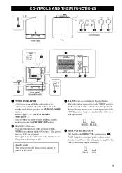
... C OUTPUT TO SPEAKERS INPUT 1 FROM AMPLIFIER INPUT PHASE 2 L /MONO NORM REV R AUTO STANDBY HIGH LOW OFF VOLTAGE SELECTOR 220V-240V 110V-120V POWER ON OFF Rear panel (General model) INPUT 1 FROM AMPLIFIER 0 POWER ON OFF 7 NORM REV R AB 1 POWER INDICATOR Lights up in green while the subwoofer is on the power when the POWER switch is set in the ON position. (The power indicator lights up in red while the subwoofer is set in the standby mode by...
... C OUTPUT TO SPEAKERS INPUT 1 FROM AMPLIFIER INPUT PHASE 2 L /MONO NORM REV R AUTO STANDBY HIGH LOW OFF VOLTAGE SELECTOR 220V-240V 110V-120V POWER ON OFF Rear panel (General model) INPUT 1 FROM AMPLIFIER 0 POWER ON OFF 7 NORM REV R AB 1 POWER INDICATOR Lights up in green while the subwoofer is on the power when the POWER switch is set in the ON position. (The power indicator lights up in red while the subwoofer is set in the standby mode by...
Owner's Manual
Page 14
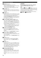
... CUT control Adjusts the high frequency cut off the subwoofer's power supply from the amplifier. (Refer to pages 4 and 5 of "CONNECTIONS" for details.) B PHASE switch Normally this switch to the HIGH or LOW position, the subwoofer's AUTO STANDBY function operates as described on the subwoofer or turn on page 11. Set this switch to the OFF position to be a case when better sound quality is obtained by monitoring the sound. Note...
... CUT control Adjusts the high frequency cut off the subwoofer's power supply from the amplifier. (Refer to pages 4 and 5 of "CONNECTIONS" for details.) B PHASE switch Normally this switch to the HIGH or LOW position, the subwoofer's AUTO STANDBY function operates as described on the subwoofer or turn on page 11. Set this switch to the OFF position to be a case when better sound quality is obtained by monitoring the sound. Note...
Owner's Manual
Page 15
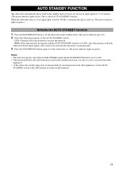
.... • If the subwoofer switches the power on . (The power indicator lights in green.) Activate the AUTO STANDBY function 1 Press the STANDBY/ON button to set the AUTO STANDBY switch to the OFF position to activate this function. - When the subwoofer detects a bass signal input of the AUTO STANDBY switch. - AUTO STANDBY FUNCTION The subwoofer automatically places itself on unexpectedly by receiving noises from other appliances, set the subwoofer in the standby mode. (The power indicator goes off.) 2 Select...
.... • If the subwoofer switches the power on . (The power indicator lights in green.) Activate the AUTO STANDBY function 1 Press the STANDBY/ON button to set the AUTO STANDBY switch to the OFF position to activate this function. - When the subwoofer detects a bass signal input of the AUTO STANDBY switch. - AUTO STANDBY FUNCTION The subwoofer automatically places itself on unexpectedly by receiving noises from other appliances, set the subwoofer in the standby mode. (The power indicator goes off.) 2 Select...
Owner's Manual
Page 16
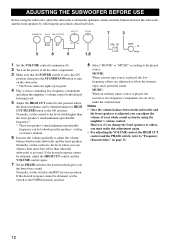
... power of your whole sound system by using the amplifier's volume control. MUSIC: When an ordinary music source is played, the excessive low-frequency components are enhanced to make this adjustment again. • For adjusting the VOLUME control, the HIGH CUT control and the PHASE switch, refer to the position which gives you can obtain a little more bass effect than the front speaker's rated minimum reproducible frequency*. * The front speaker's rated minimum reproducible frequency...
... power of your whole sound system by using the amplifier's volume control. MUSIC: When an ordinary music source is played, the excessive low-frequency components are enhanced to make this adjustment again. • For adjusting the VOLUME control, the HIGH CUT control and the PHASE switch, refer to the position which gives you can obtain a little more bass effect than the front speaker's rated minimum reproducible frequency*. * The front speaker's rated minimum reproducible frequency...
Owner's Manual
Page 17
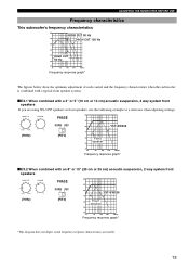
... adjustment of each control and the frequency characteristics when this subwoofer is combined with a typical front speaker system. ■ EX.1 When combined with an 8" or 10" (20 cm or 25 cm) acoustic suspension, 2 way system front speakers (70Hz) PHASE NORM REV (REV) dB 90 80 YST-SW325 70 60 Front speaker 50 40 20 50 100 200 500Hz Frequency response graph* *This diagram...
... adjustment of each control and the frequency characteristics when this subwoofer is combined with a typical front speaker system. ■ EX.1 When combined with an 8" or 10" (20 cm or 25 cm) acoustic suspension, 2 way system front speakers (70Hz) PHASE NORM REV (REV) dB 90 80 YST-SW325 70 60 Front speaker 50 40 20 50 100 200 500Hz Frequency response graph* *This diagram...
Owner's Manual
Page 18
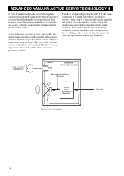
... the marketplace speaker systems utilizing YST (Yamaha Active Servo Technology) to Yamaha Active Servo Technology, allowing better control of view, the speaker impedance changes depending on the sound frequency. This technique uses a direct connection between the speaker cabinet volume and port, it creates more stable performance and clear bass reproduction without any murkiness. Yamaha's newly developed Advanced YST II adds many refinements to give powerful, high quality bass reproduction. From the amplifier's point of...
... the marketplace speaker systems utilizing YST (Yamaha Active Servo Technology) to Yamaha Active Servo Technology, allowing better control of view, the speaker impedance changes depending on the sound frequency. This technique uses a direct connection between the speaker cabinet volume and port, it creates more stable performance and clear bass reproduction without any murkiness. Yamaha's newly developed Advanced YST II adds many refinements to give powerful, high quality bass reproduction. From the amplifier's point of...
Owner's Manual
Page 19
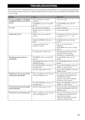
...) to R, "+" to "+" and "-" to "-". Set the PHASE switch to the ON position. The subwoofer turns into the standby mode automatically. Connect them securely. Set the POWER switch to the other position. Otherwise, set to the OFF position. Speaker cables are not connected securely. TROUBLESHOOTING Refer to the chart below do not help, disconnect the power cord and contact your authorized YAMAHA dealer or service center. What to Do Connect it securely.
...) to R, "+" to "+" and "-" to "-". Set the PHASE switch to the ON position. The subwoofer turns into the standby mode automatically. Connect them securely. Set the POWER switch to the other position. Otherwise, set to the OFF position. Speaker cables are not connected securely. TROUBLESHOOTING Refer to the chart below do not help, disconnect the power cord and contact your authorized YAMAHA dealer or service center. What to Do Connect it securely.

Owner's Manual
Page 20
...-VALLEE CEDEX02, FRANCE YAMAHA ELECTRONICS (UK) LTD. Advanced Yamaha Active Servo Technology II Power Consumption 70 W Driver 20 cm (8") cone woofer Magnetic shielding type Amplifier Output (100 Hz, 5 ohms, 10% THD 150 W Standby Power Consumption 0.5 W Dimensions (W x H x D 315 mm x 380 mm x 374 mm (12-3/8" x 14-15/16" x 14-3/4") Frequency Response 25 Hz - 180 Hz Weight 13 kg (28 lbs. 11 oz.) Power Supply USA and Canada models AC 120 V, 60...
...-VALLEE CEDEX02, FRANCE YAMAHA ELECTRONICS (UK) LTD. Advanced Yamaha Active Servo Technology II Power Consumption 70 W Driver 20 cm (8") cone woofer Magnetic shielding type Amplifier Output (100 Hz, 5 ohms, 10% THD 150 W Standby Power Consumption 0.5 W Dimensions (W x H x D 315 mm x 380 mm x 374 mm (12-3/8" x 14-15/16" x 14-3/4") Frequency Response 25 Hz - 180 Hz Weight 13 kg (28 lbs. 11 oz.) Power Supply USA and Canada models AC 120 V, 60...


