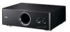
Yamaha FSW150 - YST Subwoofer - 75 Watt Support and Manuals
Get Help and Manuals for this Yamaha item
View All Support Options Below
Free Yamaha FSW150 manuals!
Problems with Yamaha FSW150?
Ask a Question
Free Yamaha FSW150 manuals!
Problems with Yamaha FSW150?
Ask a Question
Yamaha FSW150 Videos

Yamaha Yst-fsw150bl Advanced Yst Ii Down-firing Active Subwoofer
Duration: 1:14
Total Views: 215
Duration: 1:14
Total Views: 215
Popular Yamaha FSW150 Manual Pages
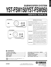
Service Manual - Page 1
... and part
replacement.
Modifications are, therefore, inevitable and specifications are subject to
change without permission. YST-FSW150/ YST-FSW050
SUBWOOFER SYSTEM
YST-FSW150/YST-FSW050
SERVICE MANUAL
• YST-FSW150 • YST-FSW050
IMPORTANT NOTICE
This manual has been provided for the use of YAMAHA are continually striving to improve YAMAHA products. This manual is...
Service Manual - Page 2
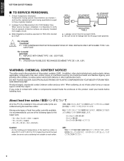
... skin! Leakage Current Measurement (For 120V Models Only) When service has been completed, it is recommended to use a soldering iron suitable to verify that of the lead solder, be replaced with parts having special characteristics are soldered using the lead free solder.
The solder used in both polarities. YST-FSW150/ YST-FSW050
YST-FSW150/YST-FSW050
I TO SERVICE PERSONNEL
1.
Service Manual - Page 3
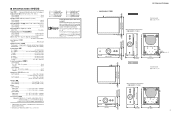
... G, L, J models [YST-FSW050] Black Color U, C, R, T, K, A, B, G, L, J models Silver Color U, C, R, T, K, A, B, G, L, J models Accessories / ଐ
Subwoofer cable (5 m) x 1, System control cable (5 m) x 1, Stand (with PAD x 2) x 1 (YST-FSW150 model),
Screw x 2 (YST-FSW150 model), Nonskid pad x 4
* Specifications are subject to change without notice due to 160 Hz Driver Magnetic...
Service Manual - Page 8
... a flatblade screwdriver is fixed to the cabinet ass'y. b. YST-FSW150/ YST-FSW050
YST-FSW150/YST-FSW050
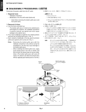
I DISASSEMBLY PROCEDURES
Disconnect the power cable from the AC outlet.
• Required tools •... or the like may cause damage to the bottom grille ass'y. Removal of driver a. When installing the bottom grille ass'y, apply quick-drying bond or the like .)
B
...
Service Manual - Page 9
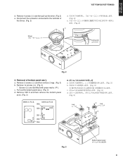
... and then pull out the driver. (Fig. 2) e. Removal of
the Driver. (Fig. 2)
E 1 JHʣ
F JHʣ
1
Driver
$POOFDUPS ίωΫλʔ
Fig. 2
2. Pull out the bottom panel ass'y. (Fig. 3) d. Remove 12 screws (3). (Fig. 3)
* Screws (3) are identified with arrow marks ( ). MAIN (2) P.C.B. YST-FSW150/ YST-FSW050
YST-FSW150/YST-FSW050
d. Disconnect the connector...
Service Manual - Page 10
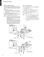
...;ογϡ
Dowel μϘ
Dowel μϘ
Metalblade ϔϥ
YST-FSW050
Flatblade screwdriver
Front panel ass'y 44:
Bushing ϒογϡ
Dowel μ... for secure installation. (The front panel ass'y will come off . (Fig. 4)
Note: • •
Removing the front panel ass'y with
dowels. b. YST-FSW150/ YST-FSW050
YST-FSW150/YST-FSW050
3. Next,...
Service Manual - Page 11
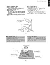
...;"44:
Rear cover ϦΞΧόʔ
5 4
Bushing ϒογϡ
Fig. 5
When Checking the P.C.B.: • Connect all the connectors removed during disassem-
YST-FSW150/ YST-FSW050
YST-FSW150/YST-FSW050
4. d. pose and place the bottom panel ass'y, front panel ass'y and rear panel ass'y on them. (Fig. 6)
1
"44 44 44 JHʣ
Rear panel ass...
Service Manual - Page 12
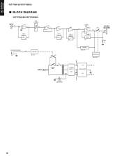
...
S4
3 10
-
12 S0
2 IC3
+
9
-B
A.N.IC IC2
DRIVER WOOFER
+
R59 0.1
SYSTEM CONTROL +10
JK1
DRIVER Q10,11
AC IN
LIMITER Q5,6,7,8
RY2
POWER SW1
+B
F1 T1
POWER SUPPLY
D20 AC5
IC4 REGULATOR
IC5
D1
-B POWER INDICATOR
PROTECTION Q2,4,9,12 +15
-15
12
YST-FSW150/ YST-FSW050
YST-FSW150/YST-FSW050
I BLOCK DIAGRAM
YST-FSW150/YST-FSW050
INPUT
S1
PJ1
IC1A
6S2 5 +
7
VR1 VOLUME
S3...
Service Manual - Page 13
... H1 D19 H3 Q14 I1 D20 F2
CB4
SP- DRIVER
SP+
WOOFER
C56 G3
B, G models
W10B1
W10B2
W10B3
W10B1
W10B2
W10B3
13 A
B
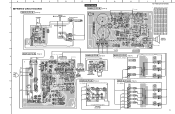
1 I PRINTED CIRCUIT BOARDS
MAIN (3) P.C.B. (Side A)
VOLUME
2
1
8
S3
3
E S2
+15
-15
LEDG
LED
IC1 W2
C
D
E
F
G
YST-FSW150 MAIN (1) P.C.B. (Side A)
POWER OFF/SYSTEM ON
Power indicator
IC3 12
H
B, G models 1
W3A
WH
W3B
BE
IC2
8
1
W10A3 W10A2 W10A1...
Service Manual - Page 14
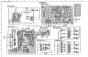
DRIVER
SP+
WOOFER
C56
K, B, G models G3
W10B3
W10B2
W10B1
W10B3
W10B2
W10B1 Location Ref no .
A
B
C
YST-FSW150/YST-FSW050
1
MAIN (3) P.C.B. (Side A)
VOLUME
2
1
IC1 W2
8
S3
3
E S2
+15
-15 LEDG
LED
D
E
F
G
YST-FSW050 MAIN (1) P.C.B. (Side A)
POWER
12
OFF/SYSTEM ON
Power indicator
H
K, B, G models IC3
1
W3A
WH
W3B
BE
IC2
8
1
W10A3 W10A2 W10A1
W9
W8
...
Service Manual - Page 15
...voltages are measured with a 10MΩ/V DC electronic voltmeter. # Components having special characteristics are marked s and must be replaced
with parts having specifications equal to those originally installed. # Schematic diagram is subject to change without notice.
15 A
B
C
D
E
F
G
H
I
J
K
L
M
N
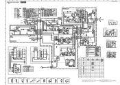
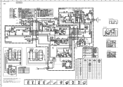
SCHEMATIC DIAGRAMS YST-FSW150
MAIN
1
YST-FSW150/YST-FSW050
MAIN (1)
POWER AMP.
Service Manual - Page 16
... L models)
MAIN (8)
W11B
POWER TRANSFORMER
W7B
W10B1
W12B
7 W13B
W10B2
W14B
W6B
W10B3
W6A
8
W7A
MAIN (6)
CB12
CB11
W13A
W11A
9
W14A
W12A
VOLTAGE SELECTOR
# All voltages are measured with a 10MΩ/V DC electronic voltmeter.
# Components having special characteristics are marked s and must be replaced
with parts having specifications equal to those originally installed.
10...
Service Manual - Page 17
....RT
: ROTARY SWITCH
SW.SLIDE : SLIDE SWITCH
TERM.SP : SPEAKER TERMINAL
TERM.WRAP : WRAPPING TERMINAL
THRMST.CHP : CHIP THERMISTOR
TR....YST-FSW150/ YST-FSW050
YST-FSW150/YST-FSW050
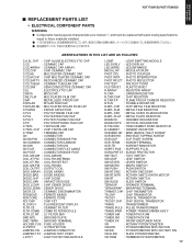
I REPLACEMENT PARTS LIST
• ELECTRICAL COMPONENT PARTS
WARNING G Components having special characteristics are marked s and must be replaced with parts having specifications
equal to those originally installed...
Service Manual - Page 22
...B 5
R, L models
8-19 *2
8-1 (8) 6
8-1 (6)
Packing B
8-11
8-19 *2 8-1 (2)
8-26
23
23
8-37
8-11 9
8-34
36
8-32 8-32 8-31
8-37
7
22
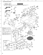
placement parts. Be sure to use...available as specified below. To replace packing B, C and D, use a new bushing in place of packing as re- A
B
C
D
E
YST-FSW150/YST-FSW050
1
• OVERALL ASS'Y
YST-FSW150
*1 Used bushing, once ...
Service Manual - Page 24
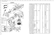
... packing as replacement parts.
35 203
To replace packing C, D and G. A
B
C
D
E
YST-FSW150/YST-FSW050
1
YST-FSW050
*1 Used bushing...229mm x 6mm (9" x 1/4")
Packing D:
83mm x 6mm (3-1/4" x 1/4")
23 8-4
Packing G: 114mm x 6mm (4-1/2" x 1/4")
8-32
Packing G
R, L models
6 8-26
8-1 (6)
Packing G
8-1 (8)
8-11
23
8-11
9
8-34 36
7
8-19 *2
8-32
8-1 (2) 23
8-32 8-31
8-37
8-37...
Yamaha FSW150 Reviews
We have not received any reviews for Yamaha yet.