Service Manual
Page 1
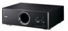
..., inevitable and specifications are already known and understood by an authorized YAMAHA Retailer or the appointed service representative. YST-FSW150/ YST-FSW050 SUBWOOFER SYSTEM YST-FSW150/YST-FSW050 SERVICE MANUAL • YST-FSW150 • YST-FSW050 IMPORTANT NOTICE This manual has been provided for the use of the... constitute authorization, certification or recognition of any applicable technical capabilities, or establish a principle-agent relationship of YAMAHA are continually striving to the unit(s) indicated on the cover. IMPORTANT: The presentation or sale of this...
..., inevitable and specifications are already known and understood by an authorized YAMAHA Retailer or the appointed service representative. YST-FSW150/ YST-FSW050 SUBWOOFER SYSTEM YST-FSW150/YST-FSW050 SERVICE MANUAL • YST-FSW150 • YST-FSW050 IMPORTANT NOTICE This manual has been provided for the use of the... constitute authorization, certification or recognition of any applicable technical capabilities, or establish a principle-agent relationship of YAMAHA are continually striving to the unit(s) indicated on the cover. IMPORTANT: The presentation or sale of this...
Service Manual
Page 2
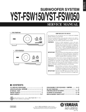
... also contain traces of this product, wash your skin! WARNING: CHEMICAL CONTENT NOTICE! Avoid prolonged, unprotected contact between solder and your hands before handling food. YST-FSW150/ YST-FSW050 YST-FSW150/YST-FSW050 I TO SERVICE PERSONNEL 1. The solder used in both polarities. In addition, other reproductive harm. Among some types of lead free solder currently available, it is...
... also contain traces of this product, wash your skin! WARNING: CHEMICAL CONTENT NOTICE! Avoid prolonged, unprotected contact between solder and your hands before handling food. YST-FSW150/ YST-FSW050 YST-FSW150/YST-FSW050 I TO SERVICE PERSONNEL 1. The solder used in both polarities. In addition, other reproductive harm. Among some types of lead free solder currently available, it is...
Service Manual
Page 3
...; (100 Hz, 5 ohms, 10% T.H.D.) [YST-FSW150 75 W [YST-FSW050 50 W Dynamic Power 5 ohms) [YST-FSW150 130 W [YST-FSW050 100 W Input Sensitivity 50 Hz, 75 W / 5 ohms, INPUT (PJ)) [YST-FSW150 100 mV [YST-FSW050 50 mV Input Impedance INPUT (PJ 12 k-ohms Frequency Response YST-FSW150 30 Hz to 160 Hz [YST-FSW050 35 Hz to product improvements. U.S.A. General model T .......... Singapore model J Japanese model Advanced Yamaha Active Servo Tech- nology...
...; (100 Hz, 5 ohms, 10% T.H.D.) [YST-FSW150 75 W [YST-FSW050 50 W Dynamic Power 5 ohms) [YST-FSW150 130 W [YST-FSW050 100 W Input Sensitivity 50 Hz, 75 W / 5 ohms, INPUT (PJ)) [YST-FSW150 100 mV [YST-FSW050 50 mV Input Impedance INPUT (PJ 12 k-ohms Frequency Response YST-FSW150 30 Hz to 160 Hz [YST-FSW050 35 Hz to product improvements. U.S.A. General model T .......... Singapore model J Japanese model Advanced Yamaha Active Servo Tech- nology...
Service Manual
Page 8
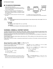
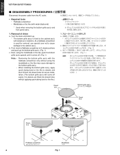
... the like to dowels and then fit them into dowel holes for removal, use special care not to cause damage to the bottom grille ass'y. YST-FSW150/ YST-FSW050 YST-FSW150/YST-FSW050 I DISASSEMBLY PROCEDURES Disconnect the power cable from the AC outlet. • Required tools • Flatblade screwdriver • Metalblade or the like (with dowels at 4 locations...
... the like to dowels and then fit them into dowel holes for removal, use special care not to cause damage to the bottom grille ass'y. YST-FSW150/ YST-FSW050 YST-FSW150/YST-FSW050 I DISASSEMBLY PROCEDURES Disconnect the power cable from the AC outlet. • Required tools • Flatblade screwdriver • Metalblade or the like (with dowels at 4 locations...
Service Manual
Page 9
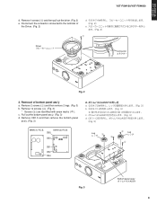
...;ωΫλʔ Fig. 2 2. c. Remove 12 screws (3). (Fig. 3) * Screws (3) are identified with arrow marks ( ). MAIN (2) P.C.B. Remove 4 screws (1) and then pull out the driver. (Fig. 2) e. YST-FSW150/ YST-FSW050 YST-FSW150/YST-FSW050 d.
...;ωΫλʔ Fig. 2 2. c. Remove 12 screws (3). (Fig. 3) * Screws (3) are identified with arrow marks ( ). MAIN (2) P.C.B. Remove 4 screws (1) and then pull out the driver. (Fig. 2) e. YST-FSW150/ YST-FSW050 YST-FSW150/YST-FSW050 d.
Service Manual
Page 10
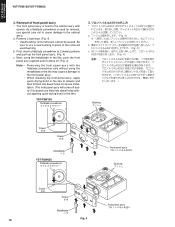
..."44 JH 44 44 44 44 44 Bushing ϒογϡ Dowel μϘ Dowel μϘ Metalblade ϔϥ YST-FSW050 Flatblade screwdriver Front panel ass'y 44: Bushing ϒογϡ Dowel μϘ Dowel μϘ Metalblade ϔϥ Front...Fig. 4) c. a. Be sure to use a new bushing in place of front panel ass'y * The front panel ass'y is used bushing. YST-FSW150/ YST-FSW050 YST-FSW150/YST-FSW050 3. Removal of the removed used for secure installation. (The front panel ass'y will come off . (Fig. 4) Note: • • ...
..."44 JH 44 44 44 44 44 Bushing ϒογϡ Dowel μϘ Dowel μϘ Metalblade ϔϥ YST-FSW050 Flatblade screwdriver Front panel ass'y 44: Bushing ϒογϡ Dowel μϘ Dowel μϘ Metalblade ϔϥ Front...Fig. 4) c. a. Be sure to use a new bushing in place of front panel ass'y * The front panel ass'y is used bushing. YST-FSW150/ YST-FSW050 YST-FSW150/YST-FSW050 3. Removal of the removed used for secure installation. (The front panel ass'y will come off . (Fig. 4) Note: • • ...
Service Manual
Page 11
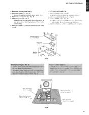
... removed during disassem- Be sure to the original positions. • Spread the rubber sheet and cloth for insulation pur- Removal of the removed used bushing. YST-FSW150/ YST-FSW050 YST-FSW150/YST-FSW050 4.
... removed during disassem- Be sure to the original positions. • Spread the rubber sheet and cloth for insulation pur- Removal of the removed used bushing. YST-FSW150/ YST-FSW050 YST-FSW150/YST-FSW050 4.
Service Manual
Page 12
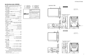
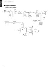
IC6A 3+ 1 - L.P.F. 12dB/oct IC6B 5+ 7 - H.P.F. 12dB/oct POWER AMP. +B RY1 S4 3 10 - 12 S0 2 IC3 + 9 -B A.N.IC IC2 DRIVER WOOFER + R59 0.1 SYSTEM CONTROL +10 JK1 DRIVER Q10,11 AC IN LIMITER Q5,6,7,8 RY2 POWER SW1 +B F1 T1 POWER SUPPLY D20 AC5 IC4 REGULATOR IC5 D1 -B POWER INDICATOR PROTECTION Q2,4,9,12 +15 -15 12 YST-FSW150/ YST-FSW050 YST-FSW150/YST-FSW050 I BLOCK DIAGRAM YST-FSW150/YST-FSW050 INPUT S1 PJ1 IC1A 6S2 5 + 7 VR1 VOLUME S3 L.P.F. 6dB/oct 3 + IC1B 1 2-
IC6A 3+ 1 - L.P.F. 12dB/oct IC6B 5+ 7 - H.P.F. 12dB/oct POWER AMP. +B RY1 S4 3 10 - 12 S0 2 IC3 + 9 -B A.N.IC IC2 DRIVER WOOFER + R59 0.1 SYSTEM CONTROL +10 JK1 DRIVER Q10,11 AC IN LIMITER Q5,6,7,8 RY2 POWER SW1 +B F1 T1 POWER SUPPLY D20 AC5 IC4 REGULATOR IC5 D1 -B POWER INDICATOR PROTECTION Q2,4,9,12 +15 -15 12 YST-FSW150/ YST-FSW050 YST-FSW150/YST-FSW050 I BLOCK DIAGRAM YST-FSW150/YST-FSW050 INPUT S1 PJ1 IC1A 6S2 5 + 7 VR1 VOLUME S3 L.P.F. 6dB/oct 3 + IC1B 1 2-
Service Manual
Page 13
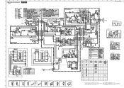
...W10B1 W10B2 W10B3 13 Location Ref no . A B 1 I PRINTED CIRCUIT BOARDS MAIN (3) P.C.B. (Side A) VOLUME 2 1 8 S3 3 E S2 +15 -15 LEDG LED IC1 W2 C D E F G YST-FSW150 MAIN (1) P.C.B. (Side A) POWER OFF/SYSTEM ON Power indicator IC3 12 H B, G models 1 W3A WH W3B BE IC2 8 1 W10A3 W10A2 W10A1 W9 W8 MAIN (2) P.C.B. (Side A) 4 BE WH...RE BR BE BE W11B W7B W12B W13B W14B W6B W6B W7B AC5 -B 15G +B -15 +15 R1B R1A E3 PRT SO E S4 I J YST-FSW150/YST-FSW050 • Semiconductor Location Ref no . Location D1 D2 IC1 C3 D3 C5 IC2 G3 D4 C6 IC3 G1 D5 D7 IC4 C5 D6 B7 IC5...
...W10B1 W10B2 W10B3 13 Location Ref no . A B 1 I PRINTED CIRCUIT BOARDS MAIN (3) P.C.B. (Side A) VOLUME 2 1 8 S3 3 E S2 +15 -15 LEDG LED IC1 W2 C D E F G YST-FSW150 MAIN (1) P.C.B. (Side A) POWER OFF/SYSTEM ON Power indicator IC3 12 H B, G models 1 W3A WH W3B BE IC2 8 1 W10A3 W10A2 W10A1 W9 W8 MAIN (2) P.C.B. (Side A) 4 BE WH...RE BR BE BE W11B W7B W12B W13B W14B W6B W6B W7B AC5 -B 15G +B -15 +15 R1B R1A E3 PRT SO E S4 I J YST-FSW150/YST-FSW050 • Semiconductor Location Ref no . Location D1 D2 IC1 C3 D3 C5 IC2 G3 D4 C6 IC3 G1 D5 D7 IC4 C5 D6 B7 IC5...
Service Manual
Page 14
... I1 IC1 C3 CB4 SP- DRIVER SP+ WOOFER C56 K, B, G models G3 W10B3 W10B2 W10B1 W10B3 W10B2 W10B1 Location Ref no . A B C YST-FSW150/YST-FSW050 1 MAIN (3) P.C.B. (Side A) VOLUME 2 1 IC1 W2 8 S3 3 E S2 +15 -15 LEDG LED D E F G YST-FSW050 MAIN (1) P.C.B. (Side A) POWER 12 OFF/SYSTEM ON Power indicator H K, B, G models IC3 1 W3A WH W3B BE IC2 8 1 W10A3 W10A2 W10A1...
... I1 IC1 C3 CB4 SP- DRIVER SP+ WOOFER C56 K, B, G models G3 W10B3 W10B2 W10B1 W10B3 W10B2 W10B1 Location Ref no . A B C YST-FSW150/YST-FSW050 1 MAIN (3) P.C.B. (Side A) VOLUME 2 1 IC1 W2 8 S3 3 E S2 +15 -15 LEDG LED D E F G YST-FSW050 MAIN (1) P.C.B. (Side A) POWER 12 OFF/SYSTEM ON Power indicator H K, B, G models IC3 1 W3A WH W3B BE IC2 8 1 W10A3 W10A2 W10A1...
Service Manual
Page 15
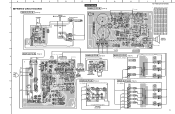
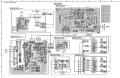
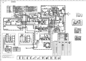
... marked s and must be replaced with parts having specifications equal to those originally installed. # Schematic diagram is subject to change without notice. 15 A B C D E F G H I J K L M N SCHEMATIC DIAGRAMS YST-FSW150 MAIN 1 YST-FSW150/YST-FSW050 MAIN (1) POWER AMP.
... marked s and must be replaced with parts having specifications equal to those originally installed. # Schematic diagram is subject to change without notice. 15 A B C D E F G H I J K L M N SCHEMATIC DIAGRAMS YST-FSW150 MAIN 1 YST-FSW150/YST-FSW050 MAIN (1) POWER AMP.
Service Manual
Page 16
... D3SBA20 4A 200V 1 2 34 NJM4558L 1 NJM78M15FA NJM79M15FA STK404-120 8 12 3: IN 3: COM 1: OUT 2: COM 1: OUT 2: IN 1 V723510 JG-11-T FG64410 0.01/50 FG65122 22P O O A B C D E F G H I J K L M N YST-FSW150/YST-FSW050 1 MAIN YST-FSW050 2 INPUT 3 JK1 SYSTEM CONNECTOR 4 L.P.F. +15.0 0 IC1 0 0 5 MAIN (3) 6 (R, L models) MAIN (8) W11B POWER TRANSFORMER W7B W10B1 W12B 7 W13B W10B2 W14B W6B W10B3 W6A 8 W7A MAIN (6) CB12 CB11...
... D3SBA20 4A 200V 1 2 34 NJM4558L 1 NJM78M15FA NJM79M15FA STK404-120 8 12 3: IN 3: COM 1: OUT 2: COM 1: OUT 2: IN 1 V723510 JG-11-T FG64410 0.01/50 FG65122 22P O O A B C D E F G H I J K L M N YST-FSW150/YST-FSW050 1 MAIN YST-FSW050 2 INPUT 3 JK1 SYSTEM CONNECTOR 4 L.P.F. +15.0 0 IC1 0 0 5 MAIN (3) 6 (R, L models) MAIN (8) W11B POWER TRANSFORMER W7B W10B1 W12B 7 W13B W10B2 W14B W6B W10B3 W6A 8 W7A MAIN (6) CB12 CB11...
Service Manual
Page 17
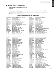
YST-FSW150/ YST-FSW050 YST-FSW150/YST-FSW050 I REPLACEMENT PARTS LIST • ELECTRICAL COMPONENT PARTS WARNING G Components having special characteristics are marked s and must be replaced with parts having specifications equal to those ...
YST-FSW150/ YST-FSW050 YST-FSW150/YST-FSW050 I REPLACEMENT PARTS LIST • ELECTRICAL COMPONENT PARTS WARNING G Components having special characteristics are marked s and must be replaced with parts having specifications equal to those ...
Service Manual
Page 22
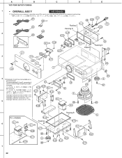
... D 204 203 4 *2 Packing B, C and D are not available as specified below. To replace packing B, C and D, use a new bushing in place of packing as re- placement parts. A B C D E YST-FSW150/YST-FSW050 1 • OVERALL ASS'Y YST-FSW150 *1 Used bushing, once removed, cannot be reused.
... D 204 203 4 *2 Packing B, C and D are not available as specified below. To replace packing B, C and D, use a new bushing in place of packing as re- placement parts. A B C D E YST-FSW150/YST-FSW050 1 • OVERALL ASS'Y YST-FSW150 *1 Used bushing, once removed, cannot be reused.
Service Manual
Page 24
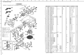
...;οΩϯɹ̖ Ψεέοτ ÷ø ÷ø ÷ø ÷ø Ϩοά ÷ù ÷ø A B C D E YST-FSW150/YST-FSW050 1 YST-FSW050 *1 Used bushing, once removed, cannot be reused.
...;οΩϯɹ̖ Ψεέοτ ÷ø ÷ø ÷ø ÷ø Ϩοά ÷ù ÷ø A B C D E YST-FSW150/YST-FSW050 1 YST-FSW050 *1 Used bushing, once removed, cannot be reused.