
Owner's Manual
Page 2
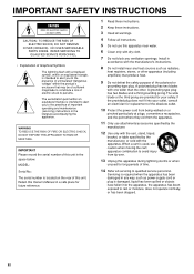
... openings. II NO USER-SERVICEABLE PARTS INSIDE. MODEL: Serial No.: The serial number is damaged, liquid has been spilled or objects have fallen into your safety. Install in a safe place for replacement of the obsolete outlet. 10 Protect the power cord from being walked on the rear of important operating and maintenance (servicing) instructions in the space below. If the provided plug does not fit...
... openings. II NO USER-SERVICEABLE PARTS INSIDE. MODEL: Serial No.: The serial number is damaged, liquid has been spilled or objects have fallen into your safety. Install in a safe place for replacement of the obsolete outlet. 10 Protect the power cord from being walked on the rear of important operating and maintenance (servicing) instructions in the space below. If the provided plug does not fit...
Owner's Manual
Page 3
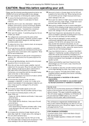
... equipment generates/uses radio frequencies and, if not installed and used . and, most out of your equipment by Yamaha Corporation of other electronic devices. Since hearing damage from excessive volume levels. If this product is often undetectable until it at a safe level. Utilize power outlets that is 300 ohm ribbon lead, change the lead-in to avoid prolonged exposure from loud sounds is...
... equipment generates/uses radio frequencies and, if not installed and used . and, most out of your equipment by Yamaha Corporation of other electronic devices. Since hearing damage from excessive volume levels. If this product is often undetectable until it at a safe level. Utilize power outlets that is 300 ohm ribbon lead, change the lead-in to avoid prolonged exposure from loud sounds is...
Owner's Manual
Page 5
...rear panel of this unit for selecting this YAMAHA Subwoofer System. If the object falls or drops by vibrations, it might cause an electric shock since this unit away from the TV set in order not to allow spaces of at high volume level. Standby mode When this unit is turned off from the AC line only when the POWER switch is the owner... injury. If something drops into the YST port located on switches, controls or connection wires. are continuously outputted at least 20 cm above , behind and on the floor or other equipment. YAMAHA shall not be the same as this...
...rear panel of this unit for selecting this YAMAHA Subwoofer System. If the object falls or drops by vibrations, it might cause an electric shock since this unit away from the TV set in order not to allow spaces of at high volume level. Standby mode When this unit is turned off from the AC line only when the POWER switch is the owner... injury. If something drops into the YST port located on switches, controls or connection wires. are continuously outputted at least 20 cm above , behind and on the floor or other equipment. YAMAHA shall not be the same as this...
Owner's Manual
Page 6
... STANDBY/ON button to either the speaker terminals or the line output (pin jack) terminals of the amplifier. ● For the effective use of the H.P.F. OUTPUT terminals 8 Ground connection 10 Connecting the AC power cable 11 NOTES ABOUT THE REMOTE CONTROL 11 CONTROLS AND THEIR FUNCTIONS 12 AUTOMATIC POWER-SWITCHING FUNCTION 14 ADJUSTING THE SUBWOOFER BEFORE USE 15 Storing preset data of the VOLUME control etc 16 Frequency characteristics 17 ADVANCED YAMAHA ACTIVE SERVO TECHNOLOGY 18 TROUBLESHOOTING 19 SPECIFICATIONS...
... STANDBY/ON button to either the speaker terminals or the line output (pin jack) terminals of the amplifier. ● For the effective use of the H.P.F. OUTPUT terminals 8 Ground connection 10 Connecting the AC power cable 11 NOTES ABOUT THE REMOTE CONTROL 11 CONTROLS AND THEIR FUNCTIONS 12 AUTOMATIC POWER-SWITCHING FUNCTION 14 ADJUSTING THE SUBWOOFER BEFORE USE 15 Storing preset data of the VOLUME control etc 16 Frequency characteristics 17 ADVANCED YAMAHA ACTIVE SERVO TECHNOLOGY 18 TROUBLESHOOTING 19 SPECIFICATIONS...
Owner's Manual
Page 8
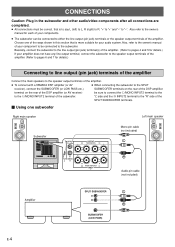
Choose one subwoofer Right main speaker Left main speaker Subwoofer REMOTE AUTO STANDBY HIGH OFF OUTPUT INPUT LOW H.P.F.OUTPUT 80Hz 100Hz H.P.F.OUTPUT LFE NORMAL /MONO OUTPUT TO SPEAKERS GND INPUT INPUT 3 2 FROM AMPLIFIER INPUT 1 80Hz 100Hz LFE NORMAL /MONO GND AC IN POWER ON OFF INPUT INPUT 3 2 OUTPUT TO SPEAKERS FROM AMPLIFIER INPUT 1 Mono pin cable (not included) Audio pin cable (not included) Amplifier SPLIT SUBWOOFER SUBWOOFER (LOW PASS) E-4 Also, refer to the owner's manual of your component to be sure to connect the L/MONO INPUT2 terminal to the...
Choose one subwoofer Right main speaker Left main speaker Subwoofer REMOTE AUTO STANDBY HIGH OFF OUTPUT INPUT LOW H.P.F.OUTPUT 80Hz 100Hz H.P.F.OUTPUT LFE NORMAL /MONO OUTPUT TO SPEAKERS GND INPUT INPUT 3 2 FROM AMPLIFIER INPUT 1 80Hz 100Hz LFE NORMAL /MONO GND AC IN POWER ON OFF INPUT INPUT 3 2 OUTPUT TO SPEAKERS FROM AMPLIFIER INPUT 1 Mono pin cable (not included) Audio pin cable (not included) Amplifier SPLIT SUBWOOFER SUBWOOFER (LOW PASS) E-4 Also, refer to the owner's manual of your component to be sure to connect the L/MONO INPUT2 terminal to the...
Owner's Manual
Page 9
... amplifier has only one set of the subwoofer. If connected, they will bring you connect the subwoofer to the OUTPUT terminals on the rear panel of PRE OUT terminals, do not connect the subwoofer to the subwoofer's LFE (INPUT3) terminal(s). English Ⅵ Using two subwoofers Right main speaker Left main speaker Mono pin cables (not included) H.P.F.OUTPUT 80Hz 100Hz LFE NORMAL /MONO OUTPUT H.P.F.OUTPUT TO SPEAKERS 80Hz 100Hz LFE NORMAL /MONO OUTPUT TO SPEAKERS GND INPUT INPUT 3 2 Right subwoofer REMOTE AUTO STANDBY OUTPUT INPUT HIGH LOW...
... amplifier has only one set of the subwoofer. If connected, they will bring you connect the subwoofer to the OUTPUT terminals on the rear panel of PRE OUT terminals, do not connect the subwoofer to the subwoofer's LFE (INPUT3) terminal(s). English Ⅵ Using two subwoofers Right main speaker Left main speaker Mono pin cables (not included) H.P.F.OUTPUT 80Hz 100Hz LFE NORMAL /MONO OUTPUT H.P.F.OUTPUT TO SPEAKERS 80Hz 100Hz LFE NORMAL /MONO OUTPUT TO SPEAKERS GND INPUT INPUT 3 2 Right subwoofer REMOTE AUTO STANDBY OUTPUT INPUT HIGH LOW...

Owner's Manual
Page 10
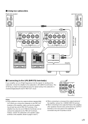
... speaker output terminals Right main speaker Subwoofer REMOTE AUTO STANDBY OUTPUT INPUT HIGH LOW OFF H.P.F.OUTPUT 80Hz 100Hz H.P.F.OUTPUT LFE NORMAL /MONO OUTPUT TO SPEAKERS GND INPUT INPUT 3 2 FROM AMPLIFIER INPUT 1 80Hz 100Hz LFE NORMAL /MONO GND AC IN POWER ON OFF INPUT INPUT 3 2 OUTPUT TO SPEAKERS FROM AMPLIFIER INPUT 1 Left main speaker Speaker output terminals A B Amplifier (Both A and B speaker outputs must be ON.) E-6 Connecting to speaker output terminals of the amplifier Ⅵ Using one set of main speaker output terminals Connect the speaker output...
... speaker output terminals Right main speaker Subwoofer REMOTE AUTO STANDBY OUTPUT INPUT HIGH LOW OFF H.P.F.OUTPUT 80Hz 100Hz H.P.F.OUTPUT LFE NORMAL /MONO OUTPUT TO SPEAKERS GND INPUT INPUT 3 2 FROM AMPLIFIER INPUT 1 80Hz 100Hz LFE NORMAL /MONO GND AC IN POWER ON OFF INPUT INPUT 3 2 OUTPUT TO SPEAKERS FROM AMPLIFIER INPUT 1 Left main speaker Speaker output terminals A B Amplifier (Both A and B speaker outputs must be ON.) E-6 Connecting to speaker output terminals of the amplifier Ⅵ Using one set of main speaker output terminals Connect the speaker output...
Owner's Manual
Page 11
... INPUT 1 INPUT INPUT 3 2 OUTPUT TO SPEAKERS FROM AMPLIFIER INPUT 1 Amplifier Left subwoofer REMOTE AUTO STANDBY OUTPUT INPUT HIGH LOW OFF H.P.F.OUTPUT 80Hz 100Hz LFE NORMAL /MONO GND INPUT INPUT 3 2 OUTPUT TO SPEAKERS FROM AMPLIFIER INPUT 1 AC IN POWER ON OFF Speaker output terminals Connecting to the INPUT1/OUTPUT terminals of them . If the connections are observed and set correctly. English Ⅵ Using two subwoofers Connect the speaker output terminals of the amplifier to the INPUT1 terminals of the subwoofer, and connect the OUTPUT terminals of the cables...
... INPUT 1 INPUT INPUT 3 2 OUTPUT TO SPEAKERS FROM AMPLIFIER INPUT 1 Amplifier Left subwoofer REMOTE AUTO STANDBY OUTPUT INPUT HIGH LOW OFF H.P.F.OUTPUT 80Hz 100Hz LFE NORMAL /MONO GND INPUT INPUT 3 2 OUTPUT TO SPEAKERS FROM AMPLIFIER INPUT 1 AC IN POWER ON OFF Speaker output terminals Connecting to the INPUT1/OUTPUT terminals of them . If the connections are observed and set correctly. English Ⅵ Using two subwoofers Connect the speaker output terminals of the amplifier to the INPUT1 terminals of the subwoofer, and connect the OUTPUT terminals of the cables...

Owner's Manual
Page 12
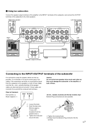
... speaker Left main speaker Subwoofer REMOTE AUTO STANDBY OUTPUT INPUT HIGH LOW OFF H.P.F.OUTPUT 80Hz 100Hz LFE NORMAL /MONO GND INPUT INPUT 3 2 OUTPUT TO SPEAKERS FROM AMPLIFIER INPUT 1 H.P.F.OUTPUT 80Hz 100Hz LFE NORMAL /MONO GND INPUT INPUT 3 2 AC IN POWER ON OFF Audio pin cable (not included) OUTPUT TO SPEAKERS FROM AMPLIFIER INPUT 1 Audio pin cable (not included) PRE OUT MAIN IN Amplifier E-8 Connecting to H.P.F. OUTPUT terminals The use of the subwoofer cut off frequencies below the selected frequency point from the input signals, and output high frequencies...
... speaker Left main speaker Subwoofer REMOTE AUTO STANDBY OUTPUT INPUT HIGH LOW OFF H.P.F.OUTPUT 80Hz 100Hz LFE NORMAL /MONO GND INPUT INPUT 3 2 OUTPUT TO SPEAKERS FROM AMPLIFIER INPUT 1 H.P.F.OUTPUT 80Hz 100Hz LFE NORMAL /MONO GND INPUT INPUT 3 2 AC IN POWER ON OFF Audio pin cable (not included) OUTPUT TO SPEAKERS FROM AMPLIFIER INPUT 1 Audio pin cable (not included) PRE OUT MAIN IN Amplifier E-8 Connecting to H.P.F. OUTPUT terminals The use of the subwoofer cut off frequencies below the selected frequency point from the input signals, and output high frequencies...

Owner's Manual
Page 13
.... OUTPUT switch. (Normally, it is made, select the desired frequency point (80 Hz or 100 Hz) with the H.P.F. English Ⅵ To connect two units Right main speaker Left main speaker Mono pin cables (not included) H.P.F.OUTPUT 80Hz 100Hz LFE NORMAL /MONO OUTPUT TO SPEAKERS H.P.F.OUTPUT 80Hz 100Hz LFE NORMAL /MONO OUTPUT TO SPEAKERS GND Right subwoofer REMOTE AUTO STANDBY OUTPUT INPUT HIGH LOW OFF H.P.F.OUTPUT 80Hz 100Hz LFE NORMAL /MONO GND INPUT INPUT 3 2 OUTPUT TO SPEAKERS FROM AMPLIFIER INPUT 1 INPUT INPUT 3 2 GND FROM AMPLIFIER INPUT...
.... OUTPUT switch. (Normally, it is made, select the desired frequency point (80 Hz or 100 Hz) with the H.P.F. English Ⅵ To connect two units Right main speaker Left main speaker Mono pin cables (not included) H.P.F.OUTPUT 80Hz 100Hz LFE NORMAL /MONO OUTPUT TO SPEAKERS H.P.F.OUTPUT 80Hz 100Hz LFE NORMAL /MONO OUTPUT TO SPEAKERS GND Right subwoofer REMOTE AUTO STANDBY OUTPUT INPUT HIGH LOW OFF H.P.F.OUTPUT 80Hz 100Hz LFE NORMAL /MONO GND INPUT INPUT 3 2 OUTPUT TO SPEAKERS FROM AMPLIFIER INPUT 1 INPUT INPUT 3 2 GND FROM AMPLIFIER INPUT...

Owner's Manual
Page 14
...cover of the receiver/amplifier to the rear panel as shown in Illustration B. Subwoofer Insert Tighten Grounding cable REMOTE AUTO STANDBY HIGH OFF OUTPUT INPUT LOW H.P.F.OUTPUT 80Hz 100Hz LFE NORMAL /MONO GND INPUT INPUT 3 2 OUTPUT TO SPEAKERS FROM AMPLIFIER INPUT 1 " DIGITAL OUTPUT MD/ TAPE CD-R OPTICAL CD CD-R DVD D-TV /LD SIGNAL GND OPTICAL COAXIAL CD RS232C CBL /SAT LD RF (AC-3) COAXIAL: SELECT BY SETMENU DIGITAL INPUT AUDIO R L R IN (PLAY) MD/TAPE OUT (REC) IN (PLAY) CD-R OUT (REC) CD PHONO MAIN SURROUND SUB CENTER WOOFER 6CH INPUT # Metal part PHONO...
...cover of the receiver/amplifier to the rear panel as shown in Illustration B. Subwoofer Insert Tighten Grounding cable REMOTE AUTO STANDBY HIGH OFF OUTPUT INPUT LOW H.P.F.OUTPUT 80Hz 100Hz LFE NORMAL /MONO GND INPUT INPUT 3 2 OUTPUT TO SPEAKERS FROM AMPLIFIER INPUT 1 " DIGITAL OUTPUT MD/ TAPE CD-R OPTICAL CD CD-R DVD D-TV /LD SIGNAL GND OPTICAL COAXIAL CD RS232C CBL /SAT LD RF (AC-3) COAXIAL: SELECT BY SETMENU DIGITAL INPUT AUDIO R L R IN (PLAY) MD/TAPE OUT (REC) IN (PLAY) CD-R OUT (REC) CD PHONO MAIN SURROUND SUB CENTER WOOFER 6CH INPUT # Metal part PHONO...

Owner's Manual
Page 15
... not connect the included power cable to avoid direct lighting. Plug in the power cable to the wall outlet. Notes ● Use only AA, R6, UM-3 batteries for an extended period of time. ● If batteries leak, dispose of the subwoofer, and then plug in the subwoofer to the main unit, the batteries are weak. E-11 model) To AC outlet NOTES ABOUT THE REMOTE CONTROL Battery installation Remote control operation range 3 1 2 Remote control...
... not connect the included power cable to avoid direct lighting. Plug in the power cable to the wall outlet. Notes ● Use only AA, R6, UM-3 batteries for an extended period of time. ● If batteries leak, dispose of the subwoofer, and then plug in the subwoofer to the main unit, the batteries are weak. E-11 model) To AC outlet NOTES ABOUT THE REMOTE CONTROL Battery installation Remote control operation range 3 1 2 Remote control...

Owner's Manual
Page 16
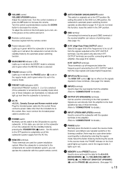
... AC IN 0 Rear panel REMOTE AUTO STANDBY HIGH OFF OUTPUT INPUT LOW H.P.F.OUTPUT 80Hz 100Hz LFE NORMAL /MONO GND INPUT INPUT 3 2 OUTPUT TO SPEAKERS FROM AMPLIFIER INPUT 1 POWER ON OFF AC IN POWER ON OFF q t yu i REMOTE AUTO STANDBY HIGH OFF OUTPUT INPUT LOW H.P.F.OUTPUT 80Hz 100Hz LFE NORMAL /MONO GND INPUT INPUT 3 2 wer OUTPUT TO SPEAKERS FROM AMPLIFIER INPUT 1 o Remote control 1 2 p a 3 4 1 STANDBY/ON button Press this switch to select the MOVIE mode, the bass sound in video software is still using a small amount of the frequencies to turn it.
... AC IN 0 Rear panel REMOTE AUTO STANDBY HIGH OFF OUTPUT INPUT LOW H.P.F.OUTPUT 80Hz 100Hz LFE NORMAL /MONO GND INPUT INPUT 3 2 OUTPUT TO SPEAKERS FROM AMPLIFIER INPUT 1 POWER ON OFF AC IN POWER ON OFF q t yu i REMOTE AUTO STANDBY HIGH OFF OUTPUT INPUT LOW H.P.F.OUTPUT 80Hz 100Hz LFE NORMAL /MONO GND INPUT INPUT 3 2 wer OUTPUT TO SPEAKERS FROM AMPLIFIER INPUT 1 o Remote control 1 2 p a 3 4 1 STANDBY/ON button Press this switch to select the MOVIE mode, the bass sound in video software is still using a small amount of the frequencies to turn it.
Owner's Manual
Page 17
... turn on the signals inputted to these terminals. (See page 5 for details.) H OUTPUT (TO SPEAKERS) terminals Can be cut off the subwoofer's power supply from the input signals and output higher frequencies. Lights up in the reverse mode. 9 PRESET 1/2/3 indicators (LED) Show which PRESET number (1, 2 or 3) is selected. (If the subwoofer is turned into the standby mode by monitoring the sound. Use this button to the main speakers by the H.P.F. To adjust the control on page 14. Set this switch...
... turn on the signals inputted to these terminals. (See page 5 for details.) H OUTPUT (TO SPEAKERS) terminals Can be cut off the subwoofer's power supply from the input signals and output higher frequencies. Lights up in the reverse mode. 9 PRESET 1/2/3 indicators (LED) Show which PRESET number (1, 2 or 3) is selected. (If the subwoofer is turned into the standby mode by monitoring the sound. Use this button to the main speakers by the H.P.F. To adjust the control on page 14. Set this switch...

Owner's Manual
Page 18
... set the switch to the OFF position. * This function detects the low-frequency components below 200 Hz of the input signals (i.e., the explosion in the action movie, the sound of the subwoofer turns on the front panel goes off for 7 to 8 minutes, the subwoofer automatically switches to the standby mode. (When the subwoofer switches to the standby mode by the automatic powerswitching function, the power indicator lights up in red.) When you play a source again, the power...
... set the switch to the OFF position. * This function detects the low-frequency components below 200 Hz of the input signals (i.e., the explosion in the action movie, the sound of the subwoofer turns on the front panel goes off for 7 to 8 minutes, the subwoofer automatically switches to the standby mode. (When the subwoofer switches to the standby mode by the automatic powerswitching function, the power indicator lights up in red.) When you play a source again, the power...
Owner's Manual
Page 19
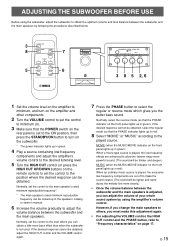
... not used. However, if you change the main speakers to the played source. HIGH CUT VOLUME 40Hz 140Hz 0 10 3 8 5 2, 6 1 Set the volume level on the amplifier to minimum, and turn on the subwoofer. * The power indicator lights up in green. 4 Play a source containing low-frequency components and adjust the amplifier's volume control to the desired listening level. 5 Turn the HIGH CUT control (or press the HIGH CUT UP/DOWN buttons on the front panel lights up in red). 8 Select "MOVIE" or "MUSIC...
... not used. However, if you change the main speakers to the played source. HIGH CUT VOLUME 40Hz 140Hz 0 10 3 8 5 2, 6 1 Set the volume level on the amplifier to minimum, and turn on the subwoofer. * The power indicator lights up in green. 4 Play a source containing low-frequency components and adjust the amplifier's volume control to the desired listening level. 5 Turn the HIGH CUT control (or press the HIGH CUT UP/DOWN buttons on the front panel lights up in red). 8 Select "MOVIE" or "MUSIC...
Owner's Manual
Page 20
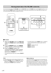
... Yamaha speaker system with this function, you can recall any preset data easily according to store (and recall) one set of the VOLUME control, the HIGH CUT control, the PHASE button and the B.A.S.S. The PRESET number indicators on the remote control is used to the source. 1 2 3 SUBWOOFER SYSTEM YST-SW1500 PRESET MUSIC/MOVIE PHASE 1 2 3 STANDBY/ON B.A.S.S. If, however, the power is lost even if the POWER switch is set . PRESET 1: NS-8HX, NS-6HX PRESET 2: NS-4HX PRESET...
... Yamaha speaker system with this function, you can recall any preset data easily according to store (and recall) one set of the VOLUME control, the HIGH CUT control, the PHASE button and the B.A.S.S. The PRESET number indicators on the remote control is used to the source. 1 2 3 SUBWOOFER SYSTEM YST-SW1500 PRESET MUSIC/MOVIE PHASE 1 2 3 STANDBY/ON B.A.S.S. If, however, the power is lost even if the POWER switch is set . PRESET 1: NS-8HX, NS-6HX PRESET 2: NS-4HX PRESET...

Owner's Manual
Page 21
... The figures below show the optimum adjustment of each control and the frequency characteristics when this subwoofer is combined with a 4" or 5" (10 cm or 13 cm) acoustic suspension, 2 way system main speakers HIGH CUT VOLUME 100 dB 90 40Hz 140Hz 0 10 PHASE-Set to the reverse mode. B.A.S.S.-MOVIE 80 YST-SW1500 70 60 Main speaker's response 50 40 20 50 100...
... The figures below show the optimum adjustment of each control and the frequency characteristics when this subwoofer is combined with a 4" or 5" (10 cm or 13 cm) acoustic suspension, 2 way system main speakers HIGH CUT VOLUME 100 dB 90 40Hz 140Hz 0 10 PHASE-Set to the reverse mode. B.A.S.S.-MOVIE 80 YST-SW1500 70 60 Main speaker's response 50 40 20 50 100...
Owner's Manual
Page 22
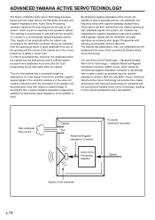
... impedance converter to select an optimum value for subtracting output impedance of frequencies with superior damping characteristics. The system can provide more natural and dynamic bass reproduction. Our new Active Servo Technology - To accomplish this opening as high-amplitude signals. Advanced Yamaha Active Servo Technology - ADVANCED YAMAHA ACTIVE SERVO TECHNOLOGY The theory of low amplitude E-18 Active Servo Processing speakers reproduce the bass frequencies...
... impedance converter to select an optimum value for subtracting output impedance of frequencies with superior damping characteristics. The system can provide more natural and dynamic bass reproduction. Our new Active Servo Technology - To accomplish this opening as high-amplitude signals. Advanced Yamaha Active Servo Technology - ADVANCED YAMAHA ACTIVE SERVO TECHNOLOGY The theory of low amplitude E-18 Active Servo Processing speakers reproduce the bass frequencies...
Owner's Manual
Page 23
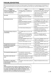
... set to the subwoofer. Set the AUTO STANDBY switch to the chart below do not help, disconnect the power cable and contact your authorized YAMAHA dealer or service center. English TROUBLESHOOTING Refer to the "HIGH" or "LOW" position. along the walls. The subwoofer turns into the standby mode automatically . The distance or range within which the remote control can be used decreases. A source sound with bass frequencies. Move the subwoofer farther away from external appliances etc. Set the POWER switch...
... set to the subwoofer. Set the AUTO STANDBY switch to the chart below do not help, disconnect the power cable and contact your authorized YAMAHA dealer or service center. English TROUBLESHOOTING Refer to the "HIGH" or "LOW" position. along the walls. The subwoofer turns into the standby mode automatically . The distance or range within which the remote control can be used decreases. A source sound with bass frequencies. Move the subwoofer farther away from external appliances etc. Set the POWER switch...


