
Owner's Manual
Page 2
... radiators, heat registers, stoves, or other . A grounding type plug has two blades and a third grounding prong. Install in any way, such as power-supply cord or plug is required when the apparatus has been damaged in accordance with the manufacturer's instructions. 8 Do not install near water. 6 Clean only... blade or the third prong are provided for your outlet, consult an electrician for long periods of the obsolete outlet. 10 Protect the power cable from being walked on or pinched particularly at plugs, convenience receptacles, and the point where they exit from tip-over. 13 Unplug...
... radiators, heat registers, stoves, or other . A grounding type plug has two blades and a third grounding prong. Install in any way, such as power-supply cord or plug is required when the apparatus has been damaged in accordance with the manufacturer's instructions. 8 Do not install near water. 6 Clean only... blade or the third prong are provided for your outlet, consult an electrician for long periods of the obsolete outlet. 10 Protect the power cable from being walked on or pinched particularly at plugs, convenience receptacles, and the point where they exit from tip-over. 13 Unplug...

Owner's Manual
Page 3
...locate the appropriate retailer, please contact YAMAHA Electronics Corp., U.S.A. 6660 Orangethorpe Ave...You Listening For A Lifetime YAMAHA and the Electronic Industries Association...of your equipment by YAMAHA may cause interference harmful ...YAMAHA Corporation of radio or TV interference, relocate/reorient the antenna. Failure to avoid prolonged exposure from loud sounds is often undetectable until it at a safe level. Utilize power outlets that lets the sound... that is too late, YAMAHA and the Electronic Industries Association... THIS UNIT! Cable/s supplied with these corrective measures ...
...locate the appropriate retailer, please contact YAMAHA Electronics Corp., U.S.A. 6660 Orangethorpe Ave...You Listening For A Lifetime YAMAHA and the Electronic Industries Association...of your equipment by YAMAHA may cause interference harmful ...YAMAHA Corporation of radio or TV interference, relocate/reorient the antenna. Failure to avoid prolonged exposure from loud sounds is often undetectable until it at a safe level. Utilize power outlets that lets the sound... that is too late, YAMAHA and the Electronic Industries Association... THIS UNIT! Cable/s supplied with these corrective measures ...

Owner's Manual
Page 4
... clean place with the letter N or coloured BLACK. YAMAHA will form when the surrounding temperature changes suddenly. The cabinet should be connected to avoid humming sounds. 4 Do not expose this unit, and/or personal injury. - vacation), disconnect the AC power plug from the wall outlet. 15 Be sure to hot... used. This Class B digital apparatus complies with chemical solvents; MODEL: Serial No.: The serial number is connected to the AC wall outlet, even if this unit - Retain this unit must be cut off , then leave the unit alone for the plug supplied with this appliance, it ...
... clean place with the letter N or coloured BLACK. YAMAHA will form when the surrounding temperature changes suddenly. The cabinet should be connected to avoid humming sounds. 4 Do not expose this unit, and/or personal injury. - vacation), disconnect the AC power plug from the wall outlet. 15 Be sure to hot... used. This Class B digital apparatus complies with chemical solvents; MODEL: Serial No.: The serial number is connected to the AC wall outlet, even if this unit - Retain this unit must be cut off , then leave the unit alone for the plug supplied with this appliance, it ...

Owner's Manual
Page 5
... a TV 15 Connecting a DVD player/recorder 16 Connecting a VCR 17 Connecting a digital satellite tuner or a cable TV tuner 18 Connecting other external components 19 Connecting a subwoofer 20 Connecting the power supply cable 21 SETUP GETTING STARTED 22 Installing batteries in the remote control 22 Operation range...timer 55 Canceling the sleep timer 56 ADVANCED OPERATION BASIC SETUP 57 MANUAL SETUP 63 Using MANUAL SETUP 64 BEAM MENU 65 SOUND MENU 69 INPUT MENU 71 DISPLAY MENU 73 ADJUSTING SYSTEM PARAMETERS ...........75 Setting the maximum volume level 75 Protecting the current...
... a TV 15 Connecting a DVD player/recorder 16 Connecting a VCR 17 Connecting a digital satellite tuner or a cable TV tuner 18 Connecting other external components 19 Connecting a subwoofer 20 Connecting the power supply cable 21 SETUP GETTING STARTED 22 Installing batteries in the remote control 22 Operation range...timer 55 Canceling the sleep timer 56 ADVANCED OPERATION BASIC SETUP 57 MANUAL SETUP 63 Using MANUAL SETUP 64 BEAM MENU 65 SOUND MENU 69 INPUT MENU 71 DISPLAY MENU 73 ADJUSTING SYSTEM PARAMETERS ...........75 Setting the maximum volume level 75 Protecting the current...

Owner's Manual
Page 8
...page 82. 4 See "GETTING STARTED" on page 26. 5 Play back a source and enjoy surround sound. See "CONNECTIONS" on page 14. 3 Prepare the remote control and turn on page 11. 2 ...this unit in your listening room. In case of improvements, etc. See "INSTALLATION" on the power of external components, refer to change in part as a result of differences between the manual and...See "AUTO SETUP" on page 22. 4 Run AUTO SETUP. Design and specifications are subject to the supplied owner's manual for the component. • Some operations can be performed by using remote control operation. ...
...page 82. 4 See "GETTING STARTED" on page 26. 5 Play back a source and enjoy surround sound. See "CONNECTIONS" on page 14. 3 Prepare the remote control and turn on page 11. 2 ...this unit in your listening room. In case of improvements, etc. See "INSTALLATION" on the power of external components, refer to change in part as a result of differences between the manual and...See "AUTO SETUP" on page 22. 4 Run AUTO SETUP. Design and specifications are subject to the supplied owner's manual for the component. • Some operations can be performed by using remote control operation. ...
Owner's Manual
Page 9
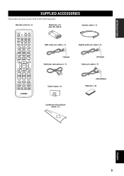
... cable (×1) STANDBY/ON POWER POWER AV TV DVD AUX VCR INPUT1 STB TV INPUT2 TV MACRO YSP 5BEAM 1 INPUTMODE SLEEP ST+3BEAM 2 3BEAM 3 STEREO TARGET 4 5 6 MUSIC 7 MOVIE 8 VOL MODE 9 SPORTS 0 OFF +10 SURROUND CH LEVEL CINEMA DSP MENU TEST ENTER RETURN VOLUME CH TV VOL OSD video pin cable (×1) Digital audio pin cable (×...
... cable (×1) STANDBY/ON POWER POWER AV TV DVD AUX VCR INPUT1 STB TV INPUT2 TV MACRO YSP 5BEAM 1 INPUTMODE SLEEP ST+3BEAM 2 3BEAM 3 STEREO TARGET 4 5 6 MUSIC 7 MOVIE 8 VOL MODE 9 SPORTS 0 OFF +10 SURROUND CH LEVEL CINEMA DSP MENU TEST ENTER RETURN VOLUME CH TV VOL OSD video pin cable (×1) Digital audio pin cable (×...

Owner's Manual
Page 10
...23). CONTROLS AND FUNCTIONS CONTROLS AND FUNCTIONS Front panel 1 2 3 4 5 6 INPUT VOLUME + STANDBY/ON 1 OPTIMIZER MIC jack Use to connect the supplied optimizer microphone to be a 4 to 5-second delay before it to switch between input sources (TV, VCR, DVD or AUX). Notes • When you ...2 Front panel display Shows information about the operational status of this unit or sets it can reproduce sound. • In the standby mode, this unit consumes a small amount of power in order to receive infrared-signals from the remote control. 4 INPUT Press repeatedly to the standby ...
...23). CONTROLS AND FUNCTIONS CONTROLS AND FUNCTIONS Front panel 1 2 3 4 5 6 INPUT VOLUME + STANDBY/ON 1 OPTIMIZER MIC jack Use to connect the supplied optimizer microphone to be a 4 to 5-second delay before it to switch between input sources (TV, VCR, DVD or AUX). Notes • When you ...2 Front panel display Shows information about the operational status of this unit or sets it can reproduce sound. • In the standby mode, this unit consumes a small amount of power in order to receive infrared-signals from the remote control. 4 INPUT Press repeatedly to the standby ...

Owner's Manual
Page 12
...) Use to connect a YAMAHA subwoofer equipped with a SYSTEM CONNECTOR jack to this unit (see page 15). 5 TV/STB OPTICAL DIGITAL INPUT jack Use to connect a TV, digital satellite tuner and cable TV tuner via an optical digital connection (see pages 15 and 18). 6 AUX OPTICAL DIGITAL INPUT jack Use to connect... terminal of your TV to display the OSD of this unit (see page 20). 9 AC power supply cable Use to connect to connect a DVD player via an optical digital connection (see page 19). 7 DVD COAXIAL DIGITAL INPUT jack Use to the AC wall outlet (see page 16). 8 SYSTEM CONNECTOR jack (U.S.A.
...) Use to connect a YAMAHA subwoofer equipped with a SYSTEM CONNECTOR jack to this unit (see page 15). 5 TV/STB OPTICAL DIGITAL INPUT jack Use to connect a TV, digital satellite tuner and cable TV tuner via an optical digital connection (see pages 15 and 18). 6 AUX OPTICAL DIGITAL INPUT jack Use to connect... terminal of your TV to display the OSD of this unit (see page 20). 9 AC power supply cable Use to connect to connect a DVD player via an optical digital connection (see page 19). 7 DVD COAXIAL DIGITAL INPUT jack Use to the AC wall outlet (see page 16). 8 SYSTEM CONNECTOR jack (U.S.A.

Owner's Manual
Page 17
... the top of the rack, etc. This unit Fasteners Peel off the film from each of the four supplied fasteners and then secure them to a dirty or wet surface will weaken the sticking power of the tape, and this unit may fall as a result. ■ Affixing this unit Peel off 2 the film...
... the top of the rack, etc. This unit Fasteners Peel off the film from each of the four supplied fasteners and then secure them to a dirty or wet surface will weaken the sticking power of the tape, and this unit may fall as a result. ■ Affixing this unit Peel off 2 the film...

Owner's Manual
Page 24
...(see page 26) or select SWFR for connections Subwoofer pin cable TV/STB AUX OPTICAL DVD COAXIAL DIGITAL INPUT SYSTEM CONNECTOR System connector cable (supplied with the YAMAHA subwoofer with a SYSTEM CONNECTOR jack, connect it to the SYSTEM CONNECTOR jack (U.S.A. If the subwoofer ...CONNECTOR jack on this unit. and Canada models only) When connecting a YAMAHA subwoofer equipped with the SYSTEM CONNECTOR jack) 20 Subwoofer Monaural System input connector Rear panel of this unit controls the power mode of this unit (U.S.A. CONNECTIONS Connecting a subwoofer To connect a ...
...(see page 26) or select SWFR for connections Subwoofer pin cable TV/STB AUX OPTICAL DVD COAXIAL DIGITAL INPUT SYSTEM CONNECTOR System connector cable (supplied with the YAMAHA subwoofer with a SYSTEM CONNECTOR jack, connect it to the SYSTEM CONNECTOR jack (U.S.A. If the subwoofer ...CONNECTOR jack on this unit. and Canada models only) When connecting a YAMAHA subwoofer equipped with the SYSTEM CONNECTOR jack) 20 Subwoofer Monaural System input connector Rear panel of this unit controls the power mode of this unit (U.S.A. CONNECTIONS Connecting a subwoofer To connect a ...

Owner's Manual
Page 25
CONNECTIONS To the AC outlet PREPARATION English 21 Connecting the power supply cable Once all other connections are complete, plug the power supply cable into the AC wall outlet.
CONNECTIONS To the AC outlet PREPARATION English 21 Connecting the power supply cable Once all other connections are complete, plug the power supply cable into the AC wall outlet.

Owner's Manual
Page 32
VOLUME + STANDBY/ON 1 2 STANDBY/ON POWER POWER AV TV 3 4 DVD VCR STB TV AUX INPUT1 INPUT2 MACRO YSP ( ) INPUTMODE SLEEP 5BEAM 1 ST+3BEAM 2 3BEAM 3 STEREO UNIVERSAL 4 5 6 MUSIC 7 MOVIE 8 NIGHT 9 SPORTS 0 OFF +10 SURROUND CH LEVEL CINEMA DSP MENU 1 Disassemble the three parts of the ...your listening room, follow the procedure below to start the AUTO SETUP procedure. AUTO SETUP Example of using the supplied cardboard microphone stand Optimizer microphone position Within 1 m (3.3 ft) More than 2 m (6.5 ft) Within 1 m (3.3 ft) Cardboard microphone ...
VOLUME + STANDBY/ON 1 2 STANDBY/ON POWER POWER AV TV 3 4 DVD VCR STB TV AUX INPUT1 INPUT2 MACRO YSP ( ) INPUTMODE SLEEP 5BEAM 1 ST+3BEAM 2 3BEAM 3 STEREO UNIVERSAL 4 5 6 MUSIC 7 MOVIE 8 NIGHT 9 SPORTS 0 OFF +10 SURROUND CH LEVEL CINEMA DSP MENU 1 Disassemble the three parts of the ...your listening room, follow the procedure below to start the AUTO SETUP procedure. AUTO SETUP Example of using the supplied cardboard microphone stand Optimizer microphone position Within 1 m (3.3 ft) More than 2 m (6.5 ft) Within 1 m (3.3 ft) Cardboard microphone ...

Owner's Manual
Page 42
...power of your TV and DVD player, you can use the remote control supplied with this unit. Note This section uses a DVD player as stereo sources) changes at the minimum volume level. The numeric value of the playback source. DVD Adjusting the volume INPUT VOLUME + STANDBY/ON VOLUME CH... the appropriate remote control codes for your TV until you cannot hear any sound. 4 Press DVD on how to around -25 dB. • If...page 37), you can play back the selected input source. Audio signals from the speakers of this unit to select DVD as the input source. y • If the...
...power of your TV and DVD player, you can use the remote control supplied with this unit. Note This section uses a DVD player as stereo sources) changes at the minimum volume level. The numeric value of the playback source. DVD Adjusting the volume INPUT VOLUME + STANDBY/ON VOLUME CH... the appropriate remote control codes for your TV until you cannot hear any sound. 4 Press DVD on how to around -25 dB. • If...page 37), you can play back the selected input source. Audio signals from the speakers of this unit to select DVD as the input source. y • If the...

Owner's Manual
Page 57
4 Press / on the remote control or if you disconnect the power supply cable from the AC wall outlet. USING THE VOLUME MODE BASIC OPERATION English 53 Note The volume mode settings are canceled if you press STANDBY/ON on the front panel or on the remote control to adjust the effect level of compression while NIGHT:CINEMA, NIGHT:MUSIC or TV EQUAL VOL is displayed. ENTER Effect.Lvl:MIN Effect.Lvl:MID Effect.Lvl:MAX • Select Effect.Lvl:MIN for minimum compression. • Select Effect.Lvl:MID for standard compression. • Select Effect.Lvl:MAX for maximum compression.
4 Press / on the remote control or if you disconnect the power supply cable from the AC wall outlet. USING THE VOLUME MODE BASIC OPERATION English 53 Note The volume mode settings are canceled if you press STANDBY/ON on the front panel or on the remote control to adjust the effect level of compression while NIGHT:CINEMA, NIGHT:MUSIC or TV EQUAL VOL is displayed. ENTER Effect.Lvl:MIN Effect.Lvl:MID Effect.Lvl:MAX • Select Effect.Lvl:MIN for minimum compression. • Select Effect.Lvl:MID for standard compression. • Select Effect.Lvl:MAX for maximum compression.

Owner's Manual
Page 91
...standby mode, disconnect the power cord and contact the nearest authorized YAMAHA dealer or service center. ■ General Problem Cause Remedy This unit fails to turn it back on. has been activated. The volume is muted. The sound is turned down and ... of the center speaker. No sound from the center speaker. Connect the power supply cable firmly to minimum. No sound Incorrect input or output cable connections. Signals this unit. speakers. to FRONT when a Dolby Digital or DTS signal is Raise the level of the center speaker is being received ...
...standby mode, disconnect the power cord and contact the nearest authorized YAMAHA dealer or service center. ■ General Problem Cause Remedy This unit fails to turn it back on. has been activated. The volume is muted. The sound is turned down and ... of the center speaker. No sound from the center speaker. Connect the power supply cable firmly to minimum. No sound Incorrect input or output cable connections. Signals this unit. speakers. to FRONT when a Dolby Digital or DTS signal is Raise the level of the center speaker is being received ...

Owner's Manual
Page 92
...panel display.) The connected component is not set to the digital or high-frequency equipment. Select SWFR for your component. Select TV as the input source. Connect the cable properly. Disconnect the AC power cable from such equipment. This unit is Set CROSS OVER ...power supply with strong bass elements was played back. Disable surround effect settings on this unit further away from the outlet and then plug it in SUBWOOFER SET is too close to output Dolby Digital or DTS digital signals. There is set incorrectly. The protection circuitry was in the path of the sound...
...panel display.) The connected component is not set to the digital or high-frequency equipment. Select SWFR for your component. Select TV as the input source. Connect the cable properly. Disconnect the AC power cable from such equipment. This unit is Set CROSS OVER ...power supply with strong bass elements was played back. Disable surround effect settings on this unit further away from the outlet and then plug it in SUBWOOFER SET is too close to output Dolby Digital or DTS digital signals. There is set incorrectly. The protection circuitry was in the path of the sound...

Owner's Manual
Page 96
...220-240 V, 50/60 Hz • Power Consumption 30 W • Standby Power Consumption 0.1 W or less • Dimensions (W x H x D 800 × 153 × 115 mm ...Digital) • Output Jacks SUBWOOFER OUT (1.5 V, less than 120 Hz) ...... 1 (Subwoofer) VIDEO OUT (1 Vp-p, 75 1 (OSD) • System Connector Jack OPTIMIZER MIC 1 (Microphone input) SYSTEM CONNECTOR 1 (System control) GENERAL • Power Supply [U.S.A. SPECIFICATIONS SPECIFICATIONS AMP SECTION • Maximum Output Power (EIAJ 2 W (1 kHz, 10% THD, 4 Ω) × 21 20 W (100 Hz, 10% THD, 4 Ω) × 2 SPEAKER...
...220-240 V, 50/60 Hz • Power Consumption 30 W • Standby Power Consumption 0.1 W or less • Dimensions (W x H x D 800 × 153 × 115 mm ...Digital) • Output Jacks SUBWOOFER OUT (1.5 V, less than 120 Hz) ...... 1 (Subwoofer) VIDEO OUT (1 Vp-p, 75 1 (OSD) • System Connector Jack OPTIMIZER MIC 1 (Microphone input) SYSTEM CONNECTOR 1 (System control) GENERAL • Power Supply [U.S.A. SPECIFICATIONS SPECIFICATIONS AMP SECTION • Maximum Output Power (EIAJ 2 W (1 kHz, 10% THD, 4 Ω) × 21 20 W (100 Hz, 10% THD, 4 Ω) × 2 SPEAKER...

Owner's Manual
Page 101
...sound...speakers, turn down the volume level using the remote control supplied with your TV until you hear sound output from your TV using the remote control supplied with adjustable volume and crossover/high cut frequency to -40 dB. The results of the beam mode buttons on the power...CH...supplied...speakers...CH LEVEL CINEMA DSP MENU TEST ENTER RETURN PREPARATION . AUX YSP INPUT1 INPUT2 MACRO INPUTMODE SLEEP 6 Press one of the five...supplied OSD video pin cable to the video input 2 jack of sound...to select BEAM OPT+SOUND OPTIMZ and then ...CH TV VOL 5 Press YSP...CH TV VOL 5 Press YSP...
...sound...speakers, turn down the volume level using the remote control supplied with your TV until you hear sound output from your TV using the remote control supplied with adjustable volume and crossover/high cut frequency to -40 dB. The results of the beam mode buttons on the power...CH...supplied...speakers...CH LEVEL CINEMA DSP MENU TEST ENTER RETURN PREPARATION . AUX YSP INPUT1 INPUT2 MACRO INPUTMODE SLEEP 6 Press one of the five...supplied OSD video pin cable to the video input 2 jack of sound...to select BEAM OPT+SOUND OPTIMZ and then ...CH TV VOL 5 Press YSP...CH TV VOL 5 Press YSP...


