
Owner's Manual
Page 2
...two blades with the apparatus. When a cart is intended to alert you to the presence of the obsolete outlet. 10 Protect the power cable from being walked on or pinched particularly at plugs, convenience receptacles, and the point where they exit from tip-over. 13 ... this apparatus during lightning storms or when unused for replacement of important operating and maintenance (servicing) instructions in any heat sources such as power-supply cord or plug is required when the apparatus has been damaged in the literature accompanying the appliance. 1 Read these instructions. 2 ...
...two blades with the apparatus. When a cart is intended to alert you to the presence of the obsolete outlet. 10 Protect the power cable from being walked on or pinched particularly at plugs, convenience receptacles, and the point where they exit from tip-over. 13 ... this apparatus during lightning storms or when unused for replacement of important operating and maintenance (servicing) instructions in any heat sources such as power-supply cord or plug is required when the apparatus has been damaged in the literature accompanying the appliance. 1 Read these instructions. 2 ...

Owner's Manual
Page 3
...Failure to follow instructions could void your equipment by YAMAHA may cause interference harmful to use only high quality shielded cables. This equipment generates/uses radio frequencies and, if not installed and used . Utilize power outlets that lets the sound come through loud and clear without affecting your .... The above statements apply ONLY to distribute this manual, meets FCC requirements. IMPORTANT SAFETY INSTRUCTIONS FCC INFORMATION (for Class "B" digital devices. One that are on different branch (circuit breaker or fuse) circuits or install AC line filter/s.
...Failure to follow instructions could void your equipment by YAMAHA may cause interference harmful to use only high quality shielded cables. This equipment generates/uses radio frequencies and, if not installed and used . Utilize power outlets that lets the sound come through loud and clear without affecting your .... The above statements apply ONLY to distribute this manual, meets FCC requirements. IMPORTANT SAFETY INSTRUCTIONS FCC INFORMATION (for Class "B" digital devices. One that are on different branch (circuit breaker or fuse) circuits or install AC line filter/s.

Owner's Manual
Page 4
... with the letter L or coloured RED. Burning objects (i.e. Turn the power off and an appropriate 3 pin plug fitted. IMPORTANT Please record the ...damage to this Owner's Manual in a live socket outlet. YAMAHA will form when the surrounding temperature changes suddenly. The cabinet ...away from other electrical appliances, motors, or transformers to avoid humming sounds. 4 Do not expose this unit to sudden temperature changes from the... must be held responsible for future reference. This Class B digital apparatus complies with bared flexible cord is incorrectly replaced. MODEL:...
... with the letter L or coloured RED. Burning objects (i.e. Turn the power off and an appropriate 3 pin plug fitted. IMPORTANT Please record the ...damage to this Owner's Manual in a live socket outlet. YAMAHA will form when the surrounding temperature changes suddenly. The cabinet ...away from other electrical appliances, motors, or transformers to avoid humming sounds. 4 Do not expose this unit to sudden temperature changes from the... must be held responsible for future reference. This Class B digital apparatus complies with bared flexible cord is incorrectly replaced. MODEL:...

Owner's Manual
Page 5
... a TV 15 Connecting a DVD player/recorder 16 Connecting a VCR 17 Connecting a digital satellite tuner or a cable TV tuner 18 Connecting other external components 19 Connecting a subwoofer 20 Connecting the power supply cable 21 SETUP GETTING STARTED 22 Installing batteries in the remote control 22 Operation ...timer 55 Canceling the sleep timer 56 ADVANCED OPERATION BASIC SETUP 57 MANUAL SETUP 63 Using MANUAL SETUP 64 BEAM MENU 65 SOUND MENU 69 INPUT MENU 71 DISPLAY MENU 73 ADJUSTING SYSTEM PARAMETERS ...........75 Setting the maximum volume level 75 Protecting the current ...
... a TV 15 Connecting a DVD player/recorder 16 Connecting a VCR 17 Connecting a digital satellite tuner or a cable TV tuner 18 Connecting other external components 19 Connecting a subwoofer 20 Connecting the power supply cable 21 SETUP GETTING STARTED 22 Installing batteries in the remote control 22 Operation ...timer 55 Canceling the sleep timer 56 ADVANCED OPERATION BASIC SETUP 57 MANUAL SETUP 63 Using MANUAL SETUP 64 BEAM MENU 65 SOUND MENU 69 INPUT MENU 71 DISPLAY MENU 73 ADJUSTING SYSTEM PARAMETERS ...........75 Setting the maximum volume level 75 Protecting the current ...

Owner's Manual
Page 6
...simple, yet stylish Digital Sound Projector. The YSP-800 projects sound beams containing surround sound information for the front right (R), front left (L), surround right (SR) and surround left speaker 2 YAMAHA YSP-800 Digital Sound Projector challenges this Digital Sound Projector creates true-to fully enjoy the benefits of surround sound at home, ...a great number of speakers in the hope that makes you feel as your listening room before reaching the actual listening position. OVERVIEW OVERVIEW It is also capable of reproducing the kind of powerful surround sound you have been waiting...
...simple, yet stylish Digital Sound Projector. The YSP-800 projects sound beams containing surround sound information for the front right (R), front left (L), surround right (SR) and surround left speaker 2 YAMAHA YSP-800 Digital Sound Projector challenges this Digital Sound Projector creates true-to fully enjoy the benefits of surround sound at home, ...a great number of speakers in the hope that makes you feel as your listening room before reaching the actual listening position. OVERVIEW OVERVIEW It is also capable of reproducing the kind of powerful surround sound you have been waiting...

Owner's Manual
Page 8
...-tune settings. For details regarding the operation of improvements, etc. See "GETTING STARTED" on page 26. 5 Play back a source and enjoy surround sound. In case of this unit in part as a result of external components, refer to production. In such cases, the operation is described using remote... supplied owner's manual for the component. • Some operations can be performed by using either the buttons on the main unit or on the power of differences between the manual and product, the product has priority. 1 Install this unit. See "CONNECTIONS" on page 14. 3 Prepare the ...
...-tune settings. For details regarding the operation of improvements, etc. See "GETTING STARTED" on page 26. 5 Play back a source and enjoy surround sound. In case of this unit in part as a result of external components, refer to production. In such cases, the operation is described using remote... supplied owner's manual for the component. • Some operations can be performed by using either the buttons on the main unit or on the power of differences between the manual and product, the product has priority. 1 Install this unit. See "CONNECTIONS" on page 14. 3 Prepare the ...
Owner's Manual
Page 9
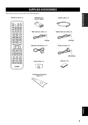
... cable (×1) STANDBY/ON POWER POWER AV TV DVD AUX VCR INPUT1 STB TV INPUT2 TV MACRO YSP 5BEAM 1 INPUTMODE SLEEP ST+3BEAM 2 3BEAM 3 STEREO TARGET 4 5 6 MUSIC 7 MOVIE 8 VOL MODE 9 SPORTS 0 OFF +10 SURROUND CH LEVEL CINEMA DSP MENU TEST ENTER RETURN VOLUME CH TV VOL OSD video pin cable (×1) Digital audio pin cable (×...
... cable (×1) STANDBY/ON POWER POWER AV TV DVD AUX VCR INPUT1 STB TV INPUT2 TV MACRO YSP 5BEAM 1 INPUTMODE SLEEP ST+3BEAM 2 3BEAM 3 STEREO TARGET 4 5 6 MUSIC 7 MOVIE 8 VOL MODE 9 SPORTS 0 OFF +10 SURROUND CH LEVEL CINEMA DSP MENU TEST ENTER RETURN VOLUME CH TV VOL OSD video pin cable (×1) Digital audio pin cable (×...

Owner's Manual
Page 10
...to run AUTO SETUP (see page 27). 2 Front panel display Shows information about the operational status of this unit consumes a small amount of power in order to receive infrared-signals from the remote control. 4 INPUT Press repeatedly to switch between input sources (TV, VCR, DVD or AUX)....5 VOLUME -/+ Controls the volume level of all audio channels (see page 38). 6 STANDBY/ON Turns on the power of this unit, you turn on the power of this unit or sets it can reproduce sound. • In the standby mode, this unit. 3 Remote control sensor Receives infrared signals from the remote control...
...to run AUTO SETUP (see page 27). 2 Front panel display Shows information about the operational status of this unit consumes a small amount of power in order to receive infrared-signals from the remote control. 4 INPUT Press repeatedly to switch between input sources (TV, VCR, DVD or AUX)....5 VOLUME -/+ Controls the volume level of all audio channels (see page 38). 6 STANDBY/ON Turns on the power of this unit, you turn on the power of this unit or sets it can reproduce sound. • In the standby mode, this unit. 3 Remote control sensor Receives infrared signals from the remote control...

Owner's Manual
Page 12
... to display the OSD of this unit (see page 20). 9 AC power supply cable Use to connect to connect a DVD player via a coaxial digital connection (see page 21). 8 CONTROLS AND FUNCTIONS Rear panel 1 23 4 9 5 6 (U.S.A. and Canada models only) Use to connect a YAMAHA subwoofer equipped with a SYSTEM CONNECTOR jack to this unit (see page...
... to display the OSD of this unit (see page 20). 9 AC power supply cable Use to connect to connect a DVD player via a coaxial digital connection (see page 21). 8 CONTROLS AND FUNCTIONS Rear panel 1 23 4 9 5 6 (U.S.A. and Canada models only) Use to connect a YAMAHA subwoofer equipped with a SYSTEM CONNECTOR jack to this unit (see page...

Owner's Manual
Page 13
...YSP Switches to the operation mode of this unit. 7 Numeric buttons Use to enter numbers. 8 Sound field program buttons Use to select sound field programs (see page 49). 9 CH LEVEL Adjusts the volume level of each channel (see page 79). 0 Cursor buttons / / / , ENTER Use to the standby mode (see page 83). G AV POWER... Turns on the power of the selected component or sets it to select and adjust SET MENU items. A TEST Outputs a test tone when adjusting the output level of each speaker (see page 78). H INPUT1/INPUT2 Selects the input source ...
...YSP Switches to the operation mode of this unit. 7 Numeric buttons Use to enter numbers. 8 Sound field program buttons Use to select sound field programs (see page 49). 9 CH LEVEL Adjusts the volume level of each channel (see page 79). 0 Cursor buttons / / / , ENTER Use to the standby mode (see page 83). G AV POWER... Turns on the power of the selected component or sets it to select and adjust SET MENU items. A TEST Outputs a test tone when adjusting the output level of each speaker (see page 78). H INPUT1/INPUT2 Selects the input source ...

Owner's Manual
Page 17
... Fasteners Peel off the film from each of the four supplied fasteners and then secure them to a dirty or wet surface will weaken the sticking power of the rack, etc. This unit may fall over and cause injury. • Make sure you wipe the surface of the tape, and this unit...
... Fasteners Peel off the film from each of the four supplied fasteners and then secure them to a dirty or wet surface will weaken the sticking power of the rack, etc. This unit may fall over and cause injury. • Make sure you wipe the surface of the tape, and this unit...

Owner's Manual
Page 18
Further, by connecting a subwoofer to the main power until all connections between components are complete. Audio connection Video connection TV This unit DVD player 14 Subwoofer VCR Digital satellite tuner, cable TV tuner or game console CAUTION Do not connect this unit or other components to ... for connecting external components such as your TV, DVD player, VCR, digital satellite tuner, cable TV tuner and game console. CONNECTIONS CONNECTIONS This unit is equipped with two optical digital jacks, one coaxial digital jack and two types of external components to this unit, you can...
Further, by connecting a subwoofer to the main power until all connections between components are complete. Audio connection Video connection TV This unit DVD player 14 Subwoofer VCR Digital satellite tuner, cable TV tuner or game console CAUTION Do not connect this unit or other components to ... for connecting external components such as your TV, DVD player, VCR, digital satellite tuner, cable TV tuner and game console. CONNECTIONS CONNECTIONS This unit is equipped with two optical digital jacks, one coaxial digital jack and two types of external components to this unit, you can...

Owner's Manual
Page 24
... monaural audio output jack (SUBWOOFER OUT) on the power of your subwoofer and then run AUTO SETUP (see page 26) or select SWFR for connections Subwoofer pin cable TV/STB AUX OPTICAL DVD COAXIAL DIGITAL INPUT SYSTEM CONNECTOR System connector cable (supplied with the YAMAHA subwoofer with a SYSTEM CONNECTOR jack, connect it to...
... monaural audio output jack (SUBWOOFER OUT) on the power of your subwoofer and then run AUTO SETUP (see page 26) or select SWFR for connections Subwoofer pin cable TV/STB AUX OPTICAL DVD COAXIAL DIGITAL INPUT SYSTEM CONNECTOR System connector cable (supplied with the YAMAHA subwoofer with a SYSTEM CONNECTOR jack, connect it to...

Owner's Manual
Page 25
Connecting the power supply cable Once all other connections are complete, plug the power supply cable into the AC wall outlet. CONNECTIONS To the AC outlet PREPARATION English 21
Connecting the power supply cable Once all other connections are complete, plug the power supply cable into the AC wall outlet. CONNECTIONS To the AC outlet PREPARATION English 21

Owner's Manual
Page 27
...an input source and switch to turn on the specific functions of the available remote control buttons for further information on the power of this unit. Note that the buttons on the remote control numbered 3 to 9 have different functions depending on the ... OFF +10 SURROUND TV CH LEVEL CINEMA DSP MENU 5 TEST ENTER RETURN 6 7 8 9 1 Input selector buttons 2 YSP 3 Beam mode buttons 4 Sound field program buttons 5 Cursor buttons / / / , ENTER 6 VOL MODE 7 SURROUND 8 MENU 9 RETURN Turning on the power VOLUME + STANDBY/ON STANDBY/ON POWER POWER AV TV DVD AUX VCR ...
...an input source and switch to turn on the specific functions of the available remote control buttons for further information on the power of this unit. Note that the buttons on the remote control numbered 3 to 9 have different functions depending on the ... OFF +10 SURROUND TV CH LEVEL CINEMA DSP MENU 5 TEST ENTER RETURN 6 7 8 9 1 Input selector buttons 2 YSP 3 Beam mode buttons 4 Sound field program buttons 5 Cursor buttons / / / , ENTER 6 VOL MODE 7 SURROUND 8 MENU 9 RETURN Turning on the power VOLUME + STANDBY/ON STANDBY/ON POWER POWER AV TV DVD AUX VCR ...
Owner's Manual
Page 28
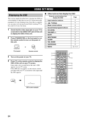
... to turn on the power of this unit's OSD appears on your TV is complete, you can enjoy real surround sound while watching TV in ... 1 Check that display the OSD Page 1 Input selector buttons 37 2 TruBass 3 Beam mode buttons 4 Sound field program buttons 5 CH LEVEL 6 VOLUME +/- 7 MUTE 8 INPUTMODE 9 SLEEP 0 VOL MODE A SURROUND B MENU 54 40 ...TV INPUT2 TV MACRO YSP 5BEAM 1 INPUTMODE SLEEP ST+3BEAM 2 3BEAM 3 STEREO TARGET 4 5 6 MUSIC 7 MOVIE 8 VOL MODE 9 SPORTS 0 OFF +10 SURROUND TV CH LEVEL CINEMA DSP MENU TEST ENTER RETURN VOLUME CH TV VOL MUTE TV...
... to turn on the power of this unit's OSD appears on your TV is complete, you can enjoy real surround sound while watching TV in ... 1 Check that display the OSD Page 1 Input selector buttons 37 2 TruBass 3 Beam mode buttons 4 Sound field program buttons 5 CH LEVEL 6 VOLUME +/- 7 MUTE 8 INPUTMODE 9 SLEEP 0 VOL MODE A SURROUND B MENU 54 40 ...TV INPUT2 TV MACRO YSP 5BEAM 1 INPUTMODE SLEEP ST+3BEAM 2 3BEAM 3 STEREO TARGET 4 5 6 MUSIC 7 MOVIE 8 VOL MODE 9 SPORTS 0 OFF +10 SURROUND TV CH LEVEL CINEMA DSP MENU TEST ENTER RETURN VOLUME CH TV VOL MUTE TV...

Owner's Manual
Page 32
TEST ENTER RETURN 28 VOLUME + STANDBY/ON 1 2 STANDBY/ON POWER POWER AV TV 3 4 DVD VCR STB TV AUX INPUT1 INPUT2 MACRO YSP ( ) INPUTMODE SLEEP 5BEAM 1 ST+3BEAM 2 3BEAM 3 STEREO UNIVERSAL 4 5 6 MUSIC 7 MOVIE 8 NIGHT 9 SPORTS 0 OFF +10 SURROUND CH LEVEL CINEMA DSP MENU 1 Disassemble the three parts of the circular-shaped part. AUTO SETUP Example of...
TEST ENTER RETURN 28 VOLUME + STANDBY/ON 1 2 STANDBY/ON POWER POWER AV TV 3 4 DVD VCR STB TV AUX INPUT1 INPUT2 MACRO YSP ( ) INPUTMODE SLEEP 5BEAM 1 ST+3BEAM 2 3BEAM 3 STEREO UNIVERSAL 4 5 6 MUSIC 7 MOVIE 8 NIGHT 9 SPORTS 0 OFF +10 SURROUND CH LEVEL CINEMA DSP MENU 1 Disassemble the three parts of the circular-shaped part. AUTO SETUP Example of...

Owner's Manual
Page 33
... on page 33 for appropriate remedies. STANDBY/ON Front panel or Remote control ENTER ENTER 2 Press YSP on the remote control to switch to select AUTO SETUP and then press ENTER. BEAM+SOUND OPTIMZ BEAM OPTIMZ only SOUND OPTIMZ only [ ]/[ ]:Up/Down [ENTER]:Enter English p 29 SETUP p AUTO SETUP Notes &#...conditions of your listening environment (see page 35). 1 Press STANDBY/ON on the front panel or on the remote control to turn on the power of the screen. • To return to manually adjust the corresponding parameters. • If the AUTO SETUP procedure stops and an error ...
... on page 33 for appropriate remedies. STANDBY/ON Front panel or Remote control ENTER ENTER 2 Press YSP on the remote control to switch to select AUTO SETUP and then press ENTER. BEAM+SOUND OPTIMZ BEAM OPTIMZ only SOUND OPTIMZ only [ ]/[ ]:Up/Down [ENTER]:Enter English p 29 SETUP p AUTO SETUP Notes &#...conditions of your listening environment (see page 35). 1 Press STANDBY/ON on the front panel or on the remote control to turn on the power of the screen. • To return to manually adjust the corresponding parameters. • If the AUTO SETUP procedure stops and an error ...

Owner's Manual
Page 41
DVD BASIC OPERATION INPUT VOLUME + STANDBY/ON VOL STANDBY/ON POWER POWER AV TV DVD AUX VCR INPUT1 STB TV INPUT2 TV MACRO Press VCR on the remote control to play back a satellite broadcast. AUX TV VOL ... (TV, STB, VCR, DVD or AUX) on the remote control to play back a TV program. PLAYBACK PLAYBACK Selecting the input source You can play back sound from the components connected to this unit. The name of the selected input source and the type of the selected input source input mode 37...
DVD BASIC OPERATION INPUT VOLUME + STANDBY/ON VOL STANDBY/ON POWER POWER AV TV DVD AUX VCR INPUT1 STB TV INPUT2 TV MACRO Press VCR on the remote control to play back a satellite broadcast. AUX TV VOL ... (TV, STB, VCR, DVD or AUX) on the remote control to play back a TV program. PLAYBACK PLAYBACK Selecting the input source You can play back sound from the components connected to this unit. The name of the selected input source and the type of the selected input source input mode 37...

Owner's Manual
Page 42
... the DVD player you are output from the speakers of the volume level appears in the front panel display. DVD Adjusting the volume INPUT VOLUME + STANDBY/ON VOLUME CH TV VOL MUTE TV INPUT TV MUTE Press VOLUME... refer to the owner's manual supplied with the TV and the DVD player. 1 Turn on the power of your DVD player using the remote control supplied with the DVD player. 2 Switch to the video ...unit to set the appropriate remote control codes for your TV and DVD player, you cannot hear any sound. 4 Press DVD on your TV using the remote control supplied with the TV so that the DVD...
... the DVD player you are output from the speakers of the volume level appears in the front panel display. DVD Adjusting the volume INPUT VOLUME + STANDBY/ON VOLUME CH TV VOL MUTE TV INPUT TV MUTE Press VOLUME... refer to the owner's manual supplied with the TV and the DVD player. 1 Turn on the power of your DVD player using the remote control supplied with the DVD player. 2 Switch to the video ...unit to set the appropriate remote control codes for your TV and DVD player, you cannot hear any sound. 4 Press DVD on your TV using the remote control supplied with the TV so that the DVD...


